Planning method for vehicle dynamic lane changing track based on 5G network
Technical Field
The invention relates to the field of automobiles, in particular to a planning method for a vehicle dynamic lane change track based on a 5G network.
Background
The reliability, safety and efficiency of the lane changing behavior of the vehicle are closely related to the driving safety of the vehicle and the smooth road. Therefore, research on lane changing behavior of intelligent vehicles has been one of the keys of automatic driving.
The automatic driving automobile needs to have the capability of predicting the motion track of surrounding vehicles, so that reference is provided for behavior decision and track planning of the unmanned automobile, and the safety and comfort of the unmanned automobile are fully ensured. Currently, studies on lane change trajectory planning generally have insufficient real-time performance and safety consideration for lane change. The method is mainly characterized in that: firstly, the planning scene of the track changing track in the existing research is simple, and it is mostly assumed that the speed of vehicles around the track changing vehicle is kept unchanged and the number of vehicles around the track changing vehicle is small in the track changing process; secondly, the planning of the lane changing track is mostly finished before the lane changing is started, and the real-time change of the motion state of surrounding vehicles in the lane changing process is not considered enough, so that the lane changing operation according to the planned track before the lane changing has potential collision danger; thirdly, the influence of the future motion trail of the surrounding vehicle on the lane changing vehicle trail planning is not considered, so that the planned trail is not suitable for the change of the future motion trail of the surrounding vehicle, and the lane changing safety is threatened.
Disclosure of Invention
The invention aims to provide a vehicle dynamic lane change track planning method based on a 5G network aiming at the corresponding defects of the prior art, which utilizes the large bandwidth, low time delay and a vehicle-to-vehicle communication system (V2V) of the 5G network to accurately acquire the state information of vehicles around a lane change vehicle in real time, establishes a GRU (gate Recurrent Unit) network model to predict the motion track of the vehicles around, calculates the optimal dynamic lane change track of the lane change vehicle through three indexes of lane change safety, lane change efficiency and lane change comfort, realizes the dynamic lane change track planning of the lane change vehicle in a complex and changeable real traffic scene, and improves the real-time performance, safety and reliability of the lane change planning of the lane change vehicle.
The purpose of the invention is realized by adopting the following scheme: a planning method for a vehicle dynamic lane change track based on a 5G network comprises the following steps:
1) performing a lane change test in an actual road environment by an excellent driver, acquiring the driving track data of vehicles around a lane change vehicle by using a 5G network through a global positioning system and a vehicle-to-vehicle communication system (V2V), and performing coordinate unification on the track coordinates of the lane change vehicle and the surrounding vehicles to obtain continuous driving track points of the surrounding vehicles as an original data set;
2) in the data of the original data set obtained in the step 1), taking data of n time periods (t-n +1, t-n +2, …, t) before the time t as the input of a GRU network model, and taking the data at the time t +1 as the output of the GRU network model to construct a plurality of GRU network models to form a GRU network structure diagram for predicting the driving track of surrounding vehicles;
3) dividing the original data set obtained in the step 1) into a training set and a testing set;
3-1) training each GRU network model in the GRU network structure diagram obtained in the step 2) through data of a training set, determining weight parameters and bias vectors of each GRU network model, and obtaining a trajectory prediction model based on the GRU network model;
3-2) carrying out reliability verification test on the prediction result of the trajectory prediction model based on the GRU network model obtained in the step 3-1) by using the data of the test set;
4) taking the GRU network model-based track prediction model passing the reliability verification test of the prediction result in the step 3-1) as a constraint condition for the lane change decision and track planning of the lane change vehicle, and establishing a lane change scene model;
5) constructing a dynamic lane change track planning model of the lane change vehicle by using a cost function meeting constraint conditions in the lane change scene model established in the step 4), and calculating a lane change planning track of the lane change vehicle;
6) dividing the time of the lane changing planning track of the lane changing vehicle into a plurality of time steps, collecting the running track data of surrounding vehicles by the lane changing vehicle in each time step according to the real-time traffic flow condition, repeating the steps 2) to 5) to perform rolling calculation to obtain the real-time lane changing planning track in each time step, and combining the real-time lane changing planning tracks of all the time steps to obtain the dynamic lane changing track of the lane changing vehicle responding to the change of the surrounding traffic flow in real time.
The driving track data in the step 1) is the state information of the vehicle at the time t, including position information and speed information, namely (x)t,yt,vt)。
The GRU network model in the step 2) is represented by the following formula:
zt=sigmoid(Wz·[ht-1,xt])
rt=sigmoid(Wr·[ht-1,xt])
in the formula, r
tReset gate, z, representing a GRU network model
tUpdate door, x, representing a GRU network model
tAn input representing a current node is shown,
candidate hidden state, h, representing current node output
tRepresenting the hidden state of the current node output.
The steps of determining the weight parameters and the offset vectors of the GRU network models in the step 3-1) are as follows:
firstly, initializing weight parameters and offset vectors of a GRU network, sending data of a training set obtained in the step 3) into a GRU network model by using an initial learning rate for training, taking data of n time periods before t time as sample data, taking data of t +1 time as label data, minimizing a loss function of the GRU network model by adopting a Gradient Descent method (Gradient decision Optimization), and finishing training of the GRU network model after multiple iterations to obtain the weight parameters and the offset vectors of the GRU network model.
The cost function satisfying the constraint condition in step 5) is as follows:
cost=f(xf,j)
in the formula, xfThe longitudinal distance for the vehicle to minimize lane changes, j is the change in vehicle acceleration.
X in the cost functionfThe following formula is satisfied as a constraint:
in the formula (I), the compound is shown in the specification,
yffor changing the longitudinal distance, u is the vehicle speed, arlmaxThe maximum lateral acceleration of the lane change vehicle rollover.
The method for calculating the lane changing track of the lane changing vehicle in the step 5) adopts an interior point method.
The invention carries out lane change test in the actual road environment by excellent drivers (namely drivers with C1 driving license for more than 3 years and without traffic violation and accidents), and utilizes the characteristics of large bandwidth and low time delay of a 5G network to enable a vehicle-to-vehicle communication system (V2V) to accurately acquire the state information of vehicles around the lane change vehicle in real time by a global positioning system, namely the lane change vehicle acquires the motion track and the state information of the surrounding traffic flow in real time, coordinates unify the track coordinates of the lane change vehicle and the surrounding vehicles to obtain continuous running track points of the surrounding vehicles as an original data set, and constructs a plurality of GRU network models by utilizing the data of the original data set to form a GRU network structure chart for predicting the running track of the surrounding vehicles.
The GRU Network model is one of Recurrent Neural Networks (RNNs), solves the problems of gradient and the like in long-term memory and back propagation, has low requirements on computer memory and is easier to train, so the GRU Network model is constructed, the problem of gradient disappearance of a standard RNN is solved, the tracks of surrounding vehicles are predicted on the basis of ensuring fast learning, safe and reliable guarantee is provided for the track changing track planning of a vehicle with a changed track, and the danger of the vehicle with the changed track in the track changing process is avoided to the greatest extent.
The GRU network model predicts the running track of the surrounding vehicle at the time t +1 according to the running track data (global coordinates and speed) of the surrounding vehicle at n time periods (t-n +1, t-n +2, …, t) before the time t in the original data set, wherein the running track data in the step 1) is the state information of the vehicle at the time t, and comprises position information and speed information, namely (x)t,yt,vt) The method and the device reflect the actual situation of the traffic flow around the lane changing vehicle to the maximum extent and provide accurate data support for building a GRU network model.
Since the lane change process involves at least two adjacent lanes, the traffic efficiency of the road is affected during the lane change process, and the longitudinal distance x of the lane change is minimizedfThe influence on traffic efficiency caused by lane changing can be reduced, so the longitudinal distance x for minimizing the lane changing of the vehicle is selectedfTo describe lane change efficiency; since the change of speed and acceleration during lane changing can bring comfort influence, generally speaking, passengers can not feel when the vehicle runs at a constant speed, the passengers can adapt by adjusting themselves when the vehicle runs at a constant acceleration, and the passengers can lose the balance of adjustment when the acceleration of the vehicle changes, so that the passengers feel uncomfortable, and therefore the change value j of the acceleration of the vehicle is selected as a parameter for measuring the comfort of the passengers.
Therefore, the cost function satisfying the constraint condition in step 5) is as follows:
cost=f(xf,j)
in the formula, xfThe longitudinal distance for the vehicle to minimize lane changes, j is the change in vehicle acceleration.
X in the cost functionfThe following formula is satisfied as a constraint:
in the formula (I), the compound is shown in the specification,
yffor changing the longitudinal distance, u is the vehicle speed, arlmaxThe maximum lateral acceleration of the lane change vehicle rollover.
The interior point method in the step 5) is an algorithm for solving a linear programming or nonlinear convex optimization problem.
The GRU network model, the track prediction model, the lane change scene model and the dynamic lane change track planning model of the lane change vehicle are all established in a computer.
Drawings
Fig. 1 is a diagram of a GRU network architecture for predicting the travel trajectory of surrounding vehicles;
FIG. 2 is a block diagram of a GRU network model;
FIG. 3 is a schematic view of a lane-change scene;
FIG. 4 is a dynamic lane change trajectory chart of the lane change vehicle;
FIG. 5 is a schematic view of a lane-change model;
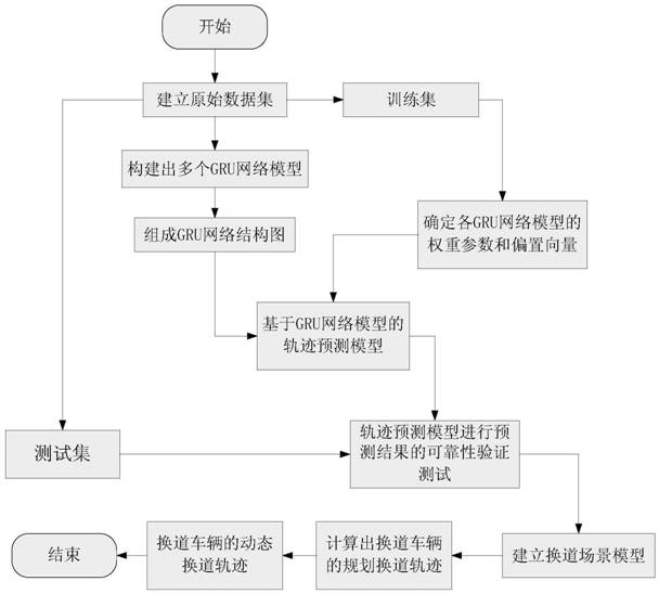
FIG. 6 is a flow chart of the present invention;
FIG. 7 is a real-time lane change planning trajectory diagram of the lane change vehicle within the 1 st time step;
FIG. 8 is a real-time lane change planning trajectory diagram of the lane change vehicle within the 2 nd time step;
FIG. 9 is a real-time lane change planning trajectory diagram of the lane change vehicle within the 3 rd time step;
FIG. 10 is a real-time lane change planning trajectory diagram of the lane change vehicle within the 4 th time step;
FIG. 11 is a real-time lane change planning trajectory diagram of the lane change vehicle within the 5 th time step;
FIG. 12 is a combined diagram of real-time lane change planning trajectories for each time step of the lane change vehicles;
FIG. 13 is a dynamic lane change trajectory diagram for a lane change vehicle responding in real time to changes in ambient traffic flow.
Detailed Description
As shown in fig. 1 to 13, a method for planning a vehicle dynamic lane change track based on a 5G network includes the following steps:
1) performing a lane change test in an actual road environment by an excellent driver, acquiring the driving track data of vehicles around a lane change vehicle by using a 5G network through a global positioning system and a vehicle-to-vehicle communication system (V2V), and performing coordinate unification on the track coordinates of the lane change vehicle and the surrounding vehicles to obtain continuous driving track points of the surrounding vehicles as an original data set;
the driving track data in the step 1) is the state information of the vehicle at the time t, including position information and speed information, namely (x)t,yt,vt)。
For example, 6 excellent drivers for male and female are selected to perform lane change test in real road environment, and the lane change operation is performed under the lane change scene as shown in FIG. 3 by using the vehicle speeds of 20km/h,40km/h and 60km/h, collecting the running track data of vehicles around the lane-changing vehicle by a Differential Global Positioning System (DGPS or Differential GPS for short), selecting a Global coordinate origin, coordinate unification is carried out on track coordinates of surrounding vehicles, running track points of n time periods before t time of the surrounding vehicles driven by 6 excellent drivers are collected to serve as original data, the collected original data are usually provided with a lot of noise points and are unstable and obviously fluctuated in many times, the collected original data need to be subjected to noise reduction treatment, abnormal data are removed, and then the original data set is formed in a summarizing mode.
2) In the data of the original data set obtained in the step 1), taking data of n time periods (t-n +1, t-n +2, …, t) before the time t as the input of a GRU network model, and taking the data at the time t +1 as the output of the GRU network model to construct a plurality of GRU network models to form a GRU network structure diagram for predicting the driving track of surrounding vehicles;
the GRU network model in the step 2) is represented by the following formula:
zt=sigmoid(Wz·[ht-1,xt])
rt=sigmoid(Wr·[ht-1,xt])
in the formula, r
tReset gate, z, representing a GRU network model
tUpdate door, x, representing a GRU network model
tAn input representing a current node is shown,
candidate hidden state, h, representing current node output
tRepresenting the hidden state of the current node output.
As shown in fig. 1, the structure diagram of the GRU network for predicting the driving trajectory of the surrounding vehicle is composed of a plurality of GRU network models, the driving trajectory at the next time is predicted according to the driving trajectory n time periods before a certain time, and compared with other RNN network models (such as LSTM), the GRU network model has the most advantage that the same update gate control z is usedtThe selective forgetting and memorizing can be carried out, so that the forgetting and the selected information can be linked, namely selective forgetting can be carried out on the dimension information transmitted in, and the forgetting weight can be compensated by using the corresponding weight containing the current input, so that the constant state can be kept.
3) The raw data set obtained in step 1) is divided into a training set and a test set, for example, 80% as the training set and 20% as the test set.
3-1) training each GRU network model in the GRU network structure diagram obtained in the step 2) through data of a training set, determining weight parameters and bias vectors of each GRU network model, and obtaining a trajectory prediction model based on the GRU network model;
the steps of determining the weight parameters and the offset vectors of the GRU network models in the step 3-1) are as follows:
firstly, initializing weight parameters and offset vectors of a GRU network, sending data of a training set obtained in the step 3) into a GRU network model by using an initial learning rate for training, taking data of n time periods before t time as sample data, taking data of t +1 time as label data, minimizing a loss function of the GRU network model by adopting a Gradient Descent method (Gradient decision Optimization), and finishing training of the GRU network model after multiple iterations to obtain the weight parameters and the offset vectors of the GRU network model.
3-2) carrying out reliability verification test on the prediction result of the trajectory prediction model based on the GRU network model obtained in the step 3-1) by using the data of the test set;
4) taking the GRU network model-based track prediction model passing the reliability verification test of the prediction result in the step 3-1) as a constraint condition for the lane change decision and track planning of the lane change vehicle, and establishing a lane change scene model;
as shown in fig. 3, in the present embodiment, the lane change scene is a three-lane scene, and the front and rear six vehicles do not exceed the maximum speed limit of the vehicle, and the left lane is a fast lane; supposing that in the lane changing process, the vehicle behind the current lane completely notices the lane changing operation of the lane changing vehicle and adjusts the speed of the vehicle by matching with the lane changing vehicle;
wherein, the lane changing vehicle is also called as a self vehicle and is denoted by E; peripheral vehicles (front left, front right, rear left, rear right) are denoted by FL, FM, FR, RL, RM, RR, respectively;
5) constructing a dynamic lane change track planning model of the lane change vehicle by using a cost function meeting constraint conditions in the lane change scene model established in the step 4), and calculating a lane change planning track of the lane change vehicle;
the cost function satisfying the constraint condition in step 5) is as follows:
cost=f(xf,j)
in the formula, xfThe longitudinal distance for the vehicle to minimize lane changes, j is the change in vehicle acceleration.
X in the cost functionfThe following formula is satisfied as a constraint:
in the formula (I), the compound is shown in the specification,
yffor changing the longitudinal distance, u is the vehicle speed, arlmaxThe maximum lateral acceleration of the lane change vehicle rollover.
The method for calculating the lane changing track of the lane changing vehicle in the step 5) adopts an interior point method.
6) Dividing the time of the lane change planned track of the lane change vehicle into a plurality of time steps, in the embodiment, dividing the time of the lane change planned track of the lane change vehicle into five time steps, collecting the running track data of surrounding vehicles by the lane change vehicle in each time step according to the real-time traffic flow condition, repeating the steps 2) to 5) for rolling calculation to obtain the real-time lane change planned track in each time step, and combining the real-time lane change planned tracks of the time steps to obtain the dynamic lane change track of the lane change vehicle responding to the change of the surrounding traffic flow in real time, as shown in fig. 7 to 13.
The above description is only a preferred embodiment of the present invention, and is not intended to limit the present invention, and those skilled in the art can make modifications without departing from the spirit of the present invention.