CN1111443A - Device for suspending a longitudinally extended object - Google Patents
Device for suspending a longitudinally extended object Download PDFInfo
- Publication number
- CN1111443A CN1111443A CN94190434.2A CN94190434A CN1111443A CN 1111443 A CN1111443 A CN 1111443A CN 94190434 A CN94190434 A CN 94190434A CN 1111443 A CN1111443 A CN 1111443A
- Authority
- CN
- China
- Prior art keywords
- clamping
- anchor clamps
- another
- clamping component
- section
- Prior art date
- Legal status (The legal status is an assumption and is not a legal conclusion. Google has not performed a legal analysis and makes no representation as to the accuracy of the status listed.)
- Pending
Links
Images


Classifications
-
- A—HUMAN NECESSITIES
- A47—FURNITURE; DOMESTIC ARTICLES OR APPLIANCES; COFFEE MILLS; SPICE MILLS; SUCTION CLEANERS IN GENERAL
- A47L—DOMESTIC WASHING OR CLEANING; SUCTION CLEANERS IN GENERAL
- A47L13/00—Implements for cleaning floors, carpets, furniture, walls, or wall coverings
- A47L13/10—Scrubbing; Scouring; Cleaning; Polishing
- A47L13/50—Auxiliary implements
- A47L13/51—Storing of cleaning tools, e.g. containers therefor
- A47L13/512—Clamping devices for hanging the tools
Landscapes
- Supports Or Holders For Household Use (AREA)
- Load-Engaging Elements For Cranes (AREA)
- Clamps And Clips (AREA)
- Supports For Pipes And Cables (AREA)
- Carriages For Children, Sleds, And Other Hand-Operated Vehicles (AREA)
- Vehicle Body Suspensions (AREA)
- Advancing Webs (AREA)
- Forklifts And Lifting Vehicles (AREA)
- Holders For Apparel And Elements Relating To Apparel (AREA)
- Sheet Holders (AREA)
Abstract
The invention provides a device for suspending especially a substantially longitudinally extended object comprising at least one clamping component (1) which can be directionally moved against a wall or another clamping component (1) in order to hold the object firmly between them through its own weight. At least one component has at least two vertically spaced supporting sections (3, 5) and/or at least one flat supporting region which can engage in one side of the object when it is clamped or suspended and force the object against the wall or the other component.
Description
The present invention relates to a kind of device of longitudinally extending object basically that regularly hangs particularly, this device comprises at least one clamping component, this clamping component can be towards a wall or the motion of another clamping component, so that by the deadweight of object object be held in clamping component and wall or and another clamping component between, the invention still further relates to a kind of equipment, this equipment comprise at least one regularly hang have different-thickness or width, the device of longitudinally extending object basically.
In order regularly to hang instrument, home appliances, gardening and hobby utensil, skis, sled and similar object, known a lot of device of promising number or the equipment of disclosing, European patent application EP-A-507 has for example described a kind of cramp frame in 721, and object can push in this cramp frame.But the shortcoming of this cramp frame is, can only on this bow folder, insert and put object such as band bar with specific dimensions, band or have necessarily the object of shank diameter.
At United States Patent (USP) 4,170, propose to be used for regularly hanging the clamping component of work implement in 333 and European patent EP-PS180,884, these two kinds of clamping components are all according to the diminishing principle in horizontal cross-section.In these two kinds of utensils, object is pushed in the toxoplasm, when pushing object, the horizontal cross-section is bigger.By decontroling the utensil that will hang, cramp frame is also to lower swing.In view of the above, thus the horizontal cross-section dwindles to some extent and clamps utensil.Its shortcoming is that also these cramp frames can only be used for the utensil that clamping has a certain size or a uniform section, and the handle of a circle is preferably arranged on the utensil.Another shortcoming of these cramp frames is that utensil is not a vertical hanging when letting go, but for example the bottom leans to wall in its rear.These cramp frames for example are unsuitable for hanging skis.
At United States Patent (USP) 4,852, a kind of clamping device has been described once more in 747, this device realizes that by the deadweight of an object one is moved clamping action between projection and the wall in tiltable.When letting go, the pinch roll handle that crimp lug or roller tilt to move downward for example skis is pressed on the wall.But its shortcoming is, when hanging the bigger object of weight, the clamping action of realizing by pinch roll down is too little, and the object between projection and the wall therefore can landing.
Recently, a kind of clamping device that is used to the instrument of hanging has been described in German prospectus DE-OS3818031, this device is when the instrument of relieving, be implemented in two clamping actions between the movable cylinder, these two cylinders are mutually pivotally connected together by two sector gears, and the shortcoming of this device is, under the situation that does not have accurately to aim at mutually at two pinch roll along continuous straight runs, the object meeting deflection that is held therebetween causes the superconducting tilting suspension state.In addition, go back the danger that existence can not get correct clamping and landing in this case.
Therefore, task of the present invention is, provides a kind of and regularly hangs to the object that stretches, and as the clamping device of instrument, garden tool set, snow slab and similar object, it can reliably, not hang object on the bias and simply this clamping device.
Invent another task and be, in such clamping device, can regularly hang different in width or thick object.
According to the present invention, the technical scheme of finishing the task of stating comprises at least one clamping component, this member can be towards a wall or the motion of another clamping element, so that the deadweight by described object is held in this object between clamping component and wall or another clamping component securely, at least one presss from both sides member, it comprises at least two supporting areas on spaced support section of vertical direction and/or the individual at least plane that is provided with, so that be bonded on the side of object, and shift onto object on the wall or shift onto on another clamping component in clamping or when hanging object.
In order to hang particularly a kind of longitudinally extending basically object, as an instrument, a garden tool set or home appliances, skis or a similar object, the present invention proposes a kind of device, this device has at least one clamping component, this clamping component can be towards an opposed wall or to another clamping component motion, so that the deadweight by object clamps betwixt, as an instrument or similar object.Here importantly: have a clamping component at least, this clamping component comprises at least two the vertically supporting section of space and/or the supporting areas at least one plane, so that be bonded on the side of object in clamping or when hanging object and shift onto object on the wall or shift onto on another clamping component.
According to a version of the present invention, at least one clamping component is to be arranged to can or can swing to another clamping component that is installed on plate-type component such as the base plate to a wall basically.
This clamping component is arranged to like this and can be swung, i.e. at least two portion's sections or a plane area, can be respectively around two axle center, be each section can be around an axle center or this plane area at least almost around at least two axis swings this is moved downward towards wall or towards the curve that the motion of another clamping component becomes the gripping object body in parallelogram ground.
Preferably having a clamping component at least is the shape of anchor clamps or jaw, wherein, two portion's sections that constitute these anchor clamps and establish or plane area be towards or line by these two portion's sections or its joint face, portion's section or plane area are arranged essentially parallel to gripping section or plane on wall or another clamping component.
Gripping section or plane area be one with plate-type component such as the vertical substantially extending longitudinally structure of base plate.
Another clamping component preferably has at least one some supporting, extending longitudinally supporting or a surface bearing, treats that the object of clamping is pushed against in the above-mentioned supporting by that relative clamping component.
According to a preferred construction form, one of them clamping component or anchor clamps are parallelogram sturcutre, and one of them limit and plate-type component are fixedly connected as base plate, and its that relative limit can be set as parallel with it towards wall or the swing of another clamping component, in order to the clamping object.
For carrying out this swing, or a relative limit is set as and can be located at shaft swings on one side around two, or anchor clamps at least a portion can be made by the material of flexibility or flexible or caoutchouc elasticity, so that relative limit can be swung aside.As both metallic plates of flexibility or elastomeric material, also polymeric material, as commercial habitual plasticising, softening with the plastics that plastified, or elastoplast or rubber.Generally be to make this class anchor clamps with polymeric material or elastoplast.Here importantly, in order to clamp the bigger object of weight, and don't anchor clamps are sustained damage, this polymer or plastics should have enough flexibilities, and keep its corresponding strength, such as thermoplastic polyester, polyamide, Polyurethane, polyvinyl chloride etc.
Certainly also can relative one side can be swung by structural measure, this structural measure be that for example on a limit, the wall thickness of its end region selects thinlyyer, so that make anchor clamps have certain flexibility in these districts.
According to another version and in order to increase the flexibility of anchor clamps, in the anchor clamps of parallelogram sturcutre, do not have can be free movable opposite side, so that form one have in the front side opening like the U-shaped anchor clamps, these anchor clamps have two that be in distal portion, be parallel to each other and almost stretch perpendicular to plate-type component such as base plate, rib shapes or stripes section.
These two like the rib shape portion section warpage that can make progress, so that become the Gu Xingbi of fixture type, these two walls are almost configuration up and down vertically under clamp position.In addition,, can set up a rubber covering layer in these rib shape portion sections in order to strengthen clamping action when the clamping object, or on this rib shape portion section one of plug-in mounting spherical columniform, that make by rubber or a kind of elastomeric material.
In order to improve the clamping effect, also can or cover thereon and add one deck and can increase the material for the treatment of the sliding friction in portion's section or face shape district of clamping object portion's section or plane area hacking.
According to another preferred constructive form of clamping device, another clamping component similar in appearance to a relative clamping component be set as plane symmetry almost and on its opposite, two clamping components then are set as and can swing in opposite directions.Between above-mentioned two clamping components is by treating the object of clamping, constituting as a pair of skis like the plane of symmetry.By the above-mentioned plane symmetry structure of two clamping components, the object for the treatment of clamping just is clamped in respectively between the plane of two be mutually symmetrical portion's section of being provided with or two symmetrical structures.When clamping, earlier the placement object, be inserted into from bottom to top between two clamping components as a garden tool set or a pair of skis, in view of the above, two clamping components are pushed open dorsad.Decontrol object then, in view of the above, two clamping components under the deadweight effect of object, are subjected to promoting in opposite directions thereby clamping object as two anchor clamps.Face the gripping section on ground mutually or have a flat grip district respectively because two clamping components have two respectively, occur deflection when decontroling so can prevent object to be placed.In addition, because contact-making surface is bigger, so also guarantee to clamp reliably the bigger object of weight.
In order to guarantee also to hang the bigger object of weight with clamping device of the present invention, as iron staff and similar object, for example also can set up a plurality of clamping components separately in vertical direction towards a wall or towards other clamping component of special similar amt, so as between these clamping components this object of clamping.
Clamping device of the present invention comprises that also at least one clamping component is can or can swingingly be provided with towards another clamping component that is contained on the flat component towards wall basically.Clamping component is set as and can swings, each that makes at least two portion's sections or plane area can be respectively around two axle center, be each section can be around a specific axle center or face with two axis swings of mode of parallelogram, make this become moving downward of a curve towards wall or towards the motion of the clamping object of another clamping component; At least one clamping component is anchor clamps, wherein, constitutes portion's section of these anchor clamps or its linkage section and/or plane area and is and be arranged to be arranged essentially parallel to wall or the portion's section or the plane that are used to clamp on another clamping component relatively.One of portion's section or plane is the extending longitudinally structure vertical substantially with plate-type component; Another clamping component has at least one supporting as a supporting, extending longitudinally supporting or a flat bearing, treats that the object of clamping is shifted onto in this supporting by that clamping component on opposite.One of them clamping component is arranged to the parallelogram anchor clamps, one of them limit and plate-type component are permanently connected, and that limit of its opposite face can be set as, and side direction is parallel with it moves and swings or swing to another clamping component towards wall, with the clamping object, anchor clamps to small part is to be made by material flexibility or flexible, so that the relative edge can be swung to a side.In the anchor clamps of parallelogram sturcutre, do not have can be free movable the relative edge, so that form one have in the front side opening like the U-shaped anchor clamps, these anchor clamps have two be in distal portion, be parallel to each other and the perpendicular plate-type component stretches, rib shape or stripes section.Rib shape portion section is the warpage that makes progress, so that each forms the Gu Xingbi of fixture type, these two walls almost vertically dispose up and down under unclamped state.Have one like the anchor clamps of U-shaped and be positioned at fixed body dorsal part, that make by sturdy material, two U-shaped legs are fixed in this fixed body, two U-shaped legs that are parallel to each other are to be made by material flexibility or caoutchouc elasticity, so as to make two lay respectively at the leg end be preferably plane or stripes Duan Kexiang another or from another clamping component or to another or from another anchor clamps swing; Portion's section and/or plane area to small part is arranged to surperficial hacking, or covers the material that one deck reduces sliding friction thereon; Another clamping component and relative that clamping component be set as plane symmetry basically and be located at its opposite, two clamping components then are arranged to swing in opposite directions; Towards a wall or towards other clamping components of special similar amt, be provided with a plurality of clamping components in vertical direction.
The clamping component that the present invention proposes preferably is located on the base plate, and this base plate is the rail mounted structure and for example is provided with locking device along track.Clamping component is located on this track with longitudinal movement and lockably as anchor clamps.Because each clamping component can vertically move as anchor clamps, so can hang utensil, instrument or the exercise of different-thickness or width betwixt.For example,, move out corresponding spacing dorsad, on one " the skiing equipment hangs frame ", also can hang sled by anchor clamps with this clamping component that vertically moves.When hanging home appliances and garden tool set, determine it is favourable, can hang the utensil and the instrument of different-thickness or width with this clamping device.
According to another version, clamping component also can be located at for example on the guide plate, and these guide plates have clamping device or fixture, so that the guide plate that has clamping component is fixed on the rail mounted base plate.These clampings or fixture are to be arranged to make clamping component infinitely to move along track.
The present invention also provides such clamping device, and its at least one clamping component preferably can add can being fixed on another board-like or rail mounted member, so that the object of clamping different-thickness or width of infinitely vertically moving with unclamping again.Clamping component that at least one or two match or each of anchor clamps are located on the guide plate, guide plate has at least more than one side or clamps the clamping of vertical and its biasing or interval or the fixture of board-like or another member of rail mounted from the below, so that guide plate releasably is fixed on another member board-like or rail mounted again.Guide rail on guide section and another member is an oblique angle, promising guide rail on guide section and the gathering sill established, its size is to be provided with like this, guide plate released and the pendulum from and when guide section is substantially perpendicular to track, guide plate can move freely along another member, but clamping or fixture when guide plate being fixed on another member, track is almost to be clamped in the gathering sill at least; Clamp or fixture have an eccentric stiffener by this eccentric stiffener by rotate or clamp can make guide plate releasably be fixed on board-like again or another member of rail mounted on.The clamping component that this device uses this present invention to limit hang have different-thickness or different size, the optimum structure form of this equipment of extending longitudinally object basically.
Embodiment shown in reaching by accompanying drawing below describes structure of the present invention, characteristics and other purposes in detail.Wherein:
Fig. 1 is the preceding top view of a clamping device of the present invention, it comprise one can be towards the anchor clamps of wall swing;
Fig. 2 is the preceding top view of another version of anchor clamps of the present invention;
Fig. 3 is the front view of another clamping device, and it comprises two anchor clamps that can swing in opposite directions;
Fig. 4 is the front-side perspective view of another version of clamping device, and it comprises the fixture of two anchor clamps that can swing in opposite directions and other placement appurtenances;
Fig. 5 is an anchor clamps front-side perspective view shown in Figure 4, and wherein each anchor clamps is equiped with a cover layer that increases sliding friction;
Fig. 6 is a plurality of in the anchor clamps front-side perspective view that constitutes according to the present invention shown in Fig. 4 and Fig. 5;
Fig. 7 is the front-side perspective view according to another structure of clamping device of the present invention;
Fig. 8 is another front-side perspective view according to clamping device of the present invention, and it comprises two and is applicable to the anchor clamps that hang a pair of skis;
Fig. 9 is the front-side perspective view of clamping device shown in Figure 8, and this device is located on the rail mounted base plate that has a plurality of locking components;
Figure 10 for base plate shown in Figure 9 and two at the front perspective view of deviating from the anchor clamps under the state;
Figure 11 be the rail mounted base plate another version schematically before perspective view then, be applicable to similar Fig. 8 and clamping device shown in Figure 9 are set;
Figure 12 a and Figure 12 b are the schematic diagram of anchor clamps of clamping device shown in Figure 11, and these anchor clamps are in the state of vertically moving and stationary state respectively on the rail mounted base plate;
Figure 13 a and 13b are respectively the front view and the vertical view of another version of clamping device, are applicable to along the rail mounted base plate infinitely to vertically move;
Figure 14 a and Figure 14 b are respectively the front view and the vertical view of the guide plate of clamping device shown in Figure 13 a and Figure 13 b, and this guide plate is applicable to that the stepless of clamping device vertically moves;
Figure 15 a, Figure 15 b and Figure 15 c reach an object is subjected to clamping between clamping device schematic diagram on the rail mounted base plate for clamping device shown in Figure 13 a and the 13b is located at;
Figure 16 is subjected to the front view of clamping on a rail mounted base plate that comprises clamping device shown in a plurality of Figure 13 a and Figure 13 b for the object of different-thickness or different size; With
Figure 17 a and Figure 17 b are respectively the perspective view and the vertical view of another structure of guide plate or base plate, are applicable to that the stepless of clamping device vertically moves.
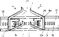
Fig. 1 expresses the schematically preceding top view according to a kind of clamping device of the present invention.This device includes anchor clamps 1 on the one hand, and include an opposed wall or bearing-surface 21 on the other hand, anchor clamps 1 can be towards these wall 21 swings, so that in anchor clamps 1 and wall 21 swings, (or elongation) object so that one of clamping is longitudinally extending in the space 23 between anchor clamps 1 and wall 21, as a broomstick, gardening hoe or a pair of skis.
The anchor clamps 1 that constitute according to the present invention comprise longitudinally extending the section 3 and 5 of two its fronts towards wall 21, and these two portion's sections are parallel to wall 21 and are provided with, and they are substantially perpendicular to base plate 17 extending longitudinallies that are installed in anchor clamps 1 back.These two portion's sections 3 and 5 for example interconnect by a connecting plate or a joint face 4.In addition, anchor clamps 1 also have a connecting plate 11 parallel with respect to connecting plate (or wallboard) 4, and this connecting plate (or wallboard) 11 is preferably fixedlyed connected with the base plate 17 that is in its back.In order to make anchor clamps 1 hypothesis have the seemingly shape of parallelogram, then on the side direction of connecting plate (or wallboard) 11, be provided with two hinge type jockeys 8 and 10 that are connected with 15 with other two side wall surfaces 13.By base plate 17, anchor clamps 1 but also wall 21 all can be fixedlyed connected with a wall that is positioned at its back.In order to clamp an object securely, at first just this object is moved from bottom to top and be inserted in the space 23 between anchor clamps 1 and the wall 21, in view of the above, anchor clamps 1 are upwards boosted.Decontrol the object treat clamping then, like this, object is because the friction that forms on the weight of himself and two portion's sections 3 and 5 and being pushed against on the wall 21 by anchor clamps 1, thereby obtains clamping.
According to the present invention, important point just is, anchor clamps 1 or portion's section 3 and 5 of two clamping objects of tool perhaps have a planar support surface, as wallboard 4 under the projection structure situation outside two portion's sections 3 and 5 are not.The object of guaranteeing to hang by these two portion's sections or this planar support surface can not tilt and can hang heavier object without a doubt, and object is slided between anchor clamps and wall.
Fig. 2 expresses the preceding top view of another version of the anchor clamps that constitute according to the present invention, in this version, two portion's sections 3 that are positioned at the front side with 5 or wallboard 4 be connected by a center hinge 4a, and be connected with a swinging axle 7 by a connecting plate or a wallboard 9.Object also is to be clamped between two portion's sections 3,5 or wallboard 4 and the relative wall 21.
Fig. 3 expresses the structure according to a preferred embodiment of clamping device of the present invention, wherein is provided with two opposed facing anchor clamps 1, and these two anchor clamps are arranged to plane symmetry with respect to " clamping face " of central stretching, extension.The member identical with Fig. 1 and Fig. 2 also indicates identical label simultaneously.Be with the difference of Fig. 1, squab panel 11 does not comprise and is located at each distolateral two hinges or turning cylinder, wallboard 11 then is to be formed by the crooked closure of flexible material in all cases, so that make two axle point 8a of relative wallboard and 10a that certain swing or rotation be arranged.Two anchor clamps 1 shown in Figure 3 generally can be all by flexibility or elastic plastic material, makes as iron sheet plate or flexibility or elasticity, and in view of the above, these two anchor clamps just have certain swing automatically at axle point 8a and 10a place.Obviously, the selection by flexibility or elastomeric material can also make two anchor clamps 1 song of tilting upward slightly along two opposed facing sides 13 and 15.In order to hang an object for the treatment of clamping, for example a pair of skis, be inserted into this between two anchor clamps 1 from bottom to up to skis earlier before side and then allow it hang from above, in view of the above, two anchor clamps 1 are promoted in opposite directions.
Similar with Fig. 3, expression has two to be located on the base plate 17 in Fig. 4, and identical and anchor clamps that mutual plane is symmetrical, these two anchor clamps are applicable to that for example clamping hangs a pair of skis.On the both sides of these two anchor clamps 1, be provided with the fixed component 27 of a pair of skiing battle of the placement that can add.
As shown in Figure 5, can set up a required coarse rubber covering layer respectively along two leading flanks 4 in order further to strengthen two according to the clamping action between the anchor clamps 1 of the present invention's formation, this cover layer also can be a hacking for example.As the substitution material of elastomeric material, can certainly adopt the phase emergencing copolymer, as silicon rubber, polyurethane or similar material, to cover on two leading flanks 4.
In order to hang object as much as possible along base plate 17, such as schematically using among Fig. 6 shown in the perspective fashion, suggestion is provided with a plurality of clamping devices on base plate 17.Be arranged on two apart from one another by the horizontal plane opened on according to the anchor clamps that the present invention constitutes this moment.In the plan of establishment shown in Figure 6, the anchor clamps that are provided with on the horizontal plane up are applicable to the object that clamping is thin, and below horizontal plane on the anchor clamps phase mutual edge distance that is provided with bigger, thereby they are applicable to clamping broad or thicker object.
Fig. 7 expresses the another version according to clamping device of the present invention, this version comprises two mutual opposed anchor clamps, wherein, between two sides 13 and 15, be provided with other sheet type or connect the member 27 of chip, and these members and two above-mentioned sides 13 are identical with 15 length.In view of the above, form a lot of fixed part section of number in the front side of anchor clamps, be in two objects between the anchor clamps in order to clamping.This structure example is as being applicable to clamping surface rough object between two anchor clamps very much, and this rough surface can not produce enough adhesive force making on the anchor clamps on plane.
Fig. 8 represents the version according to another excellent embodiment of clamping device of the present invention, and this version is specially adapted to clamping and hangs a pair of skis.In clamping device shown in Figure 8, two clamping part sections 3 and 5 that are positioned at the front side do not need to be connected by bearing-surface 4, so that make these two portion's sections can adapt to the exterior contour for the treatment of the clamping object therebetween particularly.Particularly at its thickness of clamping by belt and buckle when tiing up foot to the diminishing skis of front end, be useful around squab panel 11 with the front side portion section 3 and 5 that the mode that freely swings is provided with, because can adapt to the different-thickness of skis so better.In addition, in version shown in Figure 8, the approximate rib formula support section 3 and 5 of Xing Chenging is the warpage that makes progress for this reason, so that constitute the section 3b of wall portion and the 5b of approximate half garden shape.On these wall portion sections, for example also can additionally be coated with cover layer, so that strengthen rubbing action and the bigger object of energy clamping weight by elastomeric material or plastics material.Anchor clamps shown in Figure 8 or clamping device also can as the iron sheet plate, or by plastics, be made as polyamide, thermoplastic polyester, polyvinyl chloride (PVCS), polyethylene and similar material by metal.Being of weight, this material must have enough flexibilities, so that can axle district 8a or 10a the place 13 or 15 appearance fractures along the side on two when warpage appears in the placement object.
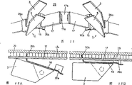
Clamping device of expressing at Fig. 9 and clamping device shown in Figure 8 are similar, and it is arranged on the rail mounted base plate 17, and this base plate is vertically having a plurality of latched positions 18 and two tracks 19.Two anchor clamps 1 are installed on these two long rails with longitudinal movement.For these two anchor clamps are rigidly fixed on the base plate, these anchor clamps have the lock tab 20 that can enter in the locking device 18.For two anchor clamps are vertically moved along two tracks 19, two tracks 19 also include guider 16, and these guiders 16 are connected securely with two front sheets 11.
Form with front side perspective in Figure 10 illustrates the state of clamping device shown in Figure 9 when deviating from, so as to represent better these anchor clamps how can by shown in the direction of arrow vertically move along base plate 17.Can clamping hang narrow object with Fig. 9 and clamping device shown in Figure 10, as broom, shovel or a pair of skis, also can the wide or thick object of clamping, as a sled (Snow-board).The advantage of this clamping device is, hangs on the frame at a traditional skiing equipment and can hang skis, can hang sled again simultaneously, does not hang different sports apparatus and different clamping devices need be set.This advantage also is applicable to hanging home appliances, instrument, garden tool set etc. naturally.
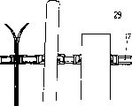
Similar with Fig. 9 and Figure 10, also be shown with a clamping device among Figure 11, this clamping device is vertically gone up removable and fixing along a guide tracked guide plate 17.Clamping device among Figure 11 comprises two anchor clamps 1 simultaneously.Each of these two anchor clamps 1 is respectively arranged with the longitudinally extending wallboard 3 and 5 of two flexibilities, in order to be clamped in an object of placing therebetween, as a pair of skis.These two anchor clamps are installed on the longitudinally extending rail mounted base plate 17.For clearly expression, disconnect from the centre this base plate 17, wherein, it is interconnective by the interruption section 17b that dots that separated two orbital segments are actually.Yet, see that by the centre Figure 11 also illustrates two anchor clamps 1 with different perspective form, in fact, whole base plate 17 is stretched flat.In addition, rail mounted base plate 17 is fixed on the rear wall 29 by dorsal part brace 17a.
With Fig. 9 with shown in Figure 10 that situation is set is similar, two anchor clamps 1 also are located on the guide plate 16, this guide plate 16 have one be positioned at the front side, clamp the guide section 20b of track 17 up and down, so that can be along base plate 17 resting guide 16 with longitudinal movement.
As from can finding out Figure 12 a and Figure 12 b, guide section 20b is an oblique angle with respect to guide plate 16, will further specify this oblique angle situation by Figure 12 a and Figure 12 b below.In addition, guide plate 16 also comprises a canned paragraph 20a who is positioned at dorsal part, so that guide plate 16 is clamped on the rail mounted base plate 17.
Now describe Figure 11 and the operation principle that header board or base plate 16 are set shown in Figure 12 in detail by Figure 12 a and Figure 12 b.In Figure 12 a, gripping section 20a puts from base plate 17, and in view of the above, guide section 20b is substantially perpendicular to track 17 configurations, and the result causes the enlarged diameter of the gathering sill on the guide section 20b.In view of the above, anchor clamps can vertically move along track 17.Anchor clamps just for example move towards the direction of another anchor clamps 1 of clamping device, or another anchor clamps 1 that break away from clamping device are towards oppositely moving, and this will decide according to the size for the treatment of the clamping object between base.
For anchor clamps 1 are securely fixed on the track 17, just must upwards promote canned paragraph 20a on the track 17, for example, just canned paragraph 20a can be inserted on the track securely by the clamp-type structure of canned paragraph 20a.Shown in Figure 12 b, guide section 20b present position is an oblique angle with respect to track 17, so also can make the interior clamping action that produces in zone of guide section.Become the reason of clamping action to be, because it is in tilted layout, the gathering sill on the guide section 20b dwindles to some extent with respect to track 17.Therefore, even above-mentioned anchor clamps under the bigger situation of strength, can not be along the longitudinal movement in the middle of being positioned at owing to treat the object of clamping again.If will unclamp anchor clamps again, only need simply canned paragraph 20a to be lifted to de-orbit 17, in view of the above, also eliminated the clamping action of guide section 20b.
Expression has the routine version of another enforcement of the anchor clamps 1 that constitute according to the present invention in Figure 13 a and Figure 13 b, wherein, Figure 13 a expresses two mutual opposed anchor clamps 1 with the form of front view, and Figure 13 b then one of expresses in two anchor clamps with the form of vertical view.Anchor clamps 1 shown in Figure 13 a and Figure 13 b are similar with the anchor clamps shown in Figure 11, Figure 12 a and Figure 12 b, and being applicable to can be along the mobile continuously setting of a track 17.Anchor clamps have a fixed body 11 that is positioned at rear side, are respectively equipped with two legs 3 and 5 in the holddown groove 11a of this fixed body 11 and 11b.Leg 3 and 5 front side have the bar formula portion section that constitutes according to the present invention, so that an object is clamped between two anchor clamps.These two legs 3 and 5 are for example made by rubber elastic material.In view of the above, when the object for the treatment of clamping was inserted from bottom to top, a little upward deflected to make two legs, then, and when decontroling this object, because two legs 3 and 5 downward bias then clamp object again.
Similar with the anchor clamps shown in Figure 11, Figure 12 a and Figure 12 b, the anchor clamps shown in Figure 13 a and Figure 13 b have a guide plate 16 respectively.Fixed body 11 for example is fixed on this guide plate 16 by screw jockey 23.Particularly from Figure 13 b seen such, screw 23a screws on the fixed body 11 in the corresponding nut 23b.Guide plate 16 also has a guide section 20b and a canned paragraph 20a who is positioned at dorsal part respectively.This canned paragraph 20a has a fixedly projection 20c, is fixed on the track 17 in order to guide plate 16 is stretched into.If anchor clamps are vertically moved, similar with situation shown in Figure 12 a, be raised to by fixing projection 20c and make canned paragraph 20a offset track 17 on the track seamed edge.When the time comes, the guide plate swing departs from, and till guide section 20b was substantially perpendicular to track 17, in view of the above, anchor clamps just can longitudinally move.
In Figure 14 a and Figure 14 b, represent to have the cross section of guide plate 16 respectively with the form of front view and vertical view, fixed body itself wherein is not shown.In Figure 14 a and Figure 14 b, be illustrated in gathering sill on the guide section 20b with piece number 20d.
In Figure 15 a, 15b and Figure 15 c, schematically show following situation: in order to hang for example bar-shaped object, at first be how two anchor clamps are located, then how object itself hung.
In Figure 15 a, object 31 by near with two legs 3 that are positioned at anchor clamps 1 and 5 on, another anchor clamps 1 then move to the object 31 for the treatment of clamping by the deflection of guide plate, till object is respectively near two legs 3 and 5.
Shown in Figure 15 b, object is inserted between two anchor clamps 1 from bottom to top along the direction of arrow.At this moment, two leg 3 and 5 upward deflects because of having caoutchouc elasticity.
Shown in 15c, object 31 is decontroled, in view of the above, this object is moved down again because of its deadweight, thereby make two legs 3 and 5 because of there being its caoutchouc elasticity to promote simultaneously downwards, till object 31 is clamped between leg 3 and 5.Can see clearly that from Figure 15 c because object 31 is on the one hand between two legs 3, and be subjected to dual clamping on the other hand between two legs, institute is so that object 31 can not run-off the straight or deflections.
In Figure 16, also represent the guide rail 17 that has one to be located on the face wall 29 with the form of front view.A plurality of clamping device or anchor clamps that constitute according to the present invention are arranged on this guide rail 17.Can find out clearly that in Figure 16 the infinitely side by anchor clamps vertically moves, but the various objects of clamping with different size or different-thickness.Therefore, but but for example broad of clamping or the thicker a pair of skis of plate clamping, but also pipe of clamping or the like.Certainly,, when the width of object is big, also bigger width can be arranged according to anchor clamps of the present invention according to the width situation of object, so, as Figure 13 and anchor clamps shown in Figure 14 5 centimetres, width more than 10 centimetres or 10 centimetres just can be arranged.
The structure of another embodiment of expression guide plate or base plate 16 in Figure 17 a and Figure 17 b, but the clamping device of establishing thereon is not shown.This guide plate or base plate can make anchor clamps infinitely move and reset along guide rail 17 in addition.Figure 17 a illustrates this version with the form of perspective view, and Figure 17 b then illustrates this guide plate with the form of vertical view.
Guide plate or base plate 16 also are to be fixed on the long rails 17 by the canned paragraph 20a of dorsal part and guide section 20b.The mobility of guide plate 16 or stationarity realize by an eccentric rod 41.This eccentric rod can be inserted in the opening 43 of guide plate 16.As particularly appreciable in Figure 17 a, eccentric rod 41 can forward closing position to from the enable possition.Eccentric structure (referring to Figure 17 b) by eccentric rod 41 perhaps is clamped in guide plate 16 on the track 17, perhaps makes guide plate obtain discharging.
When eccentric rod was in the enable possition, guide plate or base plate 16 just can move on track 17, after eccentric rod 41 is rotated guide plate 16 were clamped on the track 17 securely.The advantage of this guide plate 16 has been to save the upset or the oscillating motion of guide plate 16 shown in Figure 13 a and Figure 13 b.Also can guarantee in view of the above, when anchor clamps being positioned on the object to be hung, two distances between the anchor clamps no longer be enlarged owing to the backswing of anchor clamps to be clamped.
Passing the imperial examinations at the provincial level at Fig. 1 to Figure 17, the clamping device that constitutes according to the present invention is shown only is to be used to illustrate the present invention to example, and available various mode corrects certainly, variation or replenish.According to the present invention, whether device neither be important by metal or plastic production this point.The present invention also is not limited to the anchor clamps that only have two support sections or a bearing-surface, and particularly as shown in Figure 7, this anchor clamps also can have a plurality of sections of clamping object.A plurality of anchor clamps can also be set, so that the big object of clamping weight reliably on different horizontal planes.
The main points of invention are that be provided with a clamping component or anchor clamps at least, these anchor clamps have at least two clamping part sections or a flat clamping face.
Claims (18)
1. be used to hang particularly the device of longitudinally extending object basically, this device comprises at least one clamping component, this member can be towards a wall or the motion of another clamping component, so that the deadweight by described object is clamped in this object between clamping component and wall or another clamping component securely, it is characterized in that, at least one clamping component (1), it comprises at least two in the spaced support section (3 of vertical direction, 5) and/or the supporting area on the plane of at least one setting (4), so that be bonded on the side of object (30), and object shifted onto wall (21) go up or shift onto on another clamping component (1) in clamping or when hanging object.
2. according to the described device of claim 1, it is characterized in that at least one clamping component (1) is can or can swingingly be provided with towards another clamping component (1) that is contained on the flat component (17) towards wall (21) basically.
3. according to claim 1 or 2 described devices, it is characterized in that clamping component is set as and can swings, each that makes at least two portion's sections (3,5) or plane area (4) can be respectively around two axle center (8,10; 8a, 10a), be each section (3,5) can be around a specific axle center or plane (4) in the mode of parallelogram around two axis swings, make this become moving downward of a curve towards wall (21) or towards the motion of the clamping object (30) of another clamping component (1).
4. according to described device one of in the claim 1 to 3, it is characterized in that, at least one clamping component (1) is anchor clamps, wherein, constitute portion's section (3,5) of these anchor clamps or its linkage section (4) with or plane area (4) be the portion's section that is used to clamp (3,5) or plane (4 of being arranged to be arranged essentially parallel on wall (21) or relative another clamping component (1)).
5. according to described device one of in the claim 1 to 4, it is characterized in that portion's section (3,5) or plane (4) one is the extending longitudinally structure with plate-type component (17) perpendicular.
6. according to described device one of in the claim 1 to 5, it is characterized in that, another clamping component (1) has at least one bearing-surface as supporting, extending longitudinally supporting or a flat bearing, treats that the object of clamping can be shifted onto in this supporting by that clamping component (1) on opposite.
7. according to described device one of in the claim 1 to 5, it is characterized in that, one of them clamping component (1) is arranged to the parallelogram anchor clamps, one of them limit (11) and plate-type component (17) are permanently connected, and its relative that limit (4) can be set as with it, and side direction is parallel to be moved and swing or to another clamping component (1) swing clamping object towards wall (21).
8. according to described device one of in the claim 1 to 7, it is characterized in that anchor clamps (1) to small part is to be made by material flexibility or flexible, so that relative edge (4) can be swung to a side (11).
9. according to described device one of in the claim 1 to 8, it is characterized in that, in the anchor clamps (1) of parallelogram sturcutre, do not have can be free movable relative edge (4), so that form one have in the front side opening like the U-shaped anchor clamps, these anchor clamps have two be in distal portion, mutually and perpendicular plate-type component (17) stretch, rib shape or stripes section (3,5).
10. according to the described device of claim 9, it is characterized in that, rib shape portion section (3,5), is warpage upwards, form the Gu Xingbi (3b, 5b) of fixture type with each, and these two walls are almost configuration up and down vertically under unclamped state.
11. according to the described device in one of claim 9 or 10, it is characterized in that, have a fixed body (11) of being made by sturdy material that is positioned at dorsal part like the anchor clamps (1) of U-shaped, two U-shaped legs (3,5) are fixed in this fixed body (11), and two are parallel to each other.The U-shaped leg is to be made by material flexibility or caoutchouc elasticity, so as to make two lay respectively at the leg end be preferably plane or stripes Duan Kexiang another or from another clamping component or to another or from another anchor clamps swing.
12. according to described device one of in the claim 1 to 11, it is characterized in that portion's section (3,5) and/or plane area (4) to small part are arranged to surperficial hacking, or cover the material that one deck reduces sliding friction thereon.
13. according to described device one of in the claim 1 to 12, it is characterized in that, another clamping component (1) and relative another clamping component (1) be set as plane symmetry basically and be located at its opposite, two clamping components then are arranged to swing in opposite directions.
14. according to described device one of in the claim 1 to 12, it is characterized in that,, be provided with a plurality of clamping components in vertical direction towards a wall or towards other clamping components of special similar amt.
15. according to describedly one of in the claim 1 to 13 comprise one or more devices, be used to hang have different-thickness or different size, the equipment of longitudinally extending object basically particularly, it is characterized in that, at least one clamping component (1) preferably can add can being fixed on another board-like or rail mounted member (17), so that the object of clamping different-thickness or width of infinitely vertically moving with unclamping again.
16. according to the described equipment of claim 15, it is characterized in that, each of anchor clamps is located on the guide plate (16) in the clamping structure (1) that at least one or two match, described guide plate (16) have at least more than one side or with below clamping plates formula or another member of rail mounted (17) vertically with clamping of its biasing or interval or fixture (20 a, 20c; 41), so that guide plate (16) releasably is fixed on another member board-like or rail mounted (17) again.
17. according to the described equipment of claim 16, it is characterized in that, guide rail on guide section and another member (17) is an oblique angle, the gathering sill of establishing at the last promising guide rail (17) of guide section (20b) (20d), its size is to be provided with like this, at guide plate (16) released and pendulum from and at guide section (20b) when being substantially perpendicular to track, guide plate can move freely along another member (17), but clamping or fixture (20a, 20c) is fixed on another member (17) to guide plate when going up, track is almost to be clamped in the gathering sill (20d) at least.
18. according to the described equipment of claim 16, it is characterized in that, clamp or fixture has an eccentric stiffener (41), by this eccentric stiffener (41) by rotate or clamp can make guide plate (16) releasably be fixed on board-like again or another member of rail mounted (17) on.
Applications Claiming Priority (2)
| Application Number | Priority Date | Filing Date | Title |
|---|---|---|---|
| CH01600/93A CH689863A5 (en) | 1993-05-27 | 1993-05-27 | Device for hanging placing a longitudinally extended object. |
| CH1600/93-2 | 1993-05-27 |
Publications (1)
| Publication Number | Publication Date |
|---|---|
| CN1111443A true CN1111443A (en) | 1995-11-08 |
Family
ID=4214215
Family Applications (1)
| Application Number | Title | Priority Date | Filing Date |
|---|---|---|---|
| CN94190434.2A Pending CN1111443A (en) | 1993-05-27 | 1994-05-11 | Device for suspending a longitudinally extended object |
Country Status (20)
| Country | Link |
|---|---|
| US (1) | US5601196A (en) |
| EP (1) | EP0652723B1 (en) |
| JP (1) | JPH07509392A (en) |
| CN (1) | CN1111443A (en) |
| AT (1) | ATE148321T1 (en) |
| AU (1) | AU676321B2 (en) |
| BR (1) | BR9405566A (en) |
| CA (1) | CA2141024A1 (en) |
| CH (1) | CH689863A5 (en) |
| DE (1) | DE59401707D1 (en) |
| DK (1) | DK0652723T3 (en) |
| ES (1) | ES2101529T3 (en) |
| FI (1) | FI105444B (en) |
| GR (1) | GR3023299T3 (en) |
| HU (1) | HU217929B (en) |
| MX (1) | MX9403876A (en) |
| PH (1) | PH31188A (en) |
| RU (1) | RU2112412C1 (en) |
| TW (1) | TW300274B (en) |
| WO (1) | WO1994027487A1 (en) |
Families Citing this family (22)
| Publication number | Priority date | Publication date | Assignee | Title |
|---|---|---|---|---|
| AU2760997A (en) * | 1996-05-30 | 1998-01-05 | Texpart-Handels Ag | Device for holding or suspending objects |
| US6196397B1 (en) * | 1998-01-06 | 2001-03-06 | Burton Corporation | Rack for holding a gliding board |
| DE10047352C1 (en) * | 2000-09-25 | 2002-06-06 | Vermop Salmon Gmbh | Connection part for a cleaning trolley |
| US6942094B2 (en) * | 2002-12-09 | 2005-09-13 | Wmc Holding Incorporated | Sportboard storage apparatus |
| US6827226B2 (en) | 2002-12-09 | 2004-12-07 | Wmc Holdings Incorporated | Storage apparatus for sportboards with variable widths |
| US6935517B1 (en) * | 2003-06-09 | 2005-08-30 | Robert Reed | Snowboard support and display rack |
| CA2470272C (en) * | 2004-06-08 | 2009-12-22 | Rudy Pfeiffer | Apparatus for storing a recreational board |
| US20080083684A1 (en) * | 2004-08-23 | 2008-04-10 | Rudy Pfeiffer | Apparatus for storing a recreational board |
| US7374051B2 (en) * | 2005-02-24 | 2008-05-20 | Steven Garceau | Elongated board vertical holding device |
| US7503459B2 (en) * | 2005-04-27 | 2009-03-17 | Normark Innovations, Inc. | Device for storing fishing rods and other tools |
| US20070034762A1 (en) * | 2005-08-15 | 2007-02-15 | Russell White | Variable article holder |
| US8662321B1 (en) * | 2009-07-02 | 2014-03-04 | Julie Raper | Sports equipment rack, systems and methods of storing or displaying sports equipment |
| US8123051B2 (en) * | 2009-07-20 | 2012-02-28 | Target Brands, Inc. | Display apparatus for securely displaying a product |
| CN103536259A (en) * | 2013-09-30 | 2014-01-29 | 李云峰 | Clamp holder for hanging mop |
| CA2884045A1 (en) * | 2014-03-07 | 2015-09-07 | Evriholder Products, Llc | Device for securing enlongate articles |
| RU2630206C2 (en) * | 2015-12-08 | 2017-09-05 | Анатолий Степанович Дресвянкин | Sports-hiking waist belt |
| CN107380657B (en) * | 2017-07-07 | 2022-12-30 | 嘉兴炬星数字科技有限公司 | Loading and unloading mechanism in long-strip-shaped aluminum profile positioning device |
| DE202018105795U1 (en) | 2018-10-10 | 2018-11-05 | Leonhard Maier | Hanging device for the hanging arrangement of objects |
| NO345650B1 (en) * | 2020-01-15 | 2021-05-31 | Jan Otto Halseth | Ski suspension with wedge attachment |
| EP4029657A1 (en) | 2020-08-07 | 2022-07-20 | Techtronic Cordless GP | Modular storage system |
| US11884456B2 (en) | 2020-09-25 | 2024-01-30 | Techtronic Cordless Gp | Tool storage system |
| USD1025600S1 (en) | 2021-01-20 | 2024-05-07 | Techtronic Cordless Gp | Storage container |
Family Cites Families (38)
| Publication number | Priority date | Publication date | Assignee | Title |
|---|---|---|---|---|
| DE504185C (en) * | 1930-08-02 | Jakob Manger | Suspension device with eccentric clamping rollers | |
| US1306585A (en) * | 1919-06-10 | And george a | ||
| CH47092A (en) * | 1909-03-27 | 1910-06-01 | Emil Herrmann | Hanging device |
| FR500964A (en) * | 1919-04-26 | 1920-03-30 | Pierre Louis Commegrain | Clip for hanging towels |
| CH113521A (en) * | 1925-03-18 | 1926-01-16 | Eggmann Laesser Max | Holder for devices with handles or extensions. |
| US1609666A (en) * | 1926-03-20 | 1926-12-07 | Nels A Settevig | Broom holder |
| FR626467A (en) * | 1926-03-29 | 1927-09-07 | Device for suspending by their cylindrical handles brooms, feather dusters, brushes, swags and other similar articles | |
| FR687312A (en) * | 1929-01-14 | 1930-08-07 | Clip holder for hanging tools or objects with handles | |
| FR734104A (en) * | 1932-03-21 | 1932-10-17 | Brush holder | |
| US1958772A (en) * | 1932-05-14 | 1934-05-15 | Kenneth D Stewart | Article holder |
| US2370876A (en) * | 1944-01-29 | 1945-03-06 | Presly C Richardson | Hanger for slender articles |
| CH247405A (en) * | 1945-07-18 | 1947-03-15 | Pellet Marcel | Device for hanging objects such as brooms, tools, towels, etc. |
| GB641003A (en) * | 1948-09-21 | 1950-08-02 | Robert Bolton Durose | Improvements in holders for brush stales or other articles |
| US2661920A (en) * | 1951-02-26 | 1953-12-08 | Benjamin F Gochenour | Implement holding device |
| US2683891A (en) * | 1953-04-10 | 1954-07-20 | Eastern Venetian Blind Company | Drapery traverse rod assembly |
| CH342339A (en) * | 1956-03-28 | 1959-11-15 | Stadelmann Weber Elisabeth | Device for hanging up all kinds of equipment with handles |
| US2869209A (en) * | 1957-07-31 | 1959-01-20 | Kautzky Joe | Rod holding device |
| CH365501A (en) * | 1958-10-08 | 1962-11-15 | Weingartner Alfred | Holder for stick devices |
| US3161393A (en) * | 1963-08-09 | 1964-12-15 | Bror W Swanson | Utility clamp assembly |
| CA969889A (en) * | 1973-08-23 | 1975-06-24 | Hershel Stacy (Sr.) | Utility tree |
| CH619125A5 (en) * | 1978-04-06 | 1980-09-15 | Richard Staremberg | Device for holding skis |
| GB2038613A (en) * | 1979-01-03 | 1980-07-30 | Green M G | Article holder |
| US4591058A (en) * | 1984-05-10 | 1986-05-27 | Amstore Corporation | Slatboard |
| US4678151A (en) * | 1984-06-29 | 1987-07-07 | Ready Metal Manufacturing Company | Merchandise hanger for slotted wall display panel |
| DE8432710U1 (en) * | 1984-11-08 | 1985-06-20 | Bruns, Franz, 4834 Harsewinkel | Device holder |
| GB8517489D0 (en) * | 1985-07-10 | 1985-08-14 | Brookline Delta Ltd | Clip |
| US4852747A (en) | 1987-08-10 | 1989-08-01 | Geerpres, Inc. | Multiple tool holder assembly |
| US4763797A (en) * | 1987-08-14 | 1988-08-16 | Egan George E | Ski rack |
| US4798298A (en) * | 1987-10-30 | 1989-01-17 | Ursetta Chris H | Apparatus for gripping skis or like |
| SE460252B (en) * | 1988-02-10 | 1989-09-25 | Sparring Elfa Ab | BAERLIST FOR HAENGSKENOR |
| DE3818031A1 (en) * | 1988-05-27 | 1989-11-30 | Brauckmann & Proebsting | Device for securing tools |
| US5183164A (en) * | 1989-02-03 | 1993-02-02 | Snowboardlinik Und Handelsges M.B.H. | Clamping holder for suspending skis |
| US4988007A (en) * | 1990-06-19 | 1991-01-29 | Chiarot John B | Modular ski rack and mounting kit |
| DE4106351A1 (en) * | 1991-02-28 | 1992-09-03 | Bajo Trading Anstalt | Ski holder with profiled rail - has several spaced yokes forming holders with distance arm protruding at right angles and having locking arm adjoining at distance |
| ES1017497Y (en) * | 1991-04-04 | 1992-11-16 | Saint Genis, S.A. | FLEXIBLE CLAMP FOR SUPPORT OF HANDLES AND SIMILAR IN VERTICAL. |
| DE4314770C1 (en) * | 1993-05-05 | 1994-11-10 | Bajo Trading Anstalt | Holding device for stems and pipes of equipment |
| US5303831A (en) * | 1993-08-19 | 1994-04-19 | Carl Miller | Holder for brooms and the like |
| US5417335A (en) * | 1993-12-23 | 1995-05-23 | White; Steven M. | Apparatus and methods for suspending a pair of skis or the like |
-
1993
- 1993-05-27 CH CH01600/93A patent/CH689863A5/en not_active IP Right Cessation
-
1994
- 1994-05-11 WO PCT/CH1994/000087 patent/WO1994027487A1/en active IP Right Grant
- 1994-05-11 CA CA002141024A patent/CA2141024A1/en not_active Abandoned
- 1994-05-11 JP JP7500062A patent/JPH07509392A/en active Pending
- 1994-05-11 ES ES94914301T patent/ES2101529T3/en not_active Expired - Lifetime
- 1994-05-11 EP EP94914301A patent/EP0652723B1/en not_active Expired - Lifetime
- 1994-05-11 AT AT94914301T patent/ATE148321T1/en not_active IP Right Cessation
- 1994-05-11 US US08/379,454 patent/US5601196A/en not_active Expired - Lifetime
- 1994-05-11 CN CN94190434.2A patent/CN1111443A/en active Pending
- 1994-05-11 BR BR9405566-1A patent/BR9405566A/en not_active IP Right Cessation
- 1994-05-11 HU HU9500576A patent/HU217929B/en not_active IP Right Cessation
- 1994-05-11 DK DK94914301.0T patent/DK0652723T3/en active
- 1994-05-11 RU RU95107685A patent/RU2112412C1/en active
- 1994-05-11 AU AU66750/94A patent/AU676321B2/en not_active Ceased
- 1994-05-11 DE DE59401707T patent/DE59401707D1/en not_active Expired - Fee Related
- 1994-05-23 TW TW083104637A patent/TW300274B/zh active
- 1994-05-23 PH PH48315A patent/PH31188A/en unknown
- 1994-05-25 MX MX9403876A patent/MX9403876A/en not_active Application Discontinuation
-
1995
- 1995-01-27 FI FI950361A patent/FI105444B/en not_active IP Right Cessation
-
1997
- 1997-04-29 GR GR970400958T patent/GR3023299T3/en unknown
Also Published As
| Publication number | Publication date |
|---|---|
| ES2101529T3 (en) | 1997-07-01 |
| MX9403876A (en) | 1995-01-31 |
| AU6675094A (en) | 1994-12-20 |
| JPH07509392A (en) | 1995-10-19 |
| RU95107685A (en) | 1996-11-20 |
| FI950361A0 (en) | 1995-01-27 |
| HUT71168A (en) | 1995-11-28 |
| FI950361A (en) | 1995-03-21 |
| CA2141024A1 (en) | 1994-12-08 |
| FI105444B (en) | 2000-08-31 |
| WO1994027487A1 (en) | 1994-12-08 |
| PH31188A (en) | 1998-04-24 |
| EP0652723B1 (en) | 1997-01-29 |
| RU2112412C1 (en) | 1998-06-10 |
| US5601196A (en) | 1997-02-11 |
| GR3023299T3 (en) | 1997-07-30 |
| BR9405566A (en) | 1999-09-08 |
| TW300274B (en) | 1997-03-11 |
| HU9500576D0 (en) | 1995-04-28 |
| EP0652723A1 (en) | 1995-05-17 |
| HU217929B (en) | 2000-05-28 |
| AU676321B2 (en) | 1997-03-06 |
| ATE148321T1 (en) | 1997-02-15 |
| DK0652723T3 (en) | 1997-08-18 |
| CH689863A5 (en) | 1999-12-31 |
| DE59401707D1 (en) | 1997-03-13 |
Similar Documents
| Publication | Publication Date | Title |
|---|---|---|
| CN1111443A (en) | Device for suspending a longitudinally extended object | |
| US6389864B1 (en) | Heavy duty sheet bending brake | |
| US5799349A (en) | Surgical knee holder | |
| CN107432781A (en) | A kind of orthopaedics clamping device | |
| WO1989011893A1 (en) | An arrangement in a flexible sliding mat, if desired for use with an exerciser | |
| US20120277079A1 (en) | Exercise Apparatus and Associated Methods | |
| US11541271B2 (en) | Multi-functional exercise device | |
| US20040217532A1 (en) | Portable, adjustable vertical work holder device | |
| EP3177374B1 (en) | Standup paddle board core activator | |
| US7556594B2 (en) | Fitness device | |
| CN210813726U (en) | Collapsible and firm abdomen extension board | |
| CN103432717A (en) | Elliptical machine | |
| CN108756182A (en) | A kind of construction and decoration PVC plastic adhesive floor automatic processing equipment | |
| CN110051120A (en) | A kind of multifunctional office articles bogey | |
| CN209828130U (en) | Finger rehabilitation device for children | |
| US20080296090A1 (en) | Gripping Apparatus | |
| RU194992U1 (en) | Wheelchair accessible device | |
| CN206979859U (en) | A kind of site safety band hanger | |
| CN212141372U (en) | But dance barre that horizontal rotation was accomodate | |
| NO311917B1 (en) | Suspension device for an elongated object | |
| CN217922964U (en) | Adjustable kerbstone portable clamp | |
| CN213677855U (en) | A fixing device is used in transportation for building polyurethane composite sheet | |
| CN214216051U (en) | Bicycle handlebar fixing device | |
| CN218714992U (en) | Scaffold collet rapid Assembly device for building | |
| CN213295496U (en) | Flexible workpiece hoisting self-rotating mechanism |
Legal Events
| Date | Code | Title | Description |
|---|---|---|---|
| C06 | Publication | ||
| PB01 | Publication | ||
| C10 | Entry into substantive examination | ||
| SE01 | Entry into force of request for substantive examination | ||
| C02 | Deemed withdrawal of patent application after publication (patent law 2001) | ||
| WD01 | Invention patent application deemed withdrawn after publication |