CN111106300A - Battery unit cell module - Google Patents
Battery unit cell module Download PDFInfo
- Publication number
- CN111106300A CN111106300A CN201910088350.0A CN201910088350A CN111106300A CN 111106300 A CN111106300 A CN 111106300A CN 201910088350 A CN201910088350 A CN 201910088350A CN 111106300 A CN111106300 A CN 111106300A
- Authority
- CN
- China
- Prior art keywords
- current collector
- width direction
- electrode assembly
- battery cell
- bent
- Prior art date
- Legal status (The legal status is an assumption and is not a legal conclusion. Google has not performed a legal analysis and makes no representation as to the accuracy of the status listed.)
- Granted
Links
Images


Classifications
-
- H—ELECTRICITY
- H01—ELECTRIC ELEMENTS
- H01M—PROCESSES OR MEANS, e.g. BATTERIES, FOR THE DIRECT CONVERSION OF CHEMICAL ENERGY INTO ELECTRICAL ENERGY
- H01M10/00—Secondary cells; Manufacture thereof
- H01M10/04—Construction or manufacture in general
- H01M10/045—Cells or batteries with folded plate-like electrodes
- H01M10/0454—Cells or batteries with electrodes of only one polarity folded
-
- H—ELECTRICITY
- H01—ELECTRIC ELEMENTS
- H01M—PROCESSES OR MEANS, e.g. BATTERIES, FOR THE DIRECT CONVERSION OF CHEMICAL ENERGY INTO ELECTRICAL ENERGY
- H01M10/00—Secondary cells; Manufacture thereof
- H01M10/04—Construction or manufacture in general
- H01M10/0431—Cells with wound or folded electrodes
-
- H—ELECTRICITY
- H01—ELECTRIC ELEMENTS
- H01M—PROCESSES OR MEANS, e.g. BATTERIES, FOR THE DIRECT CONVERSION OF CHEMICAL ENERGY INTO ELECTRICAL ENERGY
- H01M50/00—Constructional details or processes of manufacture of the non-active parts of electrochemical cells other than fuel cells, e.g. hybrid cells
- H01M50/50—Current conducting connections for cells or batteries
- H01M50/528—Fixed electrical connections, i.e. not intended for disconnection
-
- H—ELECTRICITY
- H01—ELECTRIC ELEMENTS
- H01M—PROCESSES OR MEANS, e.g. BATTERIES, FOR THE DIRECT CONVERSION OF CHEMICAL ENERGY INTO ELECTRICAL ENERGY
- H01M50/00—Constructional details or processes of manufacture of the non-active parts of electrochemical cells other than fuel cells, e.g. hybrid cells
- H01M50/10—Primary casings, jackets or wrappings of a single cell or a single battery
- H01M50/172—Arrangements of electric connectors penetrating the casing
- H01M50/174—Arrangements of electric connectors penetrating the casing adapted for the shape of the cells
- H01M50/176—Arrangements of electric connectors penetrating the casing adapted for the shape of the cells for prismatic or rectangular cells
-
- H—ELECTRICITY
- H01—ELECTRIC ELEMENTS
- H01M—PROCESSES OR MEANS, e.g. BATTERIES, FOR THE DIRECT CONVERSION OF CHEMICAL ENERGY INTO ELECTRICAL ENERGY
- H01M50/00—Constructional details or processes of manufacture of the non-active parts of electrochemical cells other than fuel cells, e.g. hybrid cells
- H01M50/50—Current conducting connections for cells or batteries
- H01M50/531—Electrode connections inside a battery casing
- H01M50/536—Electrode connections inside a battery casing characterised by the method of fixing the leads to the electrodes, e.g. by welding
-
- H—ELECTRICITY
- H01—ELECTRIC ELEMENTS
- H01M—PROCESSES OR MEANS, e.g. BATTERIES, FOR THE DIRECT CONVERSION OF CHEMICAL ENERGY INTO ELECTRICAL ENERGY
- H01M50/00—Constructional details or processes of manufacture of the non-active parts of electrochemical cells other than fuel cells, e.g. hybrid cells
- H01M50/50—Current conducting connections for cells or batteries
- H01M50/543—Terminals
- H01M50/547—Terminals characterised by the disposition of the terminals on the cells
- H01M50/55—Terminals characterised by the disposition of the terminals on the cells on the same side of the cell
-
- H—ELECTRICITY
- H01—ELECTRIC ELEMENTS
- H01M—PROCESSES OR MEANS, e.g. BATTERIES, FOR THE DIRECT CONVERSION OF CHEMICAL ENERGY INTO ELECTRICAL ENERGY
- H01M50/00—Constructional details or processes of manufacture of the non-active parts of electrochemical cells other than fuel cells, e.g. hybrid cells
- H01M50/50—Current conducting connections for cells or batteries
- H01M50/543—Terminals
- H01M50/552—Terminals characterised by their shape
- H01M50/553—Terminals adapted for prismatic, pouch or rectangular cells
-
- H—ELECTRICITY
- H01—ELECTRIC ELEMENTS
- H01M—PROCESSES OR MEANS, e.g. BATTERIES, FOR THE DIRECT CONVERSION OF CHEMICAL ENERGY INTO ELECTRICAL ENERGY
- H01M2220/00—Batteries for particular applications
- H01M2220/20—Batteries in motive systems, e.g. vehicle, ship, plane
-
- Y—GENERAL TAGGING OF NEW TECHNOLOGICAL DEVELOPMENTS; GENERAL TAGGING OF CROSS-SECTIONAL TECHNOLOGIES SPANNING OVER SEVERAL SECTIONS OF THE IPC; TECHNICAL SUBJECTS COVERED BY FORMER USPC CROSS-REFERENCE ART COLLECTIONS [XRACs] AND DIGESTS
- Y02—TECHNOLOGIES OR APPLICATIONS FOR MITIGATION OR ADAPTATION AGAINST CLIMATE CHANGE
- Y02E—REDUCTION OF GREENHOUSE GAS [GHG] EMISSIONS, RELATED TO ENERGY GENERATION, TRANSMISSION OR DISTRIBUTION
- Y02E60/00—Enabling technologies; Technologies with a potential or indirect contribution to GHG emissions mitigation
- Y02E60/10—Energy storage using batteries
-
- Y—GENERAL TAGGING OF NEW TECHNOLOGICAL DEVELOPMENTS; GENERAL TAGGING OF CROSS-SECTIONAL TECHNOLOGIES SPANNING OVER SEVERAL SECTIONS OF THE IPC; TECHNICAL SUBJECTS COVERED BY FORMER USPC CROSS-REFERENCE ART COLLECTIONS [XRACs] AND DIGESTS
- Y02—TECHNOLOGIES OR APPLICATIONS FOR MITIGATION OR ADAPTATION AGAINST CLIMATE CHANGE
- Y02P—CLIMATE CHANGE MITIGATION TECHNOLOGIES IN THE PRODUCTION OR PROCESSING OF GOODS
- Y02P70/00—Climate change mitigation technologies in the production process for final industrial or consumer products
- Y02P70/50—Manufacturing or production processes characterised by the final manufactured product
Abstract
The invention relates to a battery unit and a battery module, wherein the battery unit comprises an electrode assembly (1) and a battery module, wherein the electrode assembly comprises a first electrode and a second electrode which have opposite polarities, the first electrode and the second electrode respectively comprise a coating part and an uncoated part, the uncoated part is positioned at the end part of a coating area along the length direction of the electrode assembly (1), and a tab (11) is formed; two terminals provided on the top of the electrode assembly (1); the two current collectors are used for electrically connecting the tabs (11) on the two sides of the electrode assembly (1) with the terminals on the same side respectively; at least one end of at least one current collector along the width direction of the electrode assembly (1) is of a flat plate structure, the tab (11) is bent and then coated with the flat plate structure from the outer side, and the two sides of the flat plate structure along the length direction are attached to the tab (11).
Description
Technical Field
The invention relates to the technical field of batteries, in particular to a battery unit and a battery module.
Background
In recent years, rechargeable batteries have been widely used to power high-power devices, such as electric vehicles and the like. Rechargeable batteries achieve greater capacity or power by connecting multiple battery cells in series or parallel.
The conventional battery unit is provided with an electrode assembly in a shell, the electrode assembly is formed by overlapping and winding a positive electrode plate, a diaphragm and a negative electrode plate, the positive electrode plate and the negative electrode plate respectively comprise a coating part and an uncoated part, the uncoated part forms a tab, and the tabs on two sides of the electrode assembly are respectively connected with the positive and negative poles on the top of the shell through a current collector.
In the related art known by the inventor, the current collectors on both sides of the electrode assembly are bent to improve the reliability of welding and fixing with the tabs by increasing the structural strength of the current collectors, but the current collectors and the tabs are fixed by occupying larger space on both sides of the electrode assembly, and the winding space is reduced under the condition that the volume of a battery unit is fixed, so that the energy density of the battery is reduced.
Disclosure of Invention
The embodiment of the invention provides a battery unit and a battery module, which can effectively improve the energy density of a battery.
According to an aspect of the present invention, there is provided a battery cell including:
an electrode assembly including first and second electrodes having opposite polarities, each of the first and second electrodes including a coated portion and an uncoated portion, the uncoated portion being located at an end of the coated region in a length direction of the electrode assembly and forming a tab;
two terminals provided at the top of the electrode assembly; and
the two current collectors are used for respectively and electrically connecting the lugs on the two sides of the electrode assembly with the terminals on the same side;
at least one end of at least one current collector along the width direction of the electrode assembly is of a flat plate structure, the tab is wrapped by the flat plate structure from the outer side after being bent, and two sides of the flat plate structure along the length direction are attached to the tab.
In some embodiments, the battery cell includes at least two electrode assemblies, the two current collectors include a first current collector and a second current collector respectively located at two sides of each electrode assembly, one end of each of the first current collector and the second current collector in the width direction is a flat plate structure, and the other end of each of the first current collector and the second current collector is provided with a bending part folded back towards the opposite side.
In some embodiments, the respective bent portions are located at the same side or different sides of the electrode assembly in the width direction.
In some embodiments, the end of each electrode assembly corresponding to the flat plate structure protrudes in the length direction relative to the end corresponding to the bent portion, each of the two current collectors includes a main body portion, the bent portion is disposed at the end of the main body portion in the width direction, the main body portion is bent at a position adjacent to the two electrode assemblies to form a step, and the step is adapted to the protruding direction and size of the electrode assembly.
In some embodiments, the two current collectors include a first current collector and a second current collector respectively located at both sides of each electrode assembly, and both ends of one of the first current collector and the second current collector in the width direction are flat plate structures.
In some embodiments, the battery cell includes an electrode assembly, the first end of the first current collector in the width direction is a flat plate structure, the second end is provided with a bent portion folded back toward the first end, and both ends of the second current collector in the width direction are flat plate structures.
In some embodiments, the battery cell includes at least two electrode assemblies, the first current collector is provided with bent portions at both ends in the width direction thereof, and the second current collector is of a flat plate structure at both ends in the width direction thereof.
In some embodiments, the battery cell includes at least two electrode assemblies, wherein the tabs of each electrode assembly are led out from the current collector along two sides of the width direction, and the tabs on the two sides are folded back without overlapping parts in the width direction.
In some embodiments, the battery unit includes at least two electrode assemblies, the tabs of each electrode assembly are led out from the current collector along two sides of the width direction, a plurality of tabs are arranged along the height direction of the current collector on at least one side, and the tabs on the same side are staggered along the height direction.
In some embodiments, the current collector comprises:
a terminal connection part located at the top of the electrode assembly and configured to connect the terminals;
a main body part located at a side surface of the electrode assembly in a length direction; and
a bent portion provided at an end of the main body portion in the width direction and configured to connect tabs;
the tab is bent from the outside to cover the bent part, and the bent part is folded and then attached to the main body part.
In some embodiments, a position where the terminal connecting portion and the main body portion are connected is provided with a reinforcing rib.
In some embodiments, the top surface of the bending portion is spaced apart from the terminal connecting portion, and a notch is formed at the top of the connecting position of the main body portion and the bending portion.
In some embodiments, the battery cell further includes a cap plate disposed on the top of the electrode assembly, and an end of the main body portion above the notch in the width direction is flush with an outer edge of the cap plate; and/or
The end of the main body portion below the notch in the width direction extends to the inner side surface of the tab root.
In some embodiments, the terminal connecting portion, the body portion, and the bent portion are integrally molded.
In some embodiments, at least one side of the current collector in the width direction is provided with a bent portion folded back toward the opposite side, and a root of the bent portion is retracted inward by a predetermined distance with respect to an end edge of the current collector in the width direction.
According to another aspect of the present invention, there is provided a battery module including:
a housing; and
in the battery unit of the above embodiment, the battery units are disposed in the case and arranged side by side in the width direction.
Based on the technical scheme, in the battery unit according to one embodiment of the invention, at least one end of at least one current collector along the width direction of the electrode assembly is of a flat plate structure, the tab is bent and then is coated with the flat plate structure from the outside, and two sides of the flat plate structure along the length direction are both attached to the tab. The battery unit can reduce the space occupied by the lug and the current collector connecting structure at the side end of the electrode assembly, and can increase the winding space, thereby effectively improving the energy density of the battery unit.
Drawings
The accompanying drawings, which are included to provide a further understanding of the invention and are incorporated in and constitute a part of this application, illustrate embodiment(s) of the invention and together with the description serve to explain the invention without limiting the invention. In the drawings:
fig. 1 is a perspective view of a bent portion of a current collector in an unfolded state in one embodiment of a battery cell of the present invention;
fig. 2 is a schematic structural view illustrating connection of a current collector and a cap plate in the battery cell shown in fig. 1;
FIG. 3 is a front view of the battery cell of FIG. 1;
FIG. 4 is a sectional view A-A of FIG. 3;
fig. 5 and 6 are enlarged views of the battery cell shown in fig. 4 at B and C, respectively;
fig. 7 is a perspective view of a folded portion of a current collector in the battery cell of fig. 1 in a folded-back state;
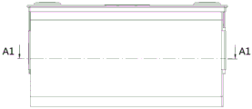
FIG. 8 is a front view of the battery cell of FIG. 7;
FIG. 9 is a cross-sectional view A1-A1 of FIG. 8;
FIGS. 10 and 11 are enlarged views at B1 and B2, respectively, in FIG. 9;
fig. 12A and 12B are a perspective view and a front view, respectively, of a first current collector without a notch;
fig. 13A and 13B are a perspective view and a front view, respectively, of a first current collector provided with a notch;
FIGS. 13C and 13D are cross-sectional views D-D and E-E, respectively, of FIG. 13B;
fig. 14 is a schematic view of a fusing structure disposed on a current collector corresponding to a positive electrode;
fig. 15 and 16 are schematic views of tabs welded at HJ1 and HJ2, respectively, of the battery cell of fig. 1;
fig. 17 is a perspective view of a folded portion of a current collector in another embodiment of a battery cell of the present invention;
fig. 18 is a perspective view of the folded portion of the current collector in the battery cell of fig. 17 in an unfolded state;
FIG. 19 is a front view of the battery cell of FIG. 17;
FIG. 20 is a cross-sectional view F-F of the battery cell shown in FIG. 17;
fig. 21 and 22 are enlarged views of the battery cell G and H shown in fig. 20, respectively;
fig. 23 is a perspective view of a folded portion of a current collector in a further embodiment of a battery cell of the present invention;
fig. 24 is a perspective view of the battery cell shown in fig. 23 with the bent portions of the current collectors in an unfolded state;
FIG. 25 is a front view of the battery cell of FIG. 23;
FIG. 26 is a J-J cross-sectional view of the battery cell shown in FIG. 25;
fig. 27 and 28 are enlarged views of the battery cell shown in fig. 26 at K and L, respectively.
Description of the reference numerals
1. An electrode assembly; 11. a tab; 12. a protective sheet; 2. a first current collector; 21. a bending section; 22. a terminal connecting portion; 221. a groove; 23. a main body portion; 231. a step; 24. reinforcing ribs; 25. a notch; 3. a second current collector; 4. a first terminal; 5. a second terminal; 6. a cover plate; 61. an exhaust member; 62. a seal member; 7. and (4) supporting the base.
Detailed Description
The present invention is described in detail below. In the following paragraphs, different aspects of the embodiments are defined in more detail. Aspects so defined may be combined with any other aspect or aspects unless clearly indicated to the contrary. In particular, any feature considered to be preferred or advantageous may be combined with one or more other features considered to be preferred or advantageous.
The terms "first", "second", and the like in the present invention are merely for convenience of description to distinguish different constituent elements having the same name, and do not denote a sequential or primary-secondary relationship.
In addition, when an element is referred to as being "on" another element, it can be directly on the other element or be indirectly on the other element with one or more intervening elements interposed therebetween. In addition, when an element is referred to as being "connected to" another element, it may be directly connected to the other element or may be indirectly connected to the other element with one or more intervening elements interposed therebetween. Hereinafter, like reference numerals denote like elements.
In order to clearly describe the respective orientations in the following embodiments, the coordinate system in fig. 1, for example, defines the respective directions of the battery cell, and the x-direction represents the length direction of the battery cell; the y direction is perpendicular to the x direction in the horizontal plane and represents the width direction of the battery cell; the z-direction is perpendicular to a plane formed by the x-and y-directions and indicates a height direction of the battery cell. Based on this orientation definition, the descriptions of the orientations or positional relationships indicated as "upper," "lower," "top," "bottom," "front," "back," "inner," and "outer" are used merely to facilitate the description of the invention and do not indicate or imply that the device so referred to must have a particular orientation, be constructed and operated in a particular orientation, and therefore should not be considered as limiting the scope of the invention.
In order to make the improvement of the present invention clear to those skilled in the art, the overall structure of the battery cell will be described first.
Fig. 1 illustrates a schematic structural view of one embodiment of a battery cell of the present invention. The battery cell may include an electrode assembly 1, a cap plate 6, two terminals, and two current collectors. The electrode assembly 1 includes a first electrode and a second electrode of opposite polarities, for example, the first electrode is a positive electrode and the second electrode is a negative electrode. Each of the first and second electrodes includes a coated portion and an uncoated portion, which is located at the end of the coated region in the length direction of the electrode assembly 1 and forms a tab 11. The cover plate 6 is arranged on the top of the electrode assembly 1, the cover plate 6 is provided with a gas exhaust component 61 and a liquid injection hole, the gas exhaust component 61 is used for releasing gas in the battery unit to play a safety role, and the liquid injection hole is used for injecting electrolyte into the battery unit and is sealed through a sealing piece 62. Two terminals are provided at both ends of the top of the electrode assembly 1 in the length direction, and include a first terminal 4 and a second terminal 5 having opposite polarities. And the two current collectors are respectively used for electrically connecting the lugs 11 on the two sides of the electrode assembly 1 along the length direction with the terminals on the same side.
When the battery cell is used independently, a sub-case connected to the cap plate is further provided outside the electrode assembly 1, and the sub-case is filled with an electrolyte. When a plurality of battery units form a battery module, the battery module comprises a shell and a plurality of battery units, each battery unit is arranged in the shell and arranged side by side along the width direction and can be connected in parallel and/or in series, and each battery unit can be provided with a sub-shell independently or the sub-shell is omitted.
As shown in fig. 17, the electrode assembly 1 in the battery cell may be provided singly, suitable for a case where the thickness of each electrode after stacking is small.
As shown in fig. 1, when the thickness of each electrode after lamination is large, two or more independently wound electrode assemblies 1 may be provided in a battery cell, and tabs 11 corresponding to each electrode assembly 1 are respectively drawn from both sides of a current collector. When the winding thickness of the electrode assembly 1 is large, the size of the arc at the bottom is large, so that the space utilization rate of the electrode assembly 1 at the outer sides of the arcs at two sides of the bottom is low, the arc size can be reduced by splitting the electrode assembly into a plurality of electrode assemblies, the bottom space of a battery unit is fully utilized, the space waste is reduced, and the energy density of a battery core is increased. Moreover, the total thickness of the tab 11 is also reduced, which is also beneficial for bending after welding, and the length of the single tab 11 can be reduced.
In order to further improve the energy density of the battery cell, in some embodiments, at least one end of at least one current collector in the battery cell of the present invention along the width direction of the electrode assembly 1 is a flat plate structure, the tab 11 is bent and then wrapped around the flat plate structure from the outside, and both sides of the flat plate structure along the length direction are attached to the tab 11. As shown in fig. 5, the outer side surface of the upper flat plate structure of the current collector contacts the extended and folded portion of the tab 11, and the inner side surface contacts the root portion of the tab 11, and although a gap exists between the inner side surface of the current collector and the root portion of the tab 11 in fig. 5, the current collectors on both sides and the electrode assembly 1 are pressed in an actual product.
This embodiment sets up at least one end through the mass flow body into dull and stereotyped structure, and dull and stereotyped structure all laminates with utmost point ear 11 along length direction's both sides, can reduce the space that utmost point ear 11 and mass flow body coupling structure occupy at electrode subassembly 1 side, and multiplicable coiling space to effectively improve battery cell's energy density.
A plurality of embodiments will be described below according to the difference in the number and positions of the flat plate structures.
Fig. 1 to 16 are schematic structural views illustrating one embodiment of a battery cell according to the present invention. As shown in fig. 1, the battery cell 100 includes at least two electrode assemblies 1, the two current collectors include a first current collector 2 and a second current collector 3 respectively located at two sides of each electrode assembly 1 along the length direction, one end of each of the first current collector 2 and the second current collector 3 along the width direction is a flat plate structure, and the other end is provided with a bent portion 21.
As shown in fig. 1 and 2, the bent portion 21 of the first current collector 2 and the bent portion 21 of the second current collector 3 are located on opposite sides of the two electrode assemblies 1 in the width direction, and the bent portion 21 may be disposed at an angle, for example, 90 °, with respect to the main body portion 23 of the current collector in an unfolded state. The tabs 11 corresponding to the two electrode assemblies 1 are led out from two ends in the thickness direction, wherein the tab 11 at one end is bent and then coated with a flat plate structure from the outer side, and two sides of the flat plate structure along the length direction are both attached to the tabs 11; the tab 11 at the other end extends along the outside of the bent portion 21. The protective sheet 12 is provided on the outer side surface of the tab 11, and can be welded along the periphery of the protective sheet 12, and after welding, the protective sheet 12, the tab 11, and the bent portion 21 are integrated, and then folded back to the bent portion 21 and attached to the main body portion 23.
Fig. 4 is a cross-sectional view taken along a-a of fig. 3, after the tab 11 is bent to cover the current collector and to form one end of a flat plate structure, the thickness of the connection structure between the current collector and the tab 11 may be reduced, so that the end of each electrode assembly 1 corresponding to the flat plate structure protrudes outward in the length direction relative to the end corresponding to the bent portion 21, each current collector includes a main body portion 23, the bent portion 21 is formed at the end of the main body portion 23 in the width direction, the main body portion 23 is bent at the position adjacent to two electrode assemblies 1 to form a step 231, and the step 231 is matched with the protruding direction and.
Fig. 5 and 6 are enlarged views of B and C of fig. 4, respectively, the turning portion of the step 231 may be obliquely disposed, and the bending portion may be disposed in a circular arc transition structure, so as to increase stress concentration of the main body portion 23, improve structural strength, and prevent deformation.
By arranging the main body part 23 of the current collector into a step-shaped structure, the winding space of the battery cell can be increased on the basis of not increasing the overall size of the battery unit along the length direction, the energy density of the battery can be increased, and the power of the battery unit can be improved.
As shown in fig. 4, the provision of the respective bent portions 21 on the opposite sides of the electrode assembly 1 in the width direction enables the length dimensions of the two electrode assemblies 1 to be kept uniform, improves the versatility of the electrode assembly 1, improves the production efficiency, and saves the cost. Moreover, this structure is also advantageous for welding each tab 11 to the current collector, for reasons that will be mentioned later in describing the welding step. Alternatively, the respective bent portions 21 may also be located on the same side of the electrode assembly 1 in the width direction.
Fig. 7 illustrates a structure in which each of the bent portions 21 and the corresponding tab 11 are folded back, the tab 11 covers the bent portions 21 in the width direction, and both ends of the bent portions 21 in the height direction may be flush with or extend beyond the tab 11.
Fig. 8 is a front view of the battery cell shown in fig. 7, and fig. 9 is a cross-sectional view a1-a1 of fig. 8, the battery cell including at least two electrode assemblies 1, tabs 11 of each electrode assembly 1 being drawn out from current collectors at both sides in a width direction, and tabs 11 at both sides being folded back without overlapping portions in the width direction, and ends of the tabs 11 at both sides being contactable or having a gap after being folded back. The structure enables the tabs 11 at the two sides of the electrode assembly 1 along the width direction to be mutually independent, and can further reduce the space occupied by the tabs 11 and the current collecting connection structure in the length direction so as to increase the winding space and improve the energy density of the battery.
Further, the outer surfaces of the tabs 11 at both sides of the electrode assembly 1 in the width direction are flush with each other, so that the cross section of the battery cell is formed in a rectangular structure, and the space is fully utilized to maximally increase the winding space under the condition that the total length of the battery cell is constant. In addition, the structure is easy to bend the tabs 11 on two sides in place at the outer sides of the tabs 11 through a flat plate-shaped press-fitting tool, and the production efficiency is improved.
Fig. 10 and 11 are enlarged views of the battery cell shown in fig. 9 at B1 and C1, respectively, where the bent portion 21 is attached to the recessed portion of the main body portion 23 at the end of the current collector where the bent portion 21 is provided, and the tab 11 at the side covers the bent portion 21 from the outside of the bent portion; at one end of the current collector, which is configured as a flat plate structure, the tab 11 is wrapped around the flat plate structure from the outside of the flat plate structure, and the protruding portion of the main body portion 23 and the bending portion 21 are located in the same horizontal plane, so that the outer surfaces of the tab 11 on both sides of the electrode assembly 1 in the width direction are flush with each other.
As shown in fig. 12A and 12B, the current collector includes: a terminal connection part 22 located at the top of the electrode assembly 1 and configured to be connected with a terminal; a main body 23 located on a side surface of the electrode assembly 1 in the longitudinal direction, wherein the main body 23 may have a flat plate structure or may be provided with a step 231 extending in the height direction; and a bent portion 21 provided at an end of the body portion 23 in the width direction and configured to connect the tab 11. The tab 11 is folded from the outside to cover the bent portion 21, specifically, is attached to and welded to the bent portion 21 from the outside of the bent portion 21, and is folded back to the bent portion 21 to be attached to the main body 23. The structure can further reduce the space occupied by the connection structure of the tab 11 and the current collector in the length direction.
The terminal connecting portion 22, the main body portion 23 and the bent portion 21 are integrally formed, so that the difficulty in processing can be reduced, and the structural strength can be improved.
Further, a reinforcing rib 24 is provided at a position where the terminal connecting portion 22 and the main body portion 23 are connected. This structure can increase the strength of the current collector, prevent deformation, and facilitate the maintenance of the angle between the terminal connecting portion 22 and the main body portion 23. As shown in fig. 12A, the material outside the joint of the terminal connecting portion 22 and the body portion 23 is partially pressed and extended to both sides to form slopes as the ribs 24. The reinforcing ribs 24 may be distributed on both sides of the step 231 in the width direction.
As shown in fig. 13A and 13B, the top surface of the bent portion 21 is spaced from the terminal connecting portion 22, and a notch 25 is formed at the top of the position where the main body portion 23 is connected to the bent portion 21. By providing the notch 25, the tab 11 and the bent portion 21 are easily folded together after being welded, and stress concentration at the bent portion can be avoided in the folded state, thereby preventing cracking. For example, the notch 25 may be a process hole formed by stamping. In addition, the bead 24 and the step 231 can also be seen in fig. 13C and 13D, respectively.
As shown in fig. 2, the battery cell further includes a cap plate 6 provided on the top of the electrode assembly 1, and the end of the main body portion 23 above the notch 25 in the width direction is flush with the outer edge of the cap plate 6. And/or the end part of the main body part 23 below the notch 25 along the width direction extends to the inner side surface of the root part of the tab 11, so as to prevent the tab 11 from outwards protruding along the width direction after being bent.
The design can increase the overcurrent capacity by increasing the width of the current collector on the basis of not increasing the overall size of the battery unit. As shown in fig. 13B, the portions of the main body portion 23 above and below the notch 25 may be designed to have different widths, and the outer edge of the portion of the main body portion 23 above the notch 25 in the width direction may be flush with the outer side surface of the folded portion 21. Thus, the width dimension L2 of the current collector in fig. 13A is greater than the width dimension L1 of the current collector in fig. 12A, thereby increasing the width dimension of the current collector.
As shown in fig. 14, for the current collector on the side of the positive electrode terminal, a groove 221 is provided on the terminal connecting portion 22, and specifically, the groove 221 may be provided in the width direction at a position close to the main body portion 23. The structure reduces the local sectional area of the current collector, and the current collector can be fused when a battery unit is short-circuited to form short-circuit protection.
The process of welding the respective tabs 11 of the battery cell shown in fig. 1 will be described below with reference to fig. 15 and 16. The core of the welding mode is to weld the tab 11 corresponding to the flat plate structure, and then weld the tab 11 corresponding to the bending part 21, and the two welding steps are performed alternately. For convenience of description, the two electrode assemblies 1 are respectively labeled as 1A and 1B.
Step (1): as shown in fig. 15, the tab 11 at HJI is first welded. In the process, the electrode assembly 1B is horizontally arranged, the battery assembly 1A corresponding to the tab 11 to be welded is vertically arranged at the upper right side of the battery assembly 1B, so that the tab 11 to be welded is attached to the flat plate structure at the outer side in the vertical plane, and the top of the flat plate structure abuts against the root of the tab 11 to be welded. The L-shaped structure formed by the bending part 21 and the main body part 23 abuts against the tab 11 on the right side surface and the lower right side of the battery assembly 1B.
The inside of the tab 11 is provided with a support seat 7 for supporting the vertically arranged battery assembly 1A and abutting against the flat plate structure so as to apply pressure from right to left outside the tab 11 for welding, as indicated by the arrow. Friction welding or laser welding may be used. This welding step provides the basis for the tip of mass flow body sets up the flat structure, can improve the welding reliability.
Step (2): after the welding of the tab 11 at HJI is completed, the support base 7 is removed, and the top of the electrode assembly 1A is rotated downward with the root of the tab 11 at HJI as a fulcrum, so that the electrode assembly 1A is attached to the electrode assembly 1B. The tab 11 at HJI is folded back at this time and covers the flat plate structure from the outside.
And (3): as shown in fig. 16, the tab 11 at HJ2 is welded next. Since this corresponds to the bent portion 21 of the current collector, a support seat 7 may be provided directly below the bent portion 21 for providing support to the bent portion 21 from below so as to apply pressure to the outside of the tab 11 from top to bottom for welding, as indicated by the arrow.
And (4): after the welding of the tab 11 at the HJ2 is completed, the supporting seat 7 is removed. The electrode assembly 1A was placed at the bottom, and the electrode assembly 1B was rotated to be vertically disposed above the electrode assembly 1A, and the tab 11 at HJ3 was welded as shown in step (1).
And (5): the top of the electrode assembly 1B is rotated downward, and the electrode assembly 1B is attached to the electrode assembly 1A. At this time, the tab 11 at HJ3 is folded back and covers the flat plate structure from the outside. And (4) welding the tab 11 at the position HJ4 according to the method in the step (3).
And (6): the bent portions 21 after the welding are bent together with the tab 11 until they are bonded to the body portion 23. The way of welding and then bending the bent portion 21 has the following advantages: can easily exert pressure from the outside to each layer utmost point ear 11 and kink 21 under the supporting role of supporting seat 7 in welding process, optimize and compress tightly the effect, prevent the clearance to avoid taking place to warp after utmost point ear is buckled.
In other embodiments, the two current collectors include a first current collector 2 and a second current collector 3 respectively located at both sides of each electrode assembly 1, one of the first current collector 2 and the second current collector 3 has a flat plate structure at both ends in the width direction, and the other current collector has a bent portion 21 at an end thereof, and the bent portion 21 may be disposed at a corresponding side of the positive electrode terminal or the negative electrode terminal.
This structure can reduce the space occupied by the entire tab 11 and current collector connection structure at one side of the battery cell, increase the winding space at the side as a whole, improve the energy density in the battery cell, or reduce the entire size of the battery cell without changing the size of the electrode assembly 1. Moreover, the structure can improve the material utilization rate of the current collector and save the cost. The following is a description of two embodiments.
Referring to fig. 17 to 22, which are schematic structural views illustrating another embodiment of the battery cell of the present invention, the battery cell 200 includes an electrode assembly 1, a first end of a first current collector 2 in a width direction has a flat plate structure, a second end of the first current collector is provided with a bent portion 21 folded back toward the first end, and both ends of a second current collector 3 in the width direction have flat plate structures.
The structure is suitable for the condition that the thickness of each electrode after being stacked is small, the space occupied by the connection structure of the tab 11 and the second current collector 3 on one side of the battery unit can be reduced, and the reduced thickness is the thickness of the bending part 21.
As shown in fig. 18, the second end of the first current collector 2 is provided with a bent portion 21 folded back toward the first end, and the root of the bent portion 21 is retracted inward by a predetermined distance with respect to the end edge of the current collector in the width direction.
This structure is applicable to various embodiments other than the single electrode assembly 1. And at least one end of the current collector in the width direction is provided with a bent part 21 folded back towards the opposite side in an expandable manner, and the root of the bent part 21 is retracted inwards for a preset distance relative to the end edge of the current collector in the width direction.
When the thickness of the tab 11 is large after lamination, the tab 11 is easily bent, and the wrapping length of the tab 11 when it bypasses the bent portion 21 is reduced, thereby reducing the total length of the tab 11 and saving materials. But also facilitates the fitting of the tab 11 to the bent portion 21, thereby further reducing the size of the battery cell in the longitudinal direction.
Fig. 19 is a front view of fig. 17, fig. 20 is a cross-sectional view from F to F of fig. 19, and as shown in a cross-sectional view at G of fig. 21, the tab 11 is wrapped from the outside of the bent portion 21, and after being folded as a whole, the bent portion 21 is attached to the body portion 23, and the root portion of the tab 11 is not required to be bent to have an arc-shaped structure, but is formed to have a slope-like structure, so that the length of the tab 11 can be reduced. As shown in fig. 22, which is a cross-sectional view at H, the tab 11 is directly wrapped from the outside of the flat plate structure, and both side surfaces of the flat plate structure are attached to the tab 11.
Referring to fig. 23 to 28, schematic structural views of still another embodiment of the battery cell of the present invention are shown. As shown in fig. 23, the battery cell 300 includes at least two electrode assemblies 1, the first current collector 2 is provided with bent portions 21 folded back oppositely at both ends in the width direction, and the second current collector 3 is of a flat plate structure at both ends in the width direction.
The structure is suitable for the situation that the thickness of each electrode after being stacked is larger, and the space outside the circular arcs on the two sides of the electrode assembly 1 can be fully utilized by arranging the electrode assemblies 1, so that the energy density of the battery cell is increased. This embodiment may reduce the space occupied by the connection structure of the tab 11 and the second current collector 3 as a whole on one side of the battery cell, may increase the winding space on the side as a whole, and may improve the energy density of the battery cell, or may reduce the overall size of the battery cell without changing the size of the electrode assembly 1.
As shown in fig. 24, both ends of the first current collector 2 in the width direction are provided with the bent portions 21, and both the bent portions 21 have the same size and shape, are rectangular structures, and can be arranged perpendicular to the main body portion 23 before being folded. The top of the joint of the bending part 21 and the main body part 23 is provided with a notch 25.
Fig. 25 is a front view of fig. 23, fig. 26 is a J-J sectional view of fig. 25, and as shown in a sectional view at K of fig. 27, the tabs 11 corresponding to the two electrode assemblies 1 are wrapped from the outside of the bent portions 21, and after being folded integrally, the bent portions 21 are attached to the body portion 23. As shown in the sectional view at L of fig. 28, the tabs 11 of the two electrode assemblies 1 are directly wrapped from the outside of the flat plate structure, and both sides of the flat plate structure are attached to the tabs 11. The structure forms a symmetrical structure relative to the binding surfaces of the two electrode assemblies 1, the lugs 11 on two sides in the width direction are easy to be aligned on the outer side after being folded, and the lugs can be integrally folded from the outer side through a tool and then pressed in place.
The foregoing provides an embodiment in which two electrode assemblies 1 are provided, and in addition to this, the battery cell may further include more than two electrode assemblies 1, the tabs 11 of the respective electrode assemblies 1 are drawn out from both sides of the current collector in the width direction, a plurality of tabs 11 are provided along the height direction of the current collector on at least one side, and the tabs 11 on the same side are staggered in the height direction. This embodiment is applicable to the case where the thickness is larger after the electrode stacking.
For example, the battery cell includes an even number of electrode assemblies, and the tab located on one side in the thickness direction of the battery cell is bent to be opposite to the tab located on the other side in the height direction of the battery cell, and different pairs of tabs are arranged to be staggered in the height direction.
Secondly, the present invention also provides a battery module, in some embodiments, the battery module includes: a housing; and a plurality of battery cells as described in the above embodiments, each battery cell being provided in the case and arranged side by side in the width direction. The sub-housings can be separately arranged on the single battery unit, and the sub-housings can be omitted.
The battery unit and the battery module provided by the invention are described in detail above. The principles and embodiments of the present invention are explained herein using specific examples, which are presented only to aid in understanding the method and its core concepts. It should be noted that, for those skilled in the art, it is possible to make various improvements and modifications to the present invention without departing from the principle of the present invention, and those improvements and modifications also fall within the scope of the claims of the present invention.
Claims (16)
1. A battery cell, comprising:
an electrode assembly (1) comprising first and second electrodes of opposite polarity, each of which comprises a coated portion and an uncoated portion, the uncoated portions being located at ends of the coated regions in a length direction of the electrode assembly (1) and forming tabs (11);
two terminals provided on the top of the electrode assembly (1); and
the two current collectors are used for electrically connecting the tabs (11) on the two sides of the electrode assembly (1) with the terminals on the same side respectively;
wherein, at least one the mass flow body is followed electrode subassembly (1) width direction's at least one end is dull and stereotyped structure, from outside cladding behind utmost point ear (11) are buckled dull and stereotyped structure, just dull and stereotyped structure is followed length direction's both sides all with utmost point ear (11) laminating.
2. The battery unit according to claim 1, wherein the battery unit comprises at least two electrode assemblies (1), the two current collectors comprise a first current collector (2) and a second current collector (3) which are respectively positioned at two sides of each electrode assembly (1), one end of each of the first current collector (2) and the second current collector (3) in the width direction is of a flat plate structure, and the other end of each of the first current collector and the second current collector is provided with a bent part (21) which is bent back towards the opposite side.
3. The battery cell according to claim 2, wherein each of the bent portions (21) is located on the same side or on the opposite side of the electrode assembly (1) in the width direction.
4. The battery cell according to claim 2, wherein the end of each of the electrode assemblies (1) corresponding to the flat plate structure protrudes in the length direction relative to the end corresponding to the bent portion (21), each of the two current collectors includes a main body portion (23), the bent portion (21) is provided at the end of the main body portion (23) in the width direction, the main body portion (23) is bent at a position where the two electrode assemblies (1) are adjacent to form a step (231), and the step (231) is adapted to the protruding direction and size of the electrode assembly (1).
5. The battery cell according to claim 1, wherein the two current collectors include a first current collector (2) and a second current collector (3) respectively located at both sides of each of the electrode assemblies (1), and both ends of one of the first current collector (2) and the second current collector (3) in the width direction are flat plate structures.
6. The battery cell according to claim 5, wherein the electrode assembly (1) is provided, a first end of the first current collector (2) in the width direction is of a flat plate structure, a second end of the first current collector is provided with a bent portion (21) which is folded back towards the first end, and both ends of the second current collector (3) in the width direction are of a flat plate structure.
7. The battery cell according to claim 5, wherein the battery cell comprises at least two electrode assemblies (1), the first current collector (2) is provided with bent portions (21) which are folded back oppositely at two ends in the width direction, and the second current collector (3) is of a flat plate structure at two ends in the width direction.
8. The battery cell according to claim 1, comprising at least two electrode assemblies (1), wherein tabs (11) of each electrode assembly (1) are led out from the current collector along two sides of the width direction, and the tabs (11) on the two sides are folded back without overlapping portions in the width direction.
9. The battery unit according to claim 1, wherein the battery unit comprises more than two electrode assemblies (1), the tabs (11) of each electrode assembly (1) are led out from the current collector along two sides of the width direction, the tabs (11) on at least one side are arranged in a plurality along the height direction of the current collector, and the tabs (11) on the same side are staggered along the height direction.
10. The battery cell of claim 1, wherein the current collector comprises:
a terminal connection part (22) located on the top of the electrode assembly (1) and configured to connect the terminal;
a main body part (23) located on a side surface of the electrode assembly (1) in the longitudinal direction; and
a bent portion (21) provided at an end of the main body portion (23) in the width direction and configured to connect the tab (11);
the tab (11) is bent from the outside to cover the bent portion (21), and the bent portion (21) is folded and then attached to the main body portion (23).
11. The battery cell according to claim 10, wherein a position where the terminal connecting portion (22) and the main body portion (23) are connected is provided with a reinforcing rib (24).
12. The battery cell according to claim 10, wherein the top surface of the bent portion (21) is spaced apart from the terminal connecting portion (22), and a notch (25) is formed at the top of the connecting position of the main body portion (23) and the bent portion (21).
13. The battery cell according to claim 12, further comprising a lid plate (6) provided on top of the electrode assembly (1), wherein the end of the main body portion (23) above the notch (25) in the width direction is flush with the outer edge of the lid plate (6); and/or
The part of the main body part (23) below the notch (25) extends to the inner side surface of the root part of the tab (11) along the end part in the width direction.
14. The battery cell according to claim 10, wherein the terminal connecting portion (22), the main body portion (23), and the bent portion (21) are integrally molded.
15. The battery cell according to claim 1, wherein at least one end of the current collector in the width direction is provided with a bent portion (21) that is folded back toward the opposite side, and a root of the bent portion (21) is retracted inward by a predetermined distance with respect to an end edge of the current collector in the width direction.
16. A battery module, comprising:
a housing; and
a plurality of battery cells as claimed in any one of claims 1 to 15, each of said battery cells being provided in said housing and arranged side by side in said width direction.
Priority Applications (4)
| Application Number | Priority Date | Filing Date | Title |
|---|---|---|---|
| CN201910088350.0A CN111106300B (en) | 2019-01-30 | 2019-01-30 | Battery unit and battery module |
| PCT/CN2020/072409 WO2020156198A1 (en) | 2019-01-30 | 2020-01-16 | Battery unit and battery module |
| US16/746,478 US11811017B2 (en) | 2019-01-30 | 2020-01-17 | Battery unit and battery module |
| EP20153472.4A EP3690988A1 (en) | 2019-01-30 | 2020-01-23 | Battery unit and battery module |
Applications Claiming Priority (1)
| Application Number | Priority Date | Filing Date | Title |
|---|---|---|---|
| CN201910088350.0A CN111106300B (en) | 2019-01-30 | 2019-01-30 | Battery unit and battery module |
Publications (2)
| Publication Number | Publication Date |
|---|---|
| CN111106300A true CN111106300A (en) | 2020-05-05 |
| CN111106300B CN111106300B (en) | 2021-05-11 |
Family
ID=69411217
Family Applications (1)
| Application Number | Title | Priority Date | Filing Date |
|---|---|---|---|
| CN201910088350.0A Active CN111106300B (en) | 2019-01-30 | 2019-01-30 | Battery unit and battery module |
Country Status (4)
| Country | Link |
|---|---|
| US (1) | US11811017B2 (en) |
| EP (1) | EP3690988A1 (en) |
| CN (1) | CN111106300B (en) |
| WO (1) | WO2020156198A1 (en) |
Cited By (3)
| Publication number | Priority date | Publication date | Assignee | Title |
|---|---|---|---|---|
| CN114649556A (en) * | 2020-12-21 | 2022-06-21 | 宁德时代新能源科技股份有限公司 | Battery cell, battery and power consumption device |
| US11469481B2 (en) | 2019-05-24 | 2022-10-11 | Contemporary Amperex Technology Co., Limited | Battery unit and manufacturing method thereof, and battery module |
| WO2023151413A1 (en) * | 2022-02-10 | 2023-08-17 | 宁德时代新能源科技股份有限公司 | Electric device, battery, battery cell and manufacturing method therefor |
Families Citing this family (2)
| Publication number | Priority date | Publication date | Assignee | Title |
|---|---|---|---|---|
| CN115347334A (en) * | 2021-05-14 | 2022-11-15 | 中创新航科技股份有限公司 | Battery, battery module and battery pack |
| CN115458872B (en) * | 2022-11-10 | 2023-03-31 | 瑞浦兰钧能源股份有限公司 | Adapter sheet of secondary battery |
Citations (21)
| Publication number | Priority date | Publication date | Assignee | Title |
|---|---|---|---|---|
| CN1366360A (en) * | 2000-12-22 | 2002-08-28 | 吴崇安 | Improved prismatic battery with maximal balanced current between electrode and terminal |
| CN1641920A (en) * | 2004-01-16 | 2005-07-20 | 三星Sdi株式会社 | Secondary battery |
| CN1681146A (en) * | 2004-03-29 | 2005-10-12 | 三星Sdi株式会社 | Electrode package and secondary battery using the same |
| CN1684291A (en) * | 2004-04-06 | 2005-10-19 | 三星Sdi株式会社 | Electrode package and secondary battery using the same |
| CN101740808A (en) * | 2009-12-25 | 2010-06-16 | 微宏动力系统(湖州)有限公司 | Battery with combined type battery core |
| US20110318633A1 (en) * | 2010-06-23 | 2011-12-29 | Jin-Kyoo Kim | Rechargeable battery |
| EP2424007A1 (en) * | 2010-08-31 | 2012-02-29 | SB LiMotive Co., Ltd. | Rechargeable battery |
| CN102683755A (en) * | 2012-06-19 | 2012-09-19 | 天津力神电池股份有限公司 | Novel high-voltage lithium-ion power battery |
| CN103490039A (en) * | 2012-06-11 | 2014-01-01 | 三星Sdi株式会社 | Rechargeable battery |
| CN203386839U (en) * | 2013-09-18 | 2014-01-08 | 山东裴森动力新能源有限公司 | Lithium ion power battery |
| CN104205422A (en) * | 2012-03-13 | 2014-12-10 | 株式会社东芝 | Battery and battery pack |
| CN104300096A (en) * | 2013-07-18 | 2015-01-21 | 三星Sdi株式会社 | Rechargeable battery |
| US20150079431A1 (en) * | 2013-09-17 | 2015-03-19 | Samsung Sdi Co., Ltd. | Rechargeable battery having safety member |
| DE102014019505A1 (en) * | 2014-12-23 | 2016-06-23 | Daimler Ag | Single cell and cell block for an electric battery |
| CN205385061U (en) * | 2016-03-18 | 2016-07-13 | 宁德时代新能源科技股份有限公司 | Secondary battery |
| CN105917512A (en) * | 2014-01-29 | 2016-08-31 | 株式会社东芝 | Secondary battery and secondary battery production method |
| DE102016200405A1 (en) * | 2016-01-14 | 2017-07-20 | Bayerische Motoren Werke Aktiengesellschaft | Cell for a battery module and manufacturing method for such a cell |
| CN206432307U (en) * | 2017-02-16 | 2017-08-22 | 宁德时代新能源科技股份有限公司 | The shell and battery modules of battery modules |
| CN206574809U (en) * | 2017-02-07 | 2017-10-20 | 山东衡远新能源科技有限公司 | A kind of aluminum hull core strueture |
| CN207818736U (en) * | 2018-01-16 | 2018-09-04 | 宁德时代新能源科技股份有限公司 | Rechargeable battery |
| CN108598353A (en) * | 2018-01-16 | 2018-09-28 | 宁德时代新能源科技股份有限公司 | Rechargeable battery |
Family Cites Families (8)
| Publication number | Priority date | Publication date | Assignee | Title |
|---|---|---|---|---|
| CN201845835U (en) * | 2010-11-11 | 2011-05-25 | 上海唐一新能源科技有限公司 | Coiled lithium ion power battery cell |
| US9083039B2 (en) | 2012-03-28 | 2015-07-14 | Samsung Sdi Co., Ltd. | Rechargeable battery |
| KR101586201B1 (en) * | 2013-02-13 | 2016-01-20 | 주식회사 엘지화학 | Battery Cell Having Electrode Assembly Of Staggered Array Structure |
| KR20160089133A (en) * | 2015-01-19 | 2016-07-27 | 삼성에스디아이 주식회사 | Battery module |
| CN105762322A (en) * | 2016-03-18 | 2016-07-13 | 宁德时代新能源科技股份有限公司 | Secondary battery |
| KR102371196B1 (en) * | 2017-08-31 | 2022-03-07 | 삼성에스디아이 주식회사 | Secondary Battery |
| CN207587831U (en) | 2017-11-28 | 2018-07-06 | 深圳市瑞德丰精密制造有限公司 | Weld the piece that is flexible coupling in side with pole |
| CN208014793U (en) | 2018-01-16 | 2018-10-26 | 宁德时代新能源科技股份有限公司 | Connecting elements and rechargeable battery |
-
2019
- 2019-01-30 CN CN201910088350.0A patent/CN111106300B/en active Active
-
2020
- 2020-01-16 WO PCT/CN2020/072409 patent/WO2020156198A1/en active Application Filing
- 2020-01-17 US US16/746,478 patent/US11811017B2/en active Active
- 2020-01-23 EP EP20153472.4A patent/EP3690988A1/en active Pending
Patent Citations (21)
| Publication number | Priority date | Publication date | Assignee | Title |
|---|---|---|---|---|
| CN1366360A (en) * | 2000-12-22 | 2002-08-28 | 吴崇安 | Improved prismatic battery with maximal balanced current between electrode and terminal |
| CN1641920A (en) * | 2004-01-16 | 2005-07-20 | 三星Sdi株式会社 | Secondary battery |
| CN1681146A (en) * | 2004-03-29 | 2005-10-12 | 三星Sdi株式会社 | Electrode package and secondary battery using the same |
| CN1684291A (en) * | 2004-04-06 | 2005-10-19 | 三星Sdi株式会社 | Electrode package and secondary battery using the same |
| CN101740808A (en) * | 2009-12-25 | 2010-06-16 | 微宏动力系统(湖州)有限公司 | Battery with combined type battery core |
| US20110318633A1 (en) * | 2010-06-23 | 2011-12-29 | Jin-Kyoo Kim | Rechargeable battery |
| EP2424007A1 (en) * | 2010-08-31 | 2012-02-29 | SB LiMotive Co., Ltd. | Rechargeable battery |
| CN104205422A (en) * | 2012-03-13 | 2014-12-10 | 株式会社东芝 | Battery and battery pack |
| CN103490039A (en) * | 2012-06-11 | 2014-01-01 | 三星Sdi株式会社 | Rechargeable battery |
| CN102683755A (en) * | 2012-06-19 | 2012-09-19 | 天津力神电池股份有限公司 | Novel high-voltage lithium-ion power battery |
| CN104300096A (en) * | 2013-07-18 | 2015-01-21 | 三星Sdi株式会社 | Rechargeable battery |
| US20150079431A1 (en) * | 2013-09-17 | 2015-03-19 | Samsung Sdi Co., Ltd. | Rechargeable battery having safety member |
| CN203386839U (en) * | 2013-09-18 | 2014-01-08 | 山东裴森动力新能源有限公司 | Lithium ion power battery |
| CN105917512A (en) * | 2014-01-29 | 2016-08-31 | 株式会社东芝 | Secondary battery and secondary battery production method |
| DE102014019505A1 (en) * | 2014-12-23 | 2016-06-23 | Daimler Ag | Single cell and cell block for an electric battery |
| DE102016200405A1 (en) * | 2016-01-14 | 2017-07-20 | Bayerische Motoren Werke Aktiengesellschaft | Cell for a battery module and manufacturing method for such a cell |
| CN205385061U (en) * | 2016-03-18 | 2016-07-13 | 宁德时代新能源科技股份有限公司 | Secondary battery |
| CN206574809U (en) * | 2017-02-07 | 2017-10-20 | 山东衡远新能源科技有限公司 | A kind of aluminum hull core strueture |
| CN206432307U (en) * | 2017-02-16 | 2017-08-22 | 宁德时代新能源科技股份有限公司 | The shell and battery modules of battery modules |
| CN207818736U (en) * | 2018-01-16 | 2018-09-04 | 宁德时代新能源科技股份有限公司 | Rechargeable battery |
| CN108598353A (en) * | 2018-01-16 | 2018-09-28 | 宁德时代新能源科技股份有限公司 | Rechargeable battery |
Cited By (4)
| Publication number | Priority date | Publication date | Assignee | Title |
|---|---|---|---|---|
| US11469481B2 (en) | 2019-05-24 | 2022-10-11 | Contemporary Amperex Technology Co., Limited | Battery unit and manufacturing method thereof, and battery module |
| CN114649556A (en) * | 2020-12-21 | 2022-06-21 | 宁德时代新能源科技股份有限公司 | Battery cell, battery and power consumption device |
| WO2022134985A1 (en) * | 2020-12-21 | 2022-06-30 | 宁德时代新能源科技股份有限公司 | Battery cell, battery, and electrical apparatus |
| WO2023151413A1 (en) * | 2022-02-10 | 2023-08-17 | 宁德时代新能源科技股份有限公司 | Electric device, battery, battery cell and manufacturing method therefor |
Also Published As
| Publication number | Publication date |
|---|---|
| US20200243896A1 (en) | 2020-07-30 |
| EP3690988A1 (en) | 2020-08-05 |
| US11811017B2 (en) | 2023-11-07 |
| WO2020156198A1 (en) | 2020-08-06 |
| CN111106300B (en) | 2021-05-11 |
Similar Documents
| Publication | Publication Date | Title |
|---|---|---|
| CN111106300B (en) | Battery unit and battery module | |
| KR100637443B1 (en) | Secondary battery and terminal assembly using the same | |
| KR101107082B1 (en) | Rechargeable battery | |
| JP5663415B2 (en) | Secondary battery | |
| EP3852165B1 (en) | Secondary battery and manufacturing method for secondary battery | |
| EP2375474B1 (en) | Secondary battery and secondary battery module | |
| US10629882B2 (en) | Battery module | |
| WO2020238660A1 (en) | Battery unit and manufacturing method therefor, and battery module | |
| EP2783406B1 (en) | Battery comprising an electric connector | |
| CN103035855A (en) | Rechargeable battery and vehicle comprising the same | |
| CN209658320U (en) | Battery unit and battery modules | |
| KR100627360B1 (en) | Plate used to collect current, secondary battery and module thereof | |
| KR101539236B1 (en) | Battery Cell Having Electrode Lead of Improved Resistance Pressure and Stability | |
| CN209374499U (en) | Cap assembly and secondary cell | |
| KR100612236B1 (en) | Secondary battery and electrodes assembly | |
| CN217655970U (en) | Battery cover plate assembly and power battery | |
| JP6497728B2 (en) | Electrode assembly and secondary battery including the same | |
| JP7133137B2 (en) | Storage element | |
| CN107591555B (en) | Secondary battery | |
| KR20080010148A (en) | Rechargeabel battery | |
| CN110192292B (en) | Battery cell and method of manufacturing battery cell | |
| KR100627296B1 (en) | Secondary battery and terminal assembly using the same | |
| KR100599796B1 (en) | Secondary battery shaped pouch | |
| CN115566328B (en) | Electrochemical device and power utilization device | |
| CN220553565U (en) | Battery cell and battery device |
Legal Events
| Date | Code | Title | Description |
|---|---|---|---|
| PB01 | Publication | ||
| PB01 | Publication | ||
| SE01 | Entry into force of request for substantive examination | ||
| SE01 | Entry into force of request for substantive examination | ||
| GR01 | Patent grant | ||
| GR01 | Patent grant |