CN111098199B - Surface burr removing device for screw-shaped casting workpiece - Google Patents
Surface burr removing device for screw-shaped casting workpiece Download PDFInfo
- Publication number
- CN111098199B CN111098199B CN202010100533.2A CN202010100533A CN111098199B CN 111098199 B CN111098199 B CN 111098199B CN 202010100533 A CN202010100533 A CN 202010100533A CN 111098199 B CN111098199 B CN 111098199B
- Authority
- CN
- China
- Prior art keywords
- rod
- transmission
- shaft
- rotating
- central shaft
- Prior art date
- Legal status (The legal status is an assumption and is not a legal conclusion. Google has not performed a legal analysis and makes no representation as to the accuracy of the status listed.)
- Active
Links
Images


Classifications
-
- B—PERFORMING OPERATIONS; TRANSPORTING
- B24—GRINDING; POLISHING
- B24B—MACHINES, DEVICES, OR PROCESSES FOR GRINDING OR POLISHING; DRESSING OR CONDITIONING OF ABRADING SURFACES; FEEDING OF GRINDING, POLISHING, OR LAPPING AGENTS
- B24B9/00—Machines or devices designed for grinding edges or bevels on work or for removing burrs; Accessories therefor
- B24B9/02—Machines or devices designed for grinding edges or bevels on work or for removing burrs; Accessories therefor characterised by a special design with respect to properties of materials specific to articles to be ground
- B24B9/04—Machines or devices designed for grinding edges or bevels on work or for removing burrs; Accessories therefor characterised by a special design with respect to properties of materials specific to articles to be ground of metal, e.g. skate blades
-
- B—PERFORMING OPERATIONS; TRANSPORTING
- B24—GRINDING; POLISHING
- B24B—MACHINES, DEVICES, OR PROCESSES FOR GRINDING OR POLISHING; DRESSING OR CONDITIONING OF ABRADING SURFACES; FEEDING OF GRINDING, POLISHING, OR LAPPING AGENTS
- B24B41/00—Component parts such as frames, beds, carriages, headstocks
- B24B41/005—Feeding or manipulating devices specially adapted to grinding machines
-
- B—PERFORMING OPERATIONS; TRANSPORTING
- B24—GRINDING; POLISHING
- B24B—MACHINES, DEVICES, OR PROCESSES FOR GRINDING OR POLISHING; DRESSING OR CONDITIONING OF ABRADING SURFACES; FEEDING OF GRINDING, POLISHING, OR LAPPING AGENTS
- B24B41/00—Component parts such as frames, beds, carriages, headstocks
- B24B41/06—Work supports, e.g. adjustable steadies
-
- B—PERFORMING OPERATIONS; TRANSPORTING
- B24—GRINDING; POLISHING
- B24B—MACHINES, DEVICES, OR PROCESSES FOR GRINDING OR POLISHING; DRESSING OR CONDITIONING OF ABRADING SURFACES; FEEDING OF GRINDING, POLISHING, OR LAPPING AGENTS
- B24B55/00—Safety devices for grinding or polishing machines; Accessories fitted to grinding or polishing machines for keeping tools or parts of the machine in good working condition
- B24B55/04—Protective covers for the grinding wheel
Abstract
The invention discloses a device for removing surface burrs of a screw-shaped cast workpiece, which comprises a portal frame, wherein a transmission cavity which is communicated from left to right is arranged in the portal frame, a central shaft is rotatably connected in the transmission cavity, and a cross rotating rod is arranged on the central shaft.
Description
Technical Field
The invention relates to the technical field of casting, in particular to a device for removing surface burrs of a screw-shaped cast workpiece.
Background
The casting cleaning is to remove the surface burr impurities of the formed workpiece, so that the surface of the workpiece is smooth and beneficial to processing. Conventional methods are manual wiping and roller cleaning. Both have advantages and disadvantages.
Manual wiping: the monomer removal degree is high, but the wiping force is not easy to control, and the efficiency is low; cleaning a roller: the method is suitable for large-batch casting processing work, but the friction in the castings and the additional angle iron bracket is used for deburring, so that the deburring integrity of each casting cannot be guaranteed. The present invention sets forth a device that solves the above problems.
Disclosure of Invention
The technical problem is as follows:
manual wiping: the monomer removal degree is high, but the wiping force is not easy to control, and the efficiency is low; cleaning a roller: the method is suitable for large-batch casting processing work, but the friction in the castings and the additional angle iron bracket is used for deburring, so that the deburring integrity of each casting cannot be guaranteed.
In order to solve the problems, the embodiment designs a surface burr removing device for a screw-shaped cast workpiece, which comprises a portal frame, wherein a transmission cavity which is communicated from left to right is arranged in the portal frame, a central shaft is connected in the transmission cavity in a rotating manner, a cross rotating rod is arranged on the central shaft, the lower sides of four branches of the cross rotating rod are respectively provided with a lifting grabbing device, each grabbing device comprises two electric lifting rods which are rotatably connected with the lower sides of the single branches of the cross rotating rod and are distributed along the cross rotating rod, the lower ends of the electric lifting rods are fixedly provided with a connecting rod, the lower end of the connecting rod far away from the central shaft side is fixedly provided with a bearing platform, the bearing platform is provided with a sliding cavity, and an anti-falling block fixedly connected with the connecting rod close to the central shaft side is connected in the sliding cavity in a sliding manner, the bearing table is connected with a slide rod close to the central shaft side in a sliding manner, hanging rods which are positioned on the front side and the rear side of the slide rod and are symmetrical are arranged on the lower side of the bearing table, a rotating arm is connected onto the hanging rods in a rotating manner, a triangular block is arranged on the rotating arm, the electric lifting rod stretches and retracts to adjust the height of the bearing table through the connecting rod, the rotating arm rotates to grab a casting screw-shaped plane through the triangular block and grab a workpiece, material boxes which are positioned on the left side and the right side of the central shaft and are symmetrical are arranged on the lower side of a transmission cavity, a switch device for rotating the rotating arm is arranged in the material boxes, a dustproof cover is fixedly arranged on the front side of the portal frame, a friction device for removing burrs is arranged on the dustproof cover, the friction device comprises a linking cavity positioned in the dustproof cover, a friction plate which extends into, the rotary barrel is rotatably connected with a driven shaft in the connecting cavity, a rotary barrel is arranged on the driven shaft, a wave groove in sliding connection with the driving rod is arranged on the rotary barrel, the driving rod is limited by the inner wall of the wave groove in rotation of the rotary barrel, so that the friction plate is pushed to slide to the polishing workpiece in the transmission cavity, and a soot blowing device is arranged on the inner wall of the top end of the transmission cavity.
The grabbing device further comprises a fixed pin fixedly connected with the rotating arm, a synchronous plate is fixedly arranged at the lower end of the sliding rod, a resistance spring is connected between the lower sides of the bearing tables, a through groove which is symmetrically formed around the fixed pin in a sliding connection mode is formed in the synchronous plate, and an inclined surface block is fixedly arranged at the upper end of the sliding rod.
The switch device comprises a hydraulic machine embedded on the inner wall of the material box close to the side of the central shaft, the side of the hydraulic machine far away from the central shaft is in power connection with a hydraulic rod, and an inclined push block in sliding connection with the inclined block is fixedly arranged on the hydraulic rod.
The friction device further comprises a transmission shaft which is rotatably connected with the inner wall of the rear side of the connecting cavity and extends into the transmission cavity, and the transmission shaft is in transmission connection with the connecting cavity.
The soot blower comprises two fixed shafts which are rotatably connected with the inner wall of the upper side of the transmission cavity and are located at the rear side of the central shaft, the fixed shafts are in transmission connection, a fan is fixedly arranged at the lower end of each fixed shaft, a motor located at the front side of the central shaft is embedded in the inner wall of the top end of the transmission cavity, the lower end of the motor is in power connection with a driving shaft which is connected with the bevel gear pair of the transmission shaft, the driving shaft is in transmission connection with the fixed shafts close to the side of the central shaft, a shifting wheel is arranged on the driving shaft, and a grooved wheel abutted to the shifting wheel is arranged on the.
The invention has the beneficial effects that: according to the invention, the disc type stations are sequentially exchanged to realize a mechanical batch polishing process, workpieces are fished in a double-sided rotating clamping mode, a vertical angle is formed at one side of the workpieces for fixing, so that a large number of workpieces are grabbed and the orientations of the workpieces are calibrated, intermittent rotating motion of a grabbing part is realized through a sheave structure, processes of polishing, placing and cleaning are sequentially realized, the manual polishing integrity is combined, and the standardization of deburring degree is also ensured.
Drawings
For ease of illustration, the invention is described in detail by the following specific examples and figures.
FIG. 1 is a schematic view showing the overall construction of a surface burr removing apparatus for a screw-shaped cast workpiece according to the present invention;
FIG. 2 is a schematic view of the structure in the direction "A-A" of FIG. 1;
FIG. 3 is a schematic view of the structure in the direction "B-B" of FIG. 2;
FIG. 4 is a schematic view of the structure in the direction "C-C" of FIG. 1;
fig. 5 is an enlarged schematic view of fig. 1 at "D".
Detailed Description
The invention will now be described in detail with reference to fig. 1-5, for ease of description, the orientations described below will now be defined as follows: the up, down, left, right, and front-back directions described below correspond to the up, down, left, right, and front-back directions in the projection relationship of fig. 1 itself.
The invention relates to a device for removing surface burrs of a screw-shaped cast workpiece, which is mainly applied to the process of removing the surface burrs of the screw-shaped cast workpiece, and the invention is further explained by combining the attached drawings of the invention:
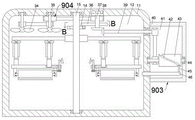
the invention relates to a device for removing surface burrs of a screw-shaped cast workpiece, which comprises a portal frame 11, wherein a transmission cavity 12 which is through from left to right is arranged in the portal frame 11, a central shaft 15 is connected in the transmission cavity 12 in a rotating manner, a cross rotating rod 13 is arranged on the central shaft 15, lifting grabbing devices 901 are arranged on the lower sides of four branches of the cross rotating rod 13, each grabbing device 901 comprises two electric lifting rods 16 which are connected with the lower side of a single branch of the cross rotating rod 13 in a rotating manner and distributed along the cross rotating rod 13, a connecting rod 17 is fixedly arranged at the lower end of each electric lifting rod 16, a bearing table 18 is fixedly arranged at the lower end of the connecting rod 17 far away from the central shaft 15 side, a sliding cavity 27 is arranged on the bearing table 18, an anti-falling block 26 fixedly connected with the connecting rod 17 near the central shaft 15 side is connected in the sliding cavity 27 in a sliding manner, a sliding rod 24 is, the lower side of the bearing table 18 is provided with symmetrical hanging rods 20 which are positioned on the front side and the rear side of the sliding rod 24, the hanging rods 20 are connected with a rotating arm 19 in a rotating mode, a triangular block 21 is arranged on the rotating arm 19, the electric lifting rod 16 extends and retracts to adjust the height of the bearing table 18 through the connecting rod 17, the rotating arm 19 rotates to grab a casting screw-shaped plane through the triangular block 21 and grab a workpiece, material boxes 22 which are positioned on the left side and the right side of the central shaft 15 and are symmetrical are arranged on the lower side of the transmission cavity 12, a switch device 902 which enables the rotating arm 19 to rotate is arranged in each material box 22, a dust cover 40 is fixedly arranged on the front side of the portal frame 11, a friction device 903 for removing burrs is arranged on each dust cover 40, each friction device 903 comprises a linking cavity 41 positioned in each dust cover 40, and the inner wall on the rear side of each, a shifting lever 45 is arranged on the upper side of the right end of the friction plate 46, a driven shaft 44 is rotatably connected in the connecting cavity 41, a rotating barrel 43 is arranged on the driven shaft 44, a wave groove 42 which is in sliding connection with the shifting lever 45 is arranged on the rotating barrel 43, the shifting lever 45 is limited by the inner wall of the wave groove 42 when the rotating barrel 43 rotates, so that the friction plate 46 is pushed to slide to the transmission cavity 12 to polish workpieces, and a soot blower 904 is arranged on the inner wall of the top end of the transmission cavity 12.
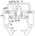
According to an embodiment, the following detailed description is provided for the grasping apparatus 901, the grasping apparatus 901 further includes a fixing pin 28 fixedly connected to the rotating arm 19, a synchronization plate 30 is fixedly disposed at a lower end of the sliding rod 24, a resistance spring 25 is connected between the synchronization plate 30 and a lower side of the bearing platform 18, a through groove 29 slidably connected to the fixing pin 28 and symmetrical in front and rear is disposed on the synchronization plate 30, a bevel block 23 is fixedly disposed at an upper end of the sliding rod 24, the sliding rod 24 drives the synchronization plate 30 to synchronously lift and lower, and the fixing pin 28 is limited by an inner wall of the through groove 29, so that the rotating arm 19 is rotated, and a plane portion of a spiral workpiece is hooked by the triangular block 21, thereby facilitating grasping.
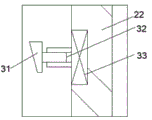
According to an embodiment, the switch device 902 is described in detail below, where the switch device 902 includes a hydraulic machine 33 embedded in an inner wall of the material tank 22 on a side close to the central shaft 15, a hydraulic rod 32 is dynamically connected to a side of the hydraulic machine 33 away from the central shaft 15, an inclined push block 31 slidably connected to the inclined block 23 is fixed to the hydraulic rod 32, and the hydraulic machine 33 is started to push the inclined push block 31 to move away from the central shaft 15 through the hydraulic rod 32.
According to an embodiment, the friction device 903 is described in detail below, the friction device 903 further comprises a transmission shaft 39 rotatably connected with the inner wall of the rear side of the engaging cavity 41 and extending into the transmission cavity 12, and the transmission shaft 39 is in belt transmission connection with the engaging cavity 41.
According to an embodiment, the soot blower 904 is described in detail below, the soot blower 904 includes two fixed shafts 35 rotatably connected to an upper inner wall of the transmission cavity 12 and located behind the central shaft 15, the fixed shafts 35 are in belt transmission connection, a fan 34 is fixedly disposed at a lower end of the fixed shafts 35, a motor 38 is embedded in an inner wall of a top end of the transmission cavity 12 and located in front of the central shaft 15, a driving shaft 37 connected to a bevel gear pair of the driving shaft 39 is dynamically connected to a lower end of the motor 38, the driving shaft 37 is in belt transmission connection with the fixed shaft 35 near the central shaft 15, a dial wheel 36 is disposed on the driving shaft 37, a sheave 14 abutting against the dial wheel 36 is disposed on the central shaft 15, the motor 38 starts to rotate the driving shaft 37, the driving shaft 37 on one hand drives the driving shaft 39 to rotate through the bevel gear pair, on the other hand, the fixed shaft 35 is rotated through belt transmission, so that the fan 34 blows air downwards to remove dust, and simultaneously, the dial wheel 36 rotates once through the contact of the dial wheel 36 and the grooved wheel 14, and the grooved wheel 14 rotates ninety degrees.
The use steps of the device for removing surface burrs of a screw-shaped cast workpiece will be described in detail with reference to fig. 1 to 5:
at the beginning, the electric lifting rod 16 contracts, the rotating arm 19 is positioned at the upper side of the material box 22, the hydraulic rod 32 contracts, the friction plate 46 is positioned in the connecting cavity 41, and the side surface of the longest end of the triangular block 21 is horizontally arranged.
The motor 38 starts the rotating driving shaft 37, the driving shaft 37 drives the transmission shaft 39 to rotate through a bevel gear pair on one hand, and the fixed shaft 35 rotates through belt transmission on the other hand, so that the fan 34 blows air downwards to remove dust, the branches of the cross rotating rod 13 on the rearmost side are cleaned, meanwhile, the dial wheel 36 rotates for one circle through the contact of the dial wheel 36 and the grooved wheel 14, the grooved wheel 14 rotates ninety degrees, and further the cross rotating rod 13 is driven to rotate ninety degrees through the central shaft 15;
the cross rotating rod 13 stays for a period of time after rotating each time, when the leftmost cross rotating rod 13 works, the electric lifting rod 16 extends and lowers down the bearing platform 18, the rotating arm 19 is positioned in the material box 22, then the hydraulic machine 33 is started to push the inclined push block 31 to move towards the side far away from the central shaft 15 through the hydraulic rod 32, further the inclined block 23 moves downwards through the inclined plane sliding with the inclined push block 31, so that the sliding rod 24 drives the synchronous plate 30 to move downwards and stretch the resistance spring 25 synchronously, the fixed pin 28 is limited through the inner wall of the through groove 29, the rotating arm 19 is rotated to be opened, then the hydraulic machine 33 is started to shrink the hydraulic rod 32, the synchronous plate 30 moves upwards under the elastic force restoring of the resistance spring 25, the work is repeated in the opposite direction, the plane part hooking the spiral workpiece is grabbed through the triangular block 21, then the electric lifting rod 16 close to the central shaft 15 side is firstly shrunk, and the length change is compensated through the sliding of the anti-falling block, the bearing table 18 is inclined, the workpiece which is not clamped by the hanging rod 20 is poured out, and then the central shaft 15 is synchronously started to contract and recover to the initial state;
the working steps of the branches of the cross rotating rod 13 on the left side and the right side are the same, the branches of the cross rotating rod 13 on the front side are triangular blocks 21 which restore to the initial position after grabbing a workpiece, the driving shaft 39 drives the driven shaft 44 to rotate through belt driving, the driven shaft 44 rotates to pass through the rotating barrel 43, the rotating barrel 43 rotates to limit the deflector rod 45 due to the inner wall of the wave groove 42, and therefore the friction plate 46 is pushed to slide to the transmission cavity 12 to grind the workpiece to remove burrs.
The invention has the beneficial effects that: according to the invention, the disc type stations are sequentially exchanged to realize a mechanical batch polishing process, workpieces are fished in a double-sided rotating clamping mode, a vertical angle is formed at one side of the workpieces for fixing, so that a large number of workpieces are grabbed and the orientations of the workpieces are calibrated, intermittent rotating motion of a grabbing part is realized through a sheave structure, processes of polishing, placing and cleaning are sequentially realized, the manual polishing integrity is combined, and the standardization of deburring degree is also ensured.
In the above manner, a person skilled in the art can make various changes depending on the operation mode within the scope of the present invention.
Claims (5)
1. The utility model provides a surperficial burr remove device of cast workpiece of screw form, includes the portal frame, be equipped with the transmission chamber that link up about controlling in the portal frame, the transmission intracavity rotates and is connected with center pin, its characterized in that: a cross rotating rod is arranged on the central shaft;
the lower sides of four branches of the cross-shaped rotating rod are respectively provided with a lifting gripping device, the gripping devices comprise two electric lifting rods which are rotatably connected with the lower sides of single branches of the cross-shaped rotating rod and are distributed along the cross-shaped rotating rod, the lower end of the electric lifting rod is fixedly provided with a connecting rod, the lower end of the connecting rod far away from the central shaft is fixedly provided with a bearing platform, a slide cavity is arranged on the bearing table, an anti-falling block fixedly connected with the connecting rod close to the central shaft side is connected in the slide cavity in a sliding way, the side of the bearing platform close to the central shaft is connected with a slide bar in a sliding way, the lower side of the bearing platform is provided with symmetrical hanging rods which are positioned at the front side and the rear side of the slide bar, a rotating arm is rotatably connected to the hanging rod, a triangular block is arranged on the rotating arm, the height of the bearing table is adjusted by the electric lifting rod through the connecting rod in a telescopic mode, and a workpiece is grabbed by the rotating arm through the triangular block in a rotating mode;
the lower side of the transmission cavity is provided with symmetrical material tanks which are positioned at the left side and the right side of the central shaft, a switch device which enables the rotating arm to rotate is arranged in each material tank, the front side of the portal frame is fixedly provided with a dust cover, and the dust cover is provided with a friction device for removing burrs;
the friction device comprises a linking cavity positioned in the dust cover, the inner wall of the rear side of the linking cavity is connected with a friction plate extending into the transmission cavity in a sliding mode, a driving lever is arranged on the upper side of the right end of the friction plate, a driven shaft is connected in the linking cavity in a rotating mode, a rotating barrel is arranged on the driven shaft, a wave groove in sliding connection with the driving lever is formed in the rotating barrel, the rotating barrel rotates, the driving lever is limited by the inner wall of the wave groove, therefore, the friction plate is pushed to slide to a polishing workpiece in the transmission cavity, and a soot blowing device is arranged on the inner wall of the top.
2. A surface burr removing device of a screw-like cast workpiece according to claim 1, wherein: grabbing device still include with rocking arm fixed connection's fixed pin, the fixed synchronous board that is equipped with of slide bar lower extreme, synchronous board with be connected with the resistance spring between the plummer downside, synchronous board be equipped with fixed pin sliding connection and front and back symmetry lead to the groove, the fixed bevel piece that is equipped with in slide bar upper end.
3. A surface burr removing device of a screw-like cast workpiece according to claim 2, wherein: the switch device comprises a hydraulic machine embedded on the inner wall of the material box close to the side of the central shaft, the side of the hydraulic machine far away from the central shaft is in power connection with a hydraulic rod, and an inclined push block in sliding connection with the inclined block is fixedly arranged on the hydraulic rod.
4. A surface burr removing device of a screw-like cast workpiece according to claim 1, wherein: friction device still include with link up the chamber rear side inner wall and rotate the connection and extend to the transmission shaft in the transmission chamber, the transmission shaft with link up the area transmission connection between the chamber.
5. A screw-like cast workpiece surface burr removing device as recited in claim 4, wherein: the soot blower include with transmission chamber upside inner wall rotates to be connected and is located two fixed axles of center pin rear side, the belt drive is connected between the fixed axle, the fixed fan that is equipped with of fixed axle lower extreme, transmission chamber top inner wall is embedded to have and is located the motor of center pin front side, motor lower extreme power connection have with the drive shaft that transmission shaft bevel gear pair is connected, the drive shaft with be close to the center shaft side the belt drive is connected between the fixed axle, be equipped with the thumb wheel in the drive shaft, be equipped with on the center pin with the sheave of thumb wheel butt.
Priority Applications (1)
| Application Number | Priority Date | Filing Date | Title |
|---|---|---|---|
| CN202010100533.2A CN111098199B (en) | 2020-02-19 | 2020-02-19 | Surface burr removing device for screw-shaped casting workpiece |
Applications Claiming Priority (1)
| Application Number | Priority Date | Filing Date | Title |
|---|---|---|---|
| CN202010100533.2A CN111098199B (en) | 2020-02-19 | 2020-02-19 | Surface burr removing device for screw-shaped casting workpiece |
Publications (2)
| Publication Number | Publication Date |
|---|---|
| CN111098199A CN111098199A (en) | 2020-05-05 |
| CN111098199B true CN111098199B (en) | 2021-02-26 |
Family
ID=70428118
Family Applications (1)
| Application Number | Title | Priority Date | Filing Date |
|---|---|---|---|
| CN202010100533.2A Active CN111098199B (en) | 2020-02-19 | 2020-02-19 | Surface burr removing device for screw-shaped casting workpiece |
Country Status (1)
| Country | Link |
|---|---|
| CN (1) | CN111098199B (en) |
Families Citing this family (1)
| Publication number | Priority date | Publication date | Assignee | Title |
|---|---|---|---|---|
| CN113237819B (en) * | 2021-05-12 | 2024-03-22 | 亚能生物技术(深圳)有限公司 | Flow cytometry |
Family Cites Families (4)
| Publication number | Priority date | Publication date | Assignee | Title |
|---|---|---|---|---|
| DE4125654A1 (en) * | 1991-08-02 | 1993-02-04 | Siepmann & Co Gmbh & Co E | POT GRINDING MACHINE, ESPECIALLY FOR GRINDING SCISSOR PARTS |
| CN203401370U (en) * | 2013-07-23 | 2014-01-22 | 安徽力成机械装备有限公司 | Numerical control full-automatic holder window grinder |
| CN207344377U (en) * | 2017-08-31 | 2018-05-11 | 东风精密铸造安徽有限公司 | A kind of casting clamping device |
| CN110695803A (en) * | 2019-08-27 | 2020-01-17 | 安徽恒乐家庭用品有限公司 | Edging device is used in glass cup processing |
-
2020
- 2020-02-19 CN CN202010100533.2A patent/CN111098199B/en active Active
Also Published As
| Publication number | Publication date |
|---|---|
| CN111098199A (en) | 2020-05-05 |
Similar Documents
| Publication | Publication Date | Title |
|---|---|---|
| CN214054802U (en) | Foundry goods ash removal device that polishes | |
| CN213166028U (en) | Blank trimming device for ceramic processing | |
| CN111098199B (en) | Surface burr removing device for screw-shaped casting workpiece | |
| CN111957933A (en) | Processing device and processing method for film-coated sand casting sand box | |
| CN210173589U (en) | Clamping device of four-axis robot arm | |
| CN112405137B (en) | Surface burr removing device for mechanical parts | |
| CN116533118B (en) | Intelligent polishing equipment for large casting robot | |
| CN112795741A (en) | Steel quenching and hardening device for intelligent manufacturing | |
| CN109158997B (en) | Grinding equipment for surface of pig iron casting | |
| CN219293489U (en) | Compression spring end face grinding device | |
| CN110842686A (en) | Cylindrical casting surface polishing device | |
| CN217168233U (en) | Irregular casting clamping device for casting production | |
| CN113635189B (en) | Machining process for surface polishing and grinding system of forging and casting | |
| CN214979843U (en) | Automobile die casting surface deburring cleaning equipment | |
| CN210938637U (en) | Automobile spare and accessory part mechanical product rust cleaning processingequipment | |
| CN112605755A (en) | Quick grinding device of plane joint line on foundry goods | |
| CN208050921U (en) | A kind of casting grinding device | |
| CN111730479A (en) | Polymorphic metal polisher device of duplex position continuous cutting | |
| CN108687589B (en) | Bearing end surface polishing device | |
| CN113059412A (en) | Machining system for automobile hub and machining process of machining system | |
| CN112548019A (en) | Forging machine capable of realizing multidirectional hammering | |
| CN112589634A (en) | Automatic running gear and steel sheet surface rust cleaning device | |
| CN214922859U (en) | Foundry goods grinding device for fire control accessories | |
| CN217572206U (en) | Grinding device is used in metal casting production | |
| CN211890314U (en) | Square tube polishing and grinding device |
Legal Events
| Date | Code | Title | Description |
|---|---|---|---|
| PB01 | Publication | ||
| PB01 | Publication | ||
| SE01 | Entry into force of request for substantive examination | ||
| SE01 | Entry into force of request for substantive examination | ||
| TA01 | Transfer of patent application right | ||
| TA01 | Transfer of patent application right |
Effective date of registration: 20210126 Address after: 325000 Building 1, No. 70, Huancheng Road, Haicheng street, Wenzhou Economic and Technological Development Zone, Wenzhou City, Zhejiang Province Applicant after: Wenzhou weiertai Standard Parts Co.,Ltd. Address before: 325024 e-commerce building, 180 Wenchang Road, Puzhou street, Longwan District, Wenzhou City, Zhejiang Province Applicant before: Wenzhou Tianhe Technology Co.,Ltd. |
|
| GR01 | Patent grant | ||
| GR01 | Patent grant |