CN111096004B - Method and device for synchronous signal scanning based on synchronous grid - Google Patents
Method and device for synchronous signal scanning based on synchronous grid Download PDFInfo
- Publication number
- CN111096004B CN111096004B CN201880057885.5A CN201880057885A CN111096004B CN 111096004 B CN111096004 B CN 111096004B CN 201880057885 A CN201880057885 A CN 201880057885A CN 111096004 B CN111096004 B CN 111096004B
- Authority
- CN
- China
- Prior art keywords
- frequency locations
- frequency
- locations
- synchronization
- synchronization signal
- Prior art date
- Legal status (The legal status is an assumption and is not a legal conclusion. Google has not performed a legal analysis and makes no representation as to the accuracy of the status listed.)
- Active
Links
Images


Classifications
-
- H—ELECTRICITY
- H04—ELECTRIC COMMUNICATION TECHNIQUE
- H04J—MULTIPLEX COMMUNICATION
- H04J11/00—Orthogonal multiplex systems, e.g. using WALSH codes
- H04J11/0069—Cell search, i.e. determining cell identity [cell-ID]
- H04J11/0073—Acquisition of primary synchronisation channel, e.g. detection of cell-ID within cell-ID group
-
- H—ELECTRICITY
- H04—ELECTRIC COMMUNICATION TECHNIQUE
- H04B—TRANSMISSION
- H04B7/00—Radio transmission systems, i.e. using radiation field
- H04B7/24—Radio transmission systems, i.e. using radiation field for communication between two or more posts
- H04B7/26—Radio transmission systems, i.e. using radiation field for communication between two or more posts at least one of which is mobile
- H04B7/2643—Radio transmission systems, i.e. using radiation field for communication between two or more posts at least one of which is mobile using time-division multiple access [TDMA]
- H04B7/2656—Radio transmission systems, i.e. using radiation field for communication between two or more posts at least one of which is mobile using time-division multiple access [TDMA] for structure of frame, burst
-
- H—ELECTRICITY
- H04—ELECTRIC COMMUNICATION TECHNIQUE
- H04J—MULTIPLEX COMMUNICATION
- H04J11/00—Orthogonal multiplex systems, e.g. using WALSH codes
- H04J11/0069—Cell search, i.e. determining cell identity [cell-ID]
- H04J11/0076—Acquisition of secondary synchronisation channel, e.g. detection of cell-ID group
-
- H—ELECTRICITY
- H04—ELECTRIC COMMUNICATION TECHNIQUE
- H04W—WIRELESS COMMUNICATION NETWORKS
- H04W56/00—Synchronisation arrangements
- H04W56/001—Synchronization between nodes
-
- H—ELECTRICITY
- H04—ELECTRIC COMMUNICATION TECHNIQUE
- H04W—WIRELESS COMMUNICATION NETWORKS
- H04W56/00—Synchronisation arrangements
- H04W56/001—Synchronization between nodes
- H04W56/0025—Synchronization between nodes synchronizing potentially movable access points
-
- H—ELECTRICITY
- H04—ELECTRIC COMMUNICATION TECHNIQUE
- H04W—WIRELESS COMMUNICATION NETWORKS
- H04W56/00—Synchronisation arrangements
- H04W56/0035—Synchronisation arrangements detecting errors in frequency or phase
-
- H—ELECTRICITY
- H04—ELECTRIC COMMUNICATION TECHNIQUE
- H04W—WIRELESS COMMUNICATION NETWORKS
- H04W72/00—Local resource management
- H04W72/04—Wireless resource allocation
- H04W72/044—Wireless resource allocation based on the type of the allocated resource
- H04W72/0453—Resources in frequency domain, e.g. a carrier in FDMA
Abstract
Certain aspects of the present disclosure generally relate to wireless communications. In some aspects, a user equipment may identify that a frequency band is associated with a first digital scheme and a second digital scheme for synchronization, and/or perform a synchronization scan using stored data to detect a synchronization signal block, wherein the stored data comprises data for a plurality of frequency positions of the frequency band, and wherein the synchronization scan is performed with respect to a first set of frequency positions of the plurality of frequency positions associated with the first digital scheme, and wherein the synchronization scan is performed with respect to a second set of frequency positions of the plurality of frequency positions associated with the second digital scheme, wherein the second set of frequency positions comprises an appropriate subset of frequency positions of the plurality of frequency positions. Numerous other aspects are provided.
Description
35 U.S.C. § 119 based cross-reference to related applications
The present application claims priority from: U.S. provisional patent application No.62/556,077 entitled "techiniques AND APPARATUSES FOR SYNCHRONIZATION SIGNAL SCANNING base AT LEAST IN PART ON a SYNCHRONIZATION system", filed ON 8.9.2017; AND U.S. non-provisional patent application No.16/123,784 entitled "techiniques AND APPARATUSES FOR SYNCHRONIZATION SIGNAL SCANNING base AT LEAST IN PART ON a SYNCHRONIZATION system," filed ON 6.9.2018, both of which are hereby expressly incorporated by reference.
Technical Field
Aspects of the present disclosure relate generally to wireless communications, and more specifically to techniques and apparatuses for synchronization signal scanning based at least in part on a synchronization grid.
Background
Wireless communication systems are widely deployed to provide various telecommunication services such as telephony, video, data, messaging, and broadcasting. A typical wireless communication system may employ multiple-access techniques capable of supporting communication with multiple users by sharing the available system resources (e.g., bandwidth, transmit power, etc.). Examples of such multiple-access techniques include Code Division Multiple Access (CDMA) systems, Time Division Multiple Access (TDMA) systems, Frequency Division Multiple Access (FDMA) systems, Orthogonal Frequency Division Multiple Access (OFDMA) systems, single carrier frequency division multiple access (SC-FDMA) systems, time division synchronous code division multiple access (TD-SCDMA) systems, and Long Term Evolution (LTE). LTE/LTE-advanced is an enhanced set of Universal Mobile Telecommunications System (UMTS) mobile standards promulgated by the third generation partnership project (3 GPP).
A wireless communication network may include a plurality of Base Stations (BSs) capable of supporting communication for a plurality of User Equipments (UEs). A User Equipment (UE) may communicate with a Base Station (BS) via a downlink and an uplink. The downlink (or forward link) refers to the communication link from the BS to the UE, and the uplink (or reverse link) refers to the communication link from the UE to the BS. As will be described in greater detail herein, the BS may be referred to as a node B, gNB, an Access Point (AP), a radio head, a Transmit Receive Point (TRP), a New Radio (NR) BS, a 5G node B, etc.
The above multiple access techniques have been employed in various telecommunications standards to provide a common protocol that enables different user equipment to communicate on a city, country, region, and even global level. New Radios (NR), which may also be referred to as 5G, are an enhanced set of LTE mobile standards promulgated by the third generation partnership project (3 GPP). NR is designed to better integrate with other open standards by improving spectral efficiency, reducing costs, improving services, utilizing new spectrum, and using Orthogonal Frequency Division Multiplexing (OFDM) with Cyclic Prefix (CP) (CP-OFDM) on the Downlink (DL), CP-OFDM and/or SC-FDM (e.g., also known as discrete fourier transform spread OFDM (DFT-s-OFDM)) on the Uplink (UL), to better support mobile broadband internet access, and to support beamforming, multiple-input multiple-output (MIMO) antenna techniques, and carrier aggregation. However, as the demand for mobile broadband access continues to grow, there is a need for further improvements in LTE and NR technology. Preferably, these improvements should be applicable to other multiple access techniques and telecommunications standards employing these techniques.
Disclosure of Invention
In some aspects, a method for wireless communication performed by a user equipment may comprise: identifying that a frequency band is associated with a first numerology and a second numerology for synchronization; and performing a synchronization scan using the stored data to detect a synchronization signal block, wherein the stored data comprises data for a plurality of frequency locations of the frequency band, wherein the synchronization scan is performed with respect to a first set of frequency locations of the plurality of frequency locations associated with the first digital scheme, and wherein the synchronization scan is performed with respect to a second set of frequency locations of the plurality of frequency locations associated with the second digital scheme, wherein the second set of frequency locations comprises an appropriate subset of the plurality of frequency locations.
In some aspects, a user equipment for wireless communication may include a memory and one or more processors operatively coupled to the memory. The memory and the one or more processors may be configured to: identifying that a frequency band is associated with a first numerology and a second numerology for synchronization; and performing a synchronization scan using the stored data to detect a synchronization signal block, wherein the stored data comprises data for a plurality of frequency locations of the frequency band, wherein the synchronization scan is performed with respect to a first set of frequency locations of the plurality of frequency locations associated with the first digital scheme, and wherein the synchronization scan is performed with respect to a second set of frequency locations of the plurality of frequency locations associated with the second digital scheme, wherein the second set of frequency locations comprises an appropriate subset of the plurality of frequency locations.
In some aspects, a non-transitory computer-readable medium may store one or more instructions for wireless communication. The one or more instructions, when executed by one or more processors of a user device, may cause the one or more processors to: identifying that a frequency band is associated with a first numerology and a second numerology for synchronization; and performing a synchronization scan using the stored data to detect a synchronization signal block, wherein the stored data comprises data for a plurality of frequency locations of the frequency band, wherein the synchronization scan is performed with respect to a first set of frequency locations of the plurality of frequency locations associated with the first digital scheme, and wherein the synchronization scan is performed with respect to a second set of frequency locations of the plurality of frequency locations associated with the second digital scheme, wherein the second set of frequency locations comprises an appropriate subset of the plurality of frequency locations.
In some aspects, an apparatus for wireless communication may comprise: means for identifying that a frequency band is associated with a first numerology and a second numerology for synchronization; and means for performing a synchronization scan using the stored data to detect a synchronization signal block, wherein the stored data comprises data for a plurality of frequency locations of the frequency band, wherein the synchronization scan is performed with respect to a first set of frequency locations of the plurality of frequency locations associated with the first digital scheme, and wherein the synchronization scan is performed with respect to a second set of frequency locations of the plurality of frequency locations associated with the second digital scheme, wherein the second set of frequency locations comprises an appropriate subset of the plurality of frequency locations.
Aspects include, in general, methods, apparatuses, systems, computer program products, non-transitory computer-readable media, user equipment, wireless communication devices, and processing systems substantially as described herein with reference to and as illustrated by the accompanying drawings and description.
The foregoing has outlined rather broadly the features and technical advantages of examples according to the present disclosure in order that the detailed description that follows may be better understood. Additional features and advantages will be described hereinafter. The conception and specific examples disclosed may be readily utilized as a basis for modifying or designing other structures for carrying out the same purposes of the present disclosure. Such equivalent constructions do not depart from the scope of the appended claims. The nature of the concepts disclosed herein (both their organization and method of operation), together with the advantages associated therewith, will be better understood from the following description when considered in connection with the accompanying figures. Each of the figures is provided for the purposes of illustration and description and is not intended as a definition of the limits of the claims.
Drawings
So that the manner in which the above recited features of the present disclosure can be understood in detail, a more particular description of the invention, briefly summarized above, may be had by reference to aspects, some of which are illustrated in the appended drawings. It is to be noted, however, that the appended drawings illustrate only certain typical aspects of this disclosure and are therefore not to be considered limiting of its scope, for the description may admit to other equally effective aspects. The same reference numbers in different drawings may identify the same or similar elements.
Fig. 1 is a block diagram conceptually illustrating an example of a wireless communication network in accordance with various aspects of the present disclosure.
Fig. 2 is a block diagram conceptually illustrating an example of a base station in a wireless communication network communicating with a User Equipment (UE), in accordance with various aspects of the present disclosure.
Fig. 3A is a block diagram conceptually illustrating an example of a frame structure in a wireless communication network, in accordance with various aspects of the present disclosure.
Fig. 3B is a block diagram conceptually illustrating an example synchronous communication hierarchy in a wireless communication network, in accordance with various aspects of the present disclosure.
Fig. 4 is a block diagram conceptually illustrating an example slot format with a normal cyclic prefix, in accordance with various aspects of the present disclosure.
Fig. 5 is a diagram illustrating an example of performing a synchronization scan based at least in part on a synchronization signal location table identifying a single digital scheme for each frequency location in accordance with various aspects of the present disclosure.
Fig. 6 is a diagram illustrating an example process performed, for example, by a user device, in accordance with various aspects of the present disclosure.
Detailed Description
Various aspects of the disclosure are described more fully below with reference to the accompanying drawings. This disclosure may, however, be embodied in many different forms and should not be construed as limited to any specific structure or function presented throughout this disclosure. Rather, these aspects are provided so that this disclosure will be thorough and complete, and will fully convey the scope of the disclosure to those skilled in the art. Based on the teachings herein one skilled in the art should appreciate that the scope of the present disclosure is intended to cover any aspect of the present disclosure disclosed herein, whether implemented independently of or in combination with any other aspect of the present disclosure. For example, an apparatus may be implemented or a method may be practiced using any number of the aspects set forth herein. Moreover, the scope of the present disclosure is intended to cover such an apparatus or method implemented with other structure, functionality, or structure and functionality in addition to or other than the various aspects of the present disclosure set forth herein. It should be understood that any aspect of the present disclosure disclosed herein may be embodied by one or more elements of a claim.
Several aspects of a telecommunications system will now be presented with reference to various apparatus and techniques. These apparatus and techniques are described in the following detailed description and illustrated in the accompanying drawings by various blocks, modules, components, circuits, steps, procedures, algorithms, etc. (collectively referred to as "elements"). These elements may be implemented using hardware, software, or a combination thereof. Whether such elements are implemented as hardware or software depends upon the particular application and design constraints imposed on the overall system.
It is noted that although aspects may be described herein using terms commonly associated with 3G and/or 4G wireless technologies, aspects of the present disclosure may be applied in other generation-based communication systems, such as 5G and beyond (including NR technologies).
Fig. 1 is a diagram illustrating a network 100 in which aspects of the present disclosure may be implemented. The network 100 may be an LTE network or some other wireless network (e.g., a 5G or NR network). Wireless network 100 may include a plurality of BSs 110 (shown as BS 110a, BS 110b, BS 110c, and BS 110d) and other network entities. A BS is an entity that communicates with User Equipment (UE) and may also be referred to as a base station, NR BS, node B, gNB, 5G node b (nb), access point, Transmission Reception Point (TRP), etc. Each BS may provide communication coverage for a particular geographic area. In 3GPP, the term "cell" can refer to a coverage area of a BS and/or a BS subsystem serving that coverage area, depending on the context in which the term is used.
The BS may provide communication coverage for a macrocell, a picocell, a femtocell, and/or another type of cell. A macro cell may cover a relatively large geographic area (e.g., several kilometers in radius) and may allow unrestricted access by UEs with service subscriptions. A pico cell may cover a relatively small geographic area and may allow unrestricted access by UEs with service subscriptions. A femto cell may cover a relatively small geographic area (e.g., a residence) and may allow restricted access by UEs having an association with the femto cell (e.g., UEs in a Closed Subscriber Group (CSG)). The BS for the macro cell may be referred to as a macro BS. The BS for the pico cell may be referred to as a pico BS. The BS for the femto cell may be referred to as a femto BS or a home BS. In the example shown in fig. 1, BS 110a may be a macro BS for macro cell 102a, BS 110b may be a pico BS for pico cell 102b, and BS 110c may be a femto BS for femto cell 102 c. A BS may support one or more (e.g., three) cells. The terms "eNB", "base station", "NR BS", "gNB", "TRP", "AP", "node B", "5G NB" and "cell" may be used interchangeably herein.
In some examples, the cell may not necessarily be stationary, and the geographic area of the cell may move according to the location of the mobile BS. In some examples, BSs may be interconnected to each other and/or to one or more other BSs or network nodes (not shown) in the access network 100 by various types of backhaul interfaces (e.g., direct physical connections, virtual networks, and/or the like using any suitable transport network).
The wireless network 100 may be a heterogeneous network including different types of BSs (e.g., macro BSs, pico BSs, femto BSs, relay BSs, etc.). These different types of BSs may have different transmit power levels, different coverage areas, and different effects on interference in wireless network 100. For example, the macro BS may have a high transmit power level (e.g., 5 to 40 watts), while the pico BS, femto BS, and relay BS may have a lower transmit power level (e.g., 0.1 to 2 watts).
UEs 120 (e.g., 120a, 120b, 120c) may be dispersed throughout wireless network 100, and each UE may be stationary or mobile. A UE may also be called an access terminal, mobile station, subscriber unit, station, etc. The UE may be a cellular telephone (e.g., a smartphone), a Personal Digital Assistant (PDA), a wireless modem, a wireless communication device, a handheld device, a laptop computer, a cordless telephone, a Wireless Local Loop (WLL) station, a tablet device, a camera, a gaming device, netbooks, smartbooks, ultrabooks, medical devices or appliances, biometric sensors/devices, wearable devices (smartwatches, smartclothing, smart glasses, smart wristbands, smart jewelry (e.g., smart rings, smart bracelets, etc.)), entertainment devices (e.g., music or video devices, or satellite radio units, etc.), vehicle components or sensors, smart meters/sensors, industrial manufacturing devices, global positioning system devices, or any other suitable device configured to communicate via a wireless or wired medium.
Some UEs may be considered Machine Type Communication (MTC) or evolved or enhanced machine type communication (eMTC) UEs. MTC and eMTC UEs include, for example, a robot, a drone, a remote device (such as a sensor, a meter, a monitor, a location tag, etc.), which may communicate with a base station, another device (e.g., a remote device), or some other entity. The wireless node may provide a connection to or to a network (e.g., a wide area network such as the internet or a cellular network), for example, via a wired or wireless communication link. Some UEs may be considered internet of things (IoT) devices and/or may be implemented as NB-IoT (narrowband internet of things) devices. Some UEs may be considered Customer Premises Equipment (CPE). UE120 may be included inside a housing that houses components of UE120, such as a processor component, a memory component, and the like.
In general, any number of wireless networks may be deployed in a given geographic area. Each wireless network may support a particular RAT and may operate on one or more frequencies. A RAT may also be referred to as a radio technology, air interface, etc. Frequencies may also be referred to as carriers, channels, etc. Each frequency may support a single RAT in a given geographic area in order to avoid interference between wireless networks of different RATs. In some cases, NR or 5G RAT networks may be deployed.
In some examples, access to an air interface may be scheduled, where a scheduling entity (e.g., a base station) allocates resources for communication between some or all of the devices and apparatuses within a service area or cell of the scheduling entity. Within this disclosure, the scheduling entity may be responsible for scheduling, assigning, reconfiguring, and releasing resources for one or more subordinate entities, as discussed further below. That is, for scheduled communications, the subordinate entity utilizes the resources allocated by the scheduling entity.
The base station is not the only entity that can be used as a scheduling entity. That is, in some examples, a UE may serve as a scheduling entity that schedules resources for one or more subordinate entities (e.g., one or more other UEs). In this example, the UE is acting as a scheduling entity, while other UEs utilize the resources scheduled by the UE for wireless communication. The UE may serve as a scheduling entity in a peer-to-peer (P2P) network and/or in a mesh network. In the mesh network example, in addition to communicating with the scheduling entity, the UEs may optionally communicate directly with each other.
Thus, in a wireless communication network having scheduled access to time-frequency resources and having a cellular configuration, a P2P configuration, and a mesh configuration, a scheduling entity and one or more subordinate entities may communicate utilizing the scheduled resources.
As noted above, fig. 1 is provided by way of example only. Other examples are possible and may differ from the example described with respect to fig. 1.
Fig. 2 shows a block diagram of a design of BS 110 and UE120 (which may be one of the base stations and one of the UEs in fig. 1). BS 110 may be equipped with T antennas 234a through 234T and UE120 may be equipped with R antennas 252a through 252R, where T ≧ 1 and R ≧ 1 in general.
At BS 110, transmit processor 220 may receive data for one or more UEs from a data source 212, select one or more Modulation and Coding Schemes (MCSs) for each UE based at least in part on a Channel Quality Indicator (CQI) received from the UE, process (e.g., encode and modulate) the data for each UE based at least in part on the MCS selected for the UE, and provide data symbols for all UEs. Transmit processor 220 may also process system information (e.g., for semi-Static Resource Partitioning Information (SRPI), etc.) and control information (e.g., CQI requests, grants, upper layer signaling, etc.), as well as provide overhead symbols and control symbols. Transmit processor 220 may also generate reference symbols for reference signals (e.g., cell-specific reference signals (CRS)) and synchronization signals (e.g., Primary Synchronization Signals (PSS) and Secondary Synchronization Signals (SSS)). A Transmit (TX) multiple-input multiple-output (MIMO) processor 230 may perform spatial processing (e.g., precoding) on the data symbols, the control symbols, the overhead symbols, and/or the reference symbols, if applicable, and may provide T output symbol streams to T Modulators (MODs) 232a through 232T. Each modulator 232 may process a respective output symbol stream (e.g., for OFDM, etc.) to obtain an output sample stream. Each modulator 232 may further process (e.g., convert to analog, amplify, filter, and upconvert) the output sample stream to obtain a downlink signal. T downlink signals from modulators 232a through 232T may be transmitted via T antennas 234a through 234T, respectively. According to certain aspects described in more detail below, a synchronization signal may be generated using position coding to convey additional information.
At UE120, antennas 252a through 252r may receive downlink signals from BS 110 and/or other base stations and may provide received signals to demodulators (DEMODs) 254a through 254r, respectively. Each demodulator 254 may condition (e.g., filter, amplify, downconvert, and digitize) a received signal to obtain input samples. Each demodulator 254 may further process the input samples (e.g., for OFDM, etc.) to obtain received symbols. A MIMO detector 256 may obtain received symbols from all R demodulators 254a through 254R, perform MIMO detection on the received symbols (if applicable), and provide detected symbols. A receive processor 258 may process (e.g., demodulate and decode) the detected symbols, provide decoded data for UE120 to a data sink 260, and provide decoded control information and system information to a controller/processor 280. The channel processor may determine Reference Signal Received Power (RSRP), Received Signal Strength Indicator (RSSI), Reference Signal Received Quality (RSRQ), Channel Quality Indicator (CQI), and the like.
On the uplink, at UE120, a transmit processor 264 may receive and process data from a data source 262 and control information from a controller/processor 280 (e.g., for reporting including RSRP, RSSI, RSRQ, CQI, etc.). Transmit processor 264 may also generate reference symbols for one or more reference signals. The symbols from transmit processor 264 may be precoded by a TX MIMO processor 266 if applicable, further processed by modulators 254a through 254r (e.g., for DFT-s-OFDM, CP-OFDM, etc.), and transmitted to BS 110. At BS 110, the uplink signals from UE120 and other UEs may be received by antennas 234, processed by demodulators 232, detected by a MIMO detector 236 (if applicable), and further processed by a receive processor 238 to obtain decoded data and control information sent by UE 120. Receive processor 238 may provide decoded data to a data sink 239 and decoded control information to controller/processor 240. BS 110 may include a communication unit 244 and communicate with network controller 130 via communication unit 244. Network controller 130 may include a communication unit 294, a controller/processor 290, and a memory 292.
In some aspects, one or more components of UE120 may be included in a housing. Controllers/ processors 240 and 280 and/or any other component in fig. 2 may direct operations at BS 110 and UE120, respectively, to perform synchronization scanning based at least in part on a synchronization signal position table that identifies frequency positions of synchronization signal blocks for multiple digital schemes. For example, controller/processor 280 and/or other processors and modules at UE120 may perform or direct operations of UE120 to perform synchronization scanning based at least in part on a synchronization signal position table that identifies frequency positions of synchronization signal blocks for multiple digital schemes. For example, controller/processor 280 and/or other controllers/processors and modules at UE120 may perform or direct operations such as process 600 of fig. 6 and/or other processes as described herein. In some aspects, one or more components shown in fig. 2 may be employed to perform example process 600 and/or other processes for the techniques described herein. Memories 242 and 282 may store data and program codes for BS 110 and UE120, respectively. A scheduler 246 may schedule UEs for data transmission on the downlink and/or uplink.
In some aspects, UE120 may include: means for identifying that a frequency band is associated with a first numerology and a second numerology for synchronization; means for performing a sync scan using the stored data to detect a sync signal block; and so on. In some aspects, such means may include one or more components of UE120 described in conjunction with fig. 2.
As noted above, fig. 2 is provided by way of example only. Other examples are possible and may differ from the example described with respect to fig. 2.
Fig. 3A illustrates an example frame structure 300 for Frequency Division Duplexing (FDD) in a telecommunication system (e.g., NR). The transmission timeline for each of the downlink and uplink may be divided into units of radio frames (sometimes referred to as frames). Each radio frame may have a predetermined duration (e.g., 10 milliseconds (ms)) and may be divided into a set of Z (Z ≧ 1) subframes (e.g., with indices of 0 through Z-1). Each subframe may have a predetermined duration (e.g., 1ms) and may include a set of slots (e.g., each subframe is shown in fig. 3A as having 2mA time slot, where m is a number scheme for transmission, such as 0, 1, 2, 3, 4, etc.). Each slot may include a set of L symbol periods, e.g., each slot may include fourteen symbol periods (e.g., as shown in fig. 3A), seven symbol periods, or other number of symbol periods, etc. In the case where a subframe includes two slots (e.g., when m ═ 1), the subframe may include 2L symbol periods, where the 2L symbol periods in each subframe may be assigned indices of 0 to 2L-1. In some aspects, the scheduling units for FDD may be frame-based, subframe-based, slot-based, symbol-based, and the like.
Although some techniques are described herein in connection with frames, subframes, slots, etc., the techniques may be equally applicable to other types of wireless communication structures, which may be referred to in the 5G NR using terms other than "frame," "subframe," "slot," etc. In some aspects, a wireless communication structure may refer to a communication unit defined by a wireless communication standard and/or protocol for periodic time. Additionally or alternatively, configurations other than those of the wireless communication structure shown in fig. 3A may be used.
In some telecommunications (e.g., NR), a base station may transmit a synchronization signal. For example, a base station may transmit a Primary Synchronization Signal (PSS), a Secondary Synchronization Signal (SSS), etc., on the downlink for each cell supported by the base station. The PSS and SSS may be used by the UE for cell search and acquisition. For example, PSS may be used by a UE to determine symbol timing and SSS may be used by a UE to determine a physical cell identifier and frame timing associated with a base station. The base station may also transmit a Physical Broadcast Channel (PBCH). The PBCH may carry certain system information, e.g., system information supporting the UE for initial access.
In some aspects, a base station may transmit a PSS, a SSs, and/or a PBCH according to a synchronization communication hierarchy (e.g., Synchronization Signal (SS) hierarchy) that includes multiple synchronization communications (e.g., SS blocks), as described below in connection with fig. 3B.
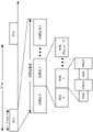
Fig. 3B is a block diagram conceptually illustrating an example SS hierarchy that synchronizes an example of a communication hierarchy. As shown in fig. 3B, the SS tier may include a set of SS bursts, which may include a plurality of SS bursts (identified as SS burst 0 through SS burst B-1, where B is the maximum number of repetitions of an SS burst that may be sent by a base station). As further shown, each SS burst may include one or more SS blocks (identified as SS block 0 through SS block (b)max_SS-1) Wherein b ismax_SS-1Is the maximum number of SS blocks that can be carried by an SS burst). In some aspects, different SS blocks may be beamformed in different ways. The wireless node may send the set of SS bursts periodically, such as every X milliseconds, as shown in fig. 3B. In some aspects, the set of SS bursts may have a fixed or dynamic length, shown as Y milliseconds in fig. 3B.
The set of SS bursts shown in fig. 3B is an example of a set of synchronous communications, and other sets of synchronous communications may be used in conjunction with the techniques described herein. Further, the SS blocks shown in fig. 3B are examples of sets of synchronous communications, and other synchronous communications may be used in conjunction with the techniques described herein.
In some aspects, SS blocks include resources that carry a PSS, SSs, PBCH, and/or other synchronization signals (e.g., Tertiary Synchronization Signals (TSS)) and/or synchronization channels. In some aspects, multiple SS blocks are included in an SS burst, and the PSS, SSs, and/or PBCH may be the same between each SS block of the SS burst. In some aspects, a single SS block may be included in an SS burst. In some aspects, an SS block may be at least four symbol periods in length, where each symbol carries one or more of PSS (e.g., occupies one symbol), SSs (e.g., occupies one symbol), and/or PBCH (e.g., occupies two symbols).
In some aspects, as shown in fig. 3B, the symbols of the SS blocks are consecutive. In some aspects, the symbols of the SS block are discontinuous. Similarly, in some aspects, one or more SS blocks of an SS burst may be transmitted in consecutive radio resources (e.g., consecutive symbol periods) during one or more time slots. Additionally or alternatively, one or more SS blocks of an SS burst may be transmitted in non-contiguous radio resources.
In some aspects, an SS burst may have a burst period, and thus the base station may transmit SS blocks of the SS burst according to the burst period. In other words, the SS block may repeat during each SS burst. In some aspects, the set of SS bursts may have a burst set period, and thus the base station may transmit SS bursts of the set of SS bursts according to a fixed burst set period. In other words, an SS burst may be repeated during each set of SS bursts.
The BS may transmit system information (e.g., System Information Blocks (SIBs)) on a Physical Downlink Shared Channel (PDSCH) in certain time slots. The base station may transmit control information/data on a Physical Downlink Control Channel (PDCCH) in C symbol periods of the slot, where B may be configurable for each slot. The base station may transmit traffic data and/or other data on the PDSCH in the remaining symbol periods of each slot.
As noted above, fig. 3A and 3B are provided as examples. Other examples are possible and may differ from the examples described with respect to fig. 3A and 3B.
Fig. 4 shows an example slot format 410 with a normal cyclic prefix. The available time-frequency resources may be divided into resource blocks. Each resource block may cover a set of subcarriers (e.g., 12 subcarriers) in one slot and may include multiple resource elements. Each resource element may cover one subcarrier in one symbol period (e.g., in units of time) and may be used to transmit one modulation symbol, which may be real or complex.
An interlace may be used for each of the downlink and uplink for FDD in certain telecommunication systems (e.g., NR). For example, Q interlaces may be defined with indices of 0 through Q-1, where Q may be equal to 4, 6, 8, 10, or some other value. Each interlace may include slots spaced apart by Q frames. Specifically, the interlace Q may include time slots Q, Q + Q, Q +2Q, etc., where Q ∈ { 0., Q-1 }.
The UE may be located within the coverage of multiple BSs. One of the BSs may be selected to serve the UE. The serving BS may be selected based at least in part on various criteria (e.g., received signal strength, received signal quality, path loss, etc.). The received signal quality may be quantified by a signal-to-noise-and-interference ratio (SINR), or a Reference Signal Received Quality (RSRQ), or some other metric. The UE may operate in a dominant interference scenario, where the UE may observe high interference from one or more interfering BSs.
Although aspects of the examples described herein may be associated with NR or 5G technologies, aspects of the disclosure may be applied with other wireless communication systems. A New Radio (NR) may refer to a radio configured to operate according to a new air interface (e.g., in addition to an Orthogonal Frequency Division Multiple Access (OFDMA) -based air interface) or a fixed transport layer (e.g., in addition to an Internet Protocol (IP)). In aspects, NR may utilize OFDM with CP (referred to herein as cyclic prefix OFDM or CP-OFDM) and/or SC-FDM on the uplink, CP-OFDM may be utilized on the downlink, and support for half-duplex operation using Time Division Duplex (TDD) is included. In aspects, the NR may utilize OFDM with CP on the uplink (referred to herein as CP-OFDM) and/or discrete fourier transform spread orthogonal frequency division multiplexing (DFT-s-OFDM), for example, may utilize CP-OFDM on the downlink and include support for half-duplex operation using TDD. NR may include enhanced mobile broadband (eMBB) services targeting wide bandwidths (e.g., 80 megahertz (MHz) and greater), millimeter wave (mmW) targeting high carrier frequencies (e.g., 60 gigahertz (GHz)), massive MTC (MTC) targeting non-backward compatible MTC technologies, and/or mission critical targeting ultra-reliable low latency communication (URLLC) services.
In some aspects, a single component carrier bandwidth of 100MHZ may be supported. The NR resource blocks may span 12 subcarriers having a subcarrier bandwidth of 60 or 120 kilohertz (kHz) in 0.1 millisecond (ms) duration. Each radio frame may include 40 slots and may have a length of 10 ms. Thus, each slot may have a length of 0.25 ms. Each time slot may indicate a link direction (e.g., DL or UL) for data transmission, and the link direction for each time slot may be dynamically switched. Each slot may include DL/UL data as well as DL/UL control data.
Beamforming may be supported and beam directions may be dynamically configured. MIMO transmission with precoding may also be supported. MIMO configuration in DL may support up to 8 transmit antennas, with multi-layer DL transmitting up to 8 streams and up to 2 streams per UE. Multi-layer transmission with up to 2 streams per UE may be supported. Aggregation of multiple cells with up to 8 serving cells may be supported. Alternatively, the NR may support a different air interface than the OFDM-based interface. The NR network may comprise entities such as central units or distributed units.
As noted above, fig. 4 is provided as an example. Other examples are possible and may differ from the example described with respect to fig. 4.
Synchronization signals (e.g., PSS, SSS, Tertiary Synchronization Signal (TSS), PBCH, synchronization signal blocks, etc.) may be transmitted at particular frequency locations defined by the synchronization grid. For example, in a frequency band associated with frequency f, possible frequency locations for transmitting synchronization signals may include f + Nd, where d is the value of the synchronization grid and N is an integer. The synchronization grid may be used in 5G-NR because the channel bandwidth and synchronization signal digital scheme is variable in 5G-NR, which means that the 100kHz channel grid used in LTE may not always be ideal. Herein, "synchronization signal" may be used interchangeably with "synchronization signal block" and "SS/PBCH block".
In 5G-NR, various digital schemes can be supported for the synchronization signal. For example, subcarrier spacings of 15kHz and/or 30kHz may be supported for frequency bands below 6GHz, and subcarrier spacings of 120kHz and/or 240kHz may be supported for frequency bands above 6 GHz. In some frequency bands, multiple digital schemes of synchronization signals may be employed. For example, one operator may use a 15kHz synchronization signal, while another operator may use a 30kHz synchronization signal.
When performing initial access, the UE may scan frequency locations until the UE recognizes a synchronization signal. For example, assuming each possible numerology, the UE may search for possible frequency locations until a synchronization signal is identified. This may result in high cell search complexity and long initial access delay, as the UE must check multiple digital schemes at each frequency location until a synchronization signal is identified.
The techniques and apparatus described herein may reduce the number of hypotheses or searches associated with identifying synchronization signals for frequency bands associated with multiple digital schemes for synchronization signals. For example, some techniques and apparatus described herein may perform a synchronous scan of an initial access procedure using a table that identifies a single number scheme for each potential frequency location. Some of the techniques and apparatus described herein may use a table that identifies frequency locations of synchronization signals for digital schemes of a frequency band, and identifies a subset of possible frequency locations for one of the digital schemes of the frequency band. In this way, at a given frequency location, the UE may only need to check a single digital scheme or a reduced number of digital schemes for synchronization signals. Therefore, the search complexity of the initial access procedure is reduced. Furthermore, by using the table, the number of candidate frequency locations for the digital scheme for a given synchronization signal may be reduced, which reduces the time delay associated with cell search and initial access.
Fig. 5 is a diagram illustrating an example 500 of performing a synchronization scan based at least in part on a synchronization signal location table identifying frequency locations for each digital scheme of a frequency band in accordance with various aspects of the present disclosure. Fig. 5 describes operations performed with respect to a frequency band, which may include a 4G-LTE frequency band, a 5G-NR frequency band, frequency bands of different radio access technologies, and/or combinations thereof. For the purposes of fig. 5, it is assumed that the frequency band is associated with two different digital schemes of 15kHz and 30 kHz. However, in some aspects, the frequency band may be associated with any combination of different digital schemes (e.g., 30kHz and 60kHz, 120kHz and 240kHz, etc.).
As shown in fig. 5 and by reference numeral 505, UE120 may store a synchronization signal location table (shown as a sync signal location table). The synchronization signal location table may include data identifying a plurality of sets of frequency locations and corresponding digital schemes associated with the sets of frequency locations. Here, the synchronization signal position table indicates that the odd frequency position set is associated with a digital scheme of 15kHz (e.g., a default digital scheme of frequency bands). Further, the synchronization signal position table indicates that the set of even frequency positions is associated with a 30kHz digital scheme. For example, assume that the frequency band is associated with frequency f. In that case, the odd frequency locations may include f + d, f +3d, f +5d, etc., where d is a synchronization grid of frequency bands. Similarly, even frequency locations may include f, f +2d, f +4d, and so on. In some aspects, the synchronization signal position table may identify a synchronization signal pattern (e.g., a synchronization signal block pattern) for scanning synchronization signals of a particular digital scheme. For example, different digital schemes may be associated with different synchronization signal patterns. UE120 may scan for synchronization signal blocks of a particular digital scheme according to a corresponding pattern. In some aspects, the synchronization grid may be constructed according to a default digital scheme of frequency bands, which is described in more detail below.
By assigning a single digit scheme to each frequency location, cell search complexity and initial access delay are reduced. For example, UE120 may search only a single number scheme at each frequency location, rather than searching each number scheme associated with a frequency band at each frequency location, as described in more detail below.
In some aspects, the synchronization signal location table may identify a plurality of digital schemes for a given frequency location. For example, the synchronization signals of the first digital scheme may use all frequency positions of the synchronization signal position table, and the synchronization signals of the second digital scheme may use a subset of the frequency positions of the synchronization signal position table (e.g., every other frequency position, every third frequency position, etc.). Thus, the number of hypotheses for the synchronization signal sweep is reduced compared to using all frequency positions for both digital schemes.
In some aspects, the synchronization signal position table may involve more than two different digital schemes. Additionally or alternatively, the synchronization signal position table may not divide the frequency positions evenly between the two digital schemes. For example, one number scheme (e.g., a default number scheme, a more commonly used number scheme, a higher priority number scheme, etc.) may be associated with a greater number of frequency locations as compared to another number scheme (e.g., a non-default number scheme, a less commonly used number scheme, a lower priority number scheme, etc.). This may reduce cell search complexity and initial access delay for one digital scheme while providing a frequency location for a synchronization signal for another digital scheme.
In some aspects, the synchronization signal location table may be based at least in part on a synchronization frequency grid. The synchronization grid of the synchronization frequency grid may be based at least in part on a default synchronization number scheme of the frequency band, and the default synchronization number scheme may be assigned to a location of the grid by default. For example, the synchronization grid may be equal to the default synchronous digital scheme. Additionally or alternatively, at least one synchronous frequency location on the grid may be used for another synchronous digital scheme. For example, at least one synchronization frequency location may not be used for the default synchronization digital scheme, or two synchronization digital schemes may be used at the at least one synchronization frequency location.
As indicated by reference numeral 510, BS 110 may be associated with a 30kHz digital scheme for synchronization signals provided by BS 110. For example, the carrier or cell provided by BS 110 may be associated with a 30kHz digital scheme. Thus, and as indicated by reference numeral 515, the base station may provide synchronization signals at even frequency locations. This is possible because in this example, the even frequency locations of the frequency band are specified for the 30kHz synchronization signal digital scheme according to the synchronization signal location table. In some aspects, UE120 and BS 110 may be aware of the synchronization signal location table. For example, the synchronization signal location table may be specified in a standard or specification.
As indicated by reference numeral 520, the UE120 may perform a synchronization scan in the frequency band. For example, UE120 may perform a synchronization scan as part of an initial access procedure. When performing the synchronization scan, the UE120 may not specifically know the frequency location in which the synchronization signal is transmitted. Accordingly, UE120 may scan for frequency locations according to a synchronization signal location table based at least in part on a digital scheme associated with the frequency band, as described in more detail below.
As indicated by reference numeral 525, the UE120 may first scan for odd frequency locations. For example, UE120 may identify odd frequency locations using the table and based at least in part on the 15kHz numerology being the default numerology for the frequency bands. In some aspects, UE120 may perform the scan using the mode identified by the table for the 15kHz digital scheme. By scanning for odd frequency locations first, UE120 completes scanning for frequency locations associated with the most likely digit scheme (e.g., the default digit scheme) first, and then proceeds with other digit schemes. Of course, other orders for scanning frequency locations are possible. As indicated by reference numeral 530, the UE120 determines that no synchronization signal is found in the odd frequency locations.
As indicated by reference numeral 535, the UE120 may scan for even frequency locations (i.e., locations associated with a 30kHz digital scheme) according to the table. For example, after exhausting odd frequency locations, UE120 may begin scanning for even frequency locations. In some aspects, the UE120 may scan for even frequency locations using the pattern for the 30kHz digital scheme identified by the table. In some aspects, UE120 may not first scan for frequency locations associated with a default number scheme. For example, the UE120 may perform progressive scanning (e.g., f + d, f +2d, f +3d, etc.) along the frequency band. Even when such progressive scanning is performed, the initial access delay can be improved compared to scanning each digital scheme at each frequency location, because a reduced number of digital schemes are scanned.
As indicated by reference numeral 540, the UE120 may identify the synchronization signal while scanning for even frequency locations. Accordingly, the UE120 may perform initial access using the identified synchronization signal. In this way, UE search complexity is reduced. Furthermore, the number of frequency location candidates for a given numerology may be reduced, thereby providing shorter cell search and initial access delay.
In some aspects, the UE120 may perform a synchronization scan in a non-standalone (NSA) mode. In NSA mode, UE120 may perform a synchronization scan based at least in part on signaling from BS 110. For example, the signaling may identify a digital scheme of synchronization signals to be transmitted in the NSA cell of BS 110 and to be detected by UE 120. In such a case, UE120 may perform a synchronization scan based at least in part on the identified number scheme. For example, UE120 may determine a synchronization grid according to the identified number scheme (e.g., the synchronization grid may be equal to the identified number scheme), and may search for a frequency band based at least in part on the synchronization grid. In this way, BS 110 may overlay a synchronization signal location table, which may provide increased flexibility for NSA cells with different synchronous digital schemes.
As noted above, fig. 5 is provided as an example. Other examples are possible and may differ from the example described with respect to fig. 5
Fig. 6 is a diagram illustrating an example process 600 performed, for example, by a UE, in accordance with various aspects of the present disclosure. The example process 600 is an example in which a user equipment (e.g., UE 120) performs a synchronization scan based at least in part on a synchronization signal location table identifying a single digital scheme for each frequency location.
As shown in fig. 6, in some aspects, process 600 may include: the identification frequency band is associated with a first numerology and a second numerology for synchronization (block 610). For example, the user equipment may identify that the frequency band is associated with a first numerology and a second numerology for synchronization (e.g., for transmission of synchronization signal blocks). In some aspects, a frequency band may be associated with more than two numerical schemes. The user equipment may identify a frequency band based at least in part on the stored data to perform a synchronous scan in the frequency band, as described in more detail below.
As shown in fig. 6, in some aspects, process 600 may include: performing a synchronization scan using the stored data to detect a synchronization signal block, wherein the stored data comprises data for a plurality of frequency locations of a frequency band, wherein the synchronization scan is performed with respect to a first set of frequency locations of the plurality of frequency locations associated with a first digital scheme, and wherein the synchronization scan is performed with respect to a second set of frequency locations of the plurality of frequency locations associated with a second digital scheme, wherein the second set of frequency locations comprises an appropriate subset of the plurality of frequency locations (block 620). For example, the user device may use the stored data to perform a synchronous scan. As described in more detail above, the stored data may include a synchronization signal location table. The stored data may include data regarding a plurality of frequency locations of the frequency band, which may be divided into two or more sets of frequency locations. For example, each set of frequency locations may be associated with a single number scheme. The user equipment may perform a synchronous scan with respect to a first set of frequency locations associated with a first digital scheme and/or with respect to a second set of frequency locations associated with a second digital scheme. For example, the user equipment may first perform a synchronous scan with respect to the first digital scheme and may subsequently perform a synchronous scan with respect to the second digital scheme.
In some aspects, the first set of frequency locations and the second set of frequency locations do not overlap. In some aspects, frequency locations in the first set of frequency locations alternate with frequency locations in the second set of frequency locations. In some aspects, the frequency bands are associated with frequencies, the first set of frequency locations are associated with one of odd frequency offsets from the frequencies or even frequency offsets from the frequencies, and the second set of frequency locations are associated with the other of the odd frequency offsets or the even frequency offsets.
In some aspects, the first and second numerologies have a plurality of numerologies associated with the frequency bands, and the plurality of numerologies are associated with respective non-overlapping sets of frequency locations. In some aspects, the synchronization signal block includes at least one of: primary Synchronization Signal (PSS), Secondary Synchronization Signal (SSS), Tertiary Synchronization Signal (TSS), or Physical Broadcast Channel (PBCH).
In some aspects, the stored data identifies a plurality of frequency locations and indicates respective numerical schemes associated with the plurality of frequency locations. In some aspects, the stored data identifies a numerical scheme for each frequency location. In some aspects, the first set of frequency locations has a different number of frequency locations than the second set of frequency locations. In some aspects, a frequency location of the plurality of frequency locations is determined according to a synchronization grid that identifies intervals of the plurality of frequency locations. In some aspects, the user equipment is in a non-standalone mode, and a frequency location of the plurality of frequency locations is determined from the synchronization grid in combination with an indication received by the user equipment indicating that the synchronization grid is to be used to determine the plurality of frequency locations in the non-standalone mode. In some aspects, the stored data is shared between the user device and a network to which the user device is connected.
In some aspects, the first set of frequency locations is associated with a first interval and the second set of frequency locations is associated with a second interval different from the first interval. In some aspects, the first set of frequency locations includes all of the plurality of frequency locations. In some aspects, the synchronization scan is performed with respect to a first set of frequency locations using a first pattern, and wherein the synchronization scan is performed with respect to a second set of frequency locations using a second pattern. In some aspects, the first pattern corresponds to a first numerology and the second pattern corresponds to a second numerology. In some aspects, the first numerology is associated with a first subcarrier spacing and the second numerology is associated with a second subcarrier spacing.
Although fig. 6 shows exemplary blocks of the process 600, in some aspects the process 600 may include additional blocks, fewer blocks, different blocks, or blocks arranged in a different manner than those depicted in fig. 6. Additionally or alternatively, two or more of the blocks of the process 600 may be performed in parallel.
The foregoing disclosure provides illustration and description, but is not intended to be exhaustive or to limit aspects to the precise form disclosed. Modifications and variations are possible in light of the above disclosure or may be acquired from practice of various aspects.
As used herein, the term component is intended to be broadly interpreted as hardware, firmware, or a combination of hardware and software. As used herein, a processor is implemented in hardware, firmware, or a combination of hardware and software.
Some aspects are described herein in connection with a threshold. As used herein, satisfying a threshold may refer to a value greater than a threshold, greater than or equal to a threshold, less than or equal to a threshold, not equal to a threshold, and the like.
It will be apparent that the systems and/or methods described herein may be implemented in various forms of hardware, firmware, or combinations of hardware and software. The actual specialized control hardware or software code used to implement the systems and/or methods is not limiting of various aspects. Thus, the operation and behavior of the systems and/or methods were described herein without reference to the specific software code-it being understood that software and hardware may be designed to implement the systems and/or methods based, at least in part, on the description herein.
Even if specific combinations of features are recited in the claims and/or disclosed in the description, these combinations are not intended to limit the disclosure of possible aspects. Indeed, many of these features may be combined in ways not specifically recited in the claims and/or specifically disclosed in the specification. Although each dependent claim listed below may depend directly on only one claim, the disclosure of possible aspects includes a combination of each dependent claim with every other claim in the set of claims. A phrase referring to "at least one of a list of items" refers to any combination of those items, including a single member. For example, "at least one of a, b, or c" is intended to encompass any combination of a, b, c, a-b, a-c, b-c, and a-b-c, as well as multiples of the same element (e.g., any other ordering of a, b, and c), a-a-a, a-a-b, a-a-c, a-b-b, a-c-c, b-b-b, b-b-c, c-c, and c-c-c, or a, b, and c).
No element, act, or instruction used herein should be construed as critical or essential unless explicitly described as such. In addition, as used herein, the articles "a" and "an" are intended to include one or more items, and may be used interchangeably with "one or more. Further, as used herein, the terms "set" and "group" are intended to include one or more items (e.g., related items, unrelated items, combinations of related items and unrelated items, etc.) and may be used interchangeably with "one or more. Where only one item is intended, the term "one" or similar language is used. Further, as used herein, the terms "having," "has," "having," and/or the like are intended to be open-ended terms. Further, the phrase "based on" is intended to mean "based, at least in part, on" unless explicitly stated otherwise.
Claims (26)
1. A method of wireless communication performed by a user equipment, comprising:
identifying that a frequency band is associated with a first numerology and a second numerology for transmission of a synchronization signal block; and
performing a synchronization scan at a plurality of frequency locations of the frequency band to detect a synchronization signal block of the first digital scheme or the second digital scheme,
wherein the synchronous scanning is performed with respect to a first set of frequency locations of the plurality of frequency locations associated with the first digital scheme, and
wherein the synchronous scanning is performed with respect to a second set of frequency locations of the plurality of frequency locations associated with the second digital scheme,
wherein the second set of frequency locations comprises an appropriate subset of frequency locations of the plurality of frequency locations.
2. The method of claim 1, wherein the first set of frequency locations and the second set of frequency locations do not overlap.
3. The method of claim 1, wherein frequency locations in the first set of frequency locations alternate with frequency locations in the second set of frequency locations.
4. The method of claim 1, wherein the frequency band is associated with a frequency,
wherein the first set of frequency locations is associated with one of an odd frequency offset from the frequency or an even frequency offset from the frequency, and
wherein the second set of frequency locations is associated with the other of the odd frequency offset or the even frequency offset.
5. The method of claim 1, wherein the first numerology and the second numerology have a plurality of numerologies associated with the frequency band,
wherein the plurality of digital schemes are associated with respective non-overlapping sets of frequency locations.
6. The method of claim 1, wherein the synchronization signal block contains at least one of: primary Synchronization Signal (PSS), Secondary Synchronization Signal (SSS), Tertiary Synchronization Signal (TSS), or Physical Broadcast Channel (PBCH).
7. The method of claim 1, wherein the first set of frequency locations has a different number of frequency locations than the second set of frequency locations.
8. The method of claim 1, wherein a frequency location of the plurality of frequency locations is determined according to a synchronization grid identifying intervals of the plurality of frequency locations.
9. The method of claim 8, wherein the user equipment is in a non-standalone mode; and is
Wherein a frequency location of the plurality of frequency locations is determined according to the synchronization grid in combination with an indication received by the user equipment indicating that the synchronization grid is to be used for determining the plurality of frequency locations in the non-standalone mode.
10. The method of claim 1, wherein the first set of frequency locations is associated with a first interval and the second set of frequency locations is associated with a second interval different from the first interval.
11. The method of claim 1, wherein the first set of frequency locations comprises all of the plurality of frequency locations.
12. The method of claim 1, wherein the synchronous scan is performed with respect to the first set of frequency locations using a first pattern, and wherein the synchronous scan is performed with respect to the second set of frequency locations using a second pattern.
13. The method of claim 12, wherein the first pattern corresponds to the first numerology and the second pattern corresponds to the second numerology.
14. The method of claim 1, wherein the first numerology is associated with a first subcarrier spacing and the second numerology is associated with a second subcarrier spacing.
15. A User Equipment (UE) for wireless communication, comprising:
a memory; and
one or more processors operatively coupled to the memory, the memory and the one or more processors configured to:
identifying that a frequency band is associated with a first numerology and a second numerology for transmission of a synchronization signal block; and
performing a synchronization scan at a plurality of frequency locations of the frequency band to detect a synchronization signal block of the first digital scheme or the second digital scheme,
wherein the synchronous scanning is performed with respect to a first set of frequency locations of the plurality of frequency locations associated with the first digital scheme, and
wherein the synchronous scanning is performed with respect to a second set of frequency locations of the plurality of frequency locations associated with the second digital scheme,
wherein the second set of frequency locations comprises an appropriate subset of frequency locations of the plurality of frequency locations.
16. The UE of claim 15, wherein the synchronization signal block contains at least one of: primary Synchronization Signal (PSS), Secondary Synchronization Signal (SSS), Tertiary Synchronization Signal (TSS), or Physical Broadcast Channel (PBCH).
17. The UE of claim 15, wherein the first set of frequency locations has a different number of frequency locations than the second set of frequency locations.
18. The UE of claim 15, wherein the first set of frequency locations is associated with a first interval and the second set of frequency locations is associated with a second interval different from the first interval.
19. The UE of claim 15, wherein the first set of frequency locations comprises all of the plurality of frequency locations.
20. The UE of claim 15, wherein the synchronization scan is performed with respect to the first set of frequency locations using a first pattern, and wherein the synchronization scan is performed with respect to the second set of frequency locations using a second pattern.
21. A non-transitory computer-readable medium storing one or more instructions for wireless communication, the one or more instructions comprising:
one or more instructions that, when executed by one or more processors of a User Equipment (UE), cause the one or more processors to:
identifying that a frequency band is associated with a first numerology and a second numerology for transmission of a synchronization signal block; and
performing a synchronization scan at a plurality of frequency locations of the frequency band to detect a synchronization signal block of the first digital scheme or the second digital scheme,
wherein the synchronous scanning is performed with respect to a first set of frequency locations of the plurality of frequency locations associated with the first digital scheme, and
wherein the synchronous scanning is performed with respect to a second set of frequency locations of the plurality of frequency locations associated with the second digital scheme,
wherein the second set of frequency locations comprises an appropriate subset of frequency locations of the plurality of frequency locations.
22. The non-transitory computer-readable medium of claim 21, wherein the first set of frequency locations has a different number of frequency locations than the second set of frequency locations.
23. The non-transitory computer-readable medium of claim 21, wherein the first set of frequency locations is associated with a first interval and the second set of frequency locations is associated with a second interval different from the first interval.
24. An apparatus for wireless communication, comprising:
means for identifying that a frequency band is associated with a first numerology and a second numerology for transmission of a synchronization signal block; and
means for performing a synchronization scan at a plurality of frequency locations of the frequency band to detect a synchronization signal block of the first digital scheme or the second digital scheme,
wherein the synchronous scanning is performed with respect to a first set of frequency locations of the plurality of frequency locations associated with the first digital scheme, and
wherein the synchronous scanning is performed with respect to a second set of frequency locations of the plurality of frequency locations associated with the second digital scheme,
wherein the second set of frequency locations comprises an appropriate subset of frequency locations of the plurality of frequency locations.
25. The apparatus of claim 24, wherein the first set of frequency locations is associated with a first interval and the second set of frequency locations is associated with a second interval different from the first interval.
26. The apparatus of claim 24, wherein the synchronous scan is performed with respect to the first set of frequency locations using a first pattern, and wherein the synchronous scan is performed with respect to the second set of frequency locations using a second pattern.
Priority Applications (1)
| Application Number | Priority Date | Filing Date | Title |
|---|---|---|---|
| CN202111483423.XA CN114143868B (en) | 2017-09-08 | 2018-09-07 | Techniques and apparatus for synchronization signal scanning based at least in part on a synchronization grid |
Applications Claiming Priority (5)
| Application Number | Priority Date | Filing Date | Title |
|---|---|---|---|
| US201762556077P | 2017-09-08 | 2017-09-08 | |
| US62/556,077 | 2017-09-08 | ||
| US16/123,784 | 2018-09-06 | ||
| US16/123,784 US11751147B2 (en) | 2017-09-08 | 2018-09-06 | Techniques and apparatuses for synchronization signal scanning based at least in part on a synchronization raster |
| PCT/US2018/049833 WO2019051150A1 (en) | 2017-09-08 | 2018-09-07 | Techniques and apparatuses for synchronization signal scanning based at least in part on a synchronization raster |
Related Child Applications (1)
| Application Number | Title | Priority Date | Filing Date |
|---|---|---|---|
| CN202111483423.XA Division CN114143868B (en) | 2017-09-08 | 2018-09-07 | Techniques and apparatus for synchronization signal scanning based at least in part on a synchronization grid |
Publications (2)
| Publication Number | Publication Date |
|---|---|
| CN111096004A CN111096004A (en) | 2020-05-01 |
| CN111096004B true CN111096004B (en) | 2021-11-30 |
Family
ID=65631951
Family Applications (2)
| Application Number | Title | Priority Date | Filing Date |
|---|---|---|---|
| CN201880057885.5A Active CN111096004B (en) | 2017-09-08 | 2018-09-07 | Method and device for synchronous signal scanning based on synchronous grid |
| CN202111483423.XA Active CN114143868B (en) | 2017-09-08 | 2018-09-07 | Techniques and apparatus for synchronization signal scanning based at least in part on a synchronization grid |
Family Applications After (1)
| Application Number | Title | Priority Date | Filing Date |
|---|---|---|---|
| CN202111483423.XA Active CN114143868B (en) | 2017-09-08 | 2018-09-07 | Techniques and apparatus for synchronization signal scanning based at least in part on a synchronization grid |
Country Status (8)
| Country | Link |
|---|---|
| US (2) | US11751147B2 (en) |
| EP (1) | EP3679748A1 (en) |
| JP (2) | JP7210551B2 (en) |
| KR (1) | KR20200044828A (en) |
| CN (2) | CN111096004B (en) |
| BR (1) | BR112020004699A2 (en) |
| SG (1) | SG11202000569WA (en) |
| WO (1) | WO2019051150A1 (en) |
Families Citing this family (3)
| Publication number | Priority date | Publication date | Assignee | Title |
|---|---|---|---|---|
| EP3567761B1 (en) | 2017-09-11 | 2021-11-17 | LG Electronics Inc. | Method for receiving ssb according to sync raster, and user equipment |
| JP7037594B2 (en) | 2020-03-26 | 2022-03-16 | アンリツ株式会社 | Radio wave propagation measuring device and its synchronization signal search method |
| JP7141422B2 (en) * | 2020-03-26 | 2022-09-22 | アンリツ株式会社 | Radio Wave Propagation Measuring Device and its Synchronization Signal Searching Method |
Citations (5)
| Publication number | Priority date | Publication date | Assignee | Title |
|---|---|---|---|---|
| CN102404840A (en) * | 2010-09-13 | 2012-04-04 | 株式会社Ntt都科摩 | Node in wireless system and method for time and frequency synchronizing nodes in wireless system |
| US20130028150A1 (en) * | 2006-08-08 | 2013-01-31 | Research In Motion Limited | Method and System for Wireless Communication in Multiple Operating Environments |
| US20150103733A1 (en) * | 2006-10-17 | 2015-04-16 | Sassan Ahmadi | Base station and method for configuring sub-frames for relay-node operations |
| CN105722184A (en) * | 2014-12-23 | 2016-06-29 | 英特尔公司 | Method of processing received digitized signals and mobile radio communication terminal device |
| WO2016137532A1 (en) * | 2015-02-26 | 2016-09-01 | Intel IP Corporation | Systems, methods and devices for radio access technology coordination |
Family Cites Families (30)
| Publication number | Priority date | Publication date | Assignee | Title |
|---|---|---|---|---|
| CA2859980C (en) | 2008-12-26 | 2016-04-12 | Sharp Kabushiki Kaisha | Base station device, mobile station device, communication system, and communication method |
| CN103795668B (en) | 2012-11-02 | 2017-08-18 | 电信科学技术研究院 | A kind of signal processing method, base station, terminal and system |
| CN107005960B (en) | 2014-09-24 | 2020-07-07 | 交互数字专利控股公司 | Channel usage indication and synchronization for LTE operation in unlicensed frequency bands |
| EP3266255B1 (en) * | 2015-03-06 | 2021-06-16 | Telefonaktiebolaget LM Ericsson (publ) | Methods and device for improved cell synchronization |
| CN107836129B (en) | 2015-07-06 | 2020-04-14 | 华为技术有限公司 | Data transmission method, wireless network equipment and communication system |
| CN107925976B (en) * | 2015-09-01 | 2021-09-21 | 株式会社Ntt都科摩 | User device, radio base station, and radio communication method |
| US11089579B2 (en) * | 2016-01-13 | 2021-08-10 | Samsung Electronics Co., Ltd. | Method and apparatus for supporting multiple services in advanced MIMO communication systems |
| ES2909239T3 (en) * | 2016-01-15 | 2022-05-05 | Ntt Docomo Inc | User terminal, wireless base station and wireless communication method |
| US10477537B2 (en) | 2016-02-11 | 2019-11-12 | Qualcomm Incorporated | Multi-PRB operation for narrowband systems |
| US10716020B2 (en) * | 2016-02-23 | 2020-07-14 | Samsung Electronics Co., Ltd. | Method and apparatus for measurement reference signal |
| EP3840277B1 (en) * | 2016-04-25 | 2022-12-07 | Electronics and Telecommunications Research Institute | Method for transmitting discovery signals and method for receiving discovery signals |
| KR101988574B1 (en) * | 2016-06-12 | 2019-06-12 | 엘지전자 주식회사 | Method for receiving signals and wireless device thereof |
| US10973046B2 (en) * | 2016-07-02 | 2021-04-06 | Lg Electronics Inc. | Downlink signal reception method and user equipment, and downlink signal transmission method and base station |
| KR102329949B1 (en) * | 2016-07-05 | 2021-11-23 | 한국전자통신연구원 | Transmission method and apparatus using numerology, and method and apparatus for scheduling using numerology |
| RU2721757C1 (en) * | 2016-07-26 | 2020-05-22 | Гуандун Оппо Мобайл Телекоммьюникейшнз Корп., Лтд. | Method and device for transmitting information |
| CN107733829B (en) * | 2016-08-12 | 2021-11-02 | 大唐移动通信设备有限公司 | Method and equipment for sending and detecting synchronous signal |
| EP3282633B1 (en) | 2016-08-12 | 2020-08-05 | ASUSTek Computer Inc. | Method and apparatus for determining numerology bandwidth in a wireless communication system |
| WO2018062771A1 (en) * | 2016-09-29 | 2018-04-05 | Samsung Electronics Co., Ltd. | Methods and apparatus for supporting multiple services in wireless communication system |
| EP3520275A1 (en) | 2016-09-30 | 2019-08-07 | Sony Mobile Communications Inc. | Subcarrier spacing selection for synchronization signals |
| US10992510B2 (en) * | 2016-09-30 | 2021-04-27 | Motorola Mobility Llc | Method and apparatus for synchronization signals and random access for flexible radio communication |
| WO2018062891A1 (en) * | 2016-09-30 | 2018-04-05 | 엘지전자(주) | Method for transmitting and receiving synchronization signal in wireless communication system and apparatus for method |
| WO2018073683A1 (en) | 2016-10-10 | 2018-04-26 | Nokia Technologies Oy | Synchronization of narrowband and wideband user equipment |
| WO2018084209A1 (en) | 2016-11-02 | 2018-05-11 | 株式会社Nttドコモ | User terminal and wireless communication method |
| JP2020031254A (en) * | 2016-12-27 | 2020-02-27 | シャープ株式会社 | Terminal device, base station device, communication method, and integrated circuit |
| US10623161B2 (en) * | 2017-01-05 | 2020-04-14 | Telefonaktiebolaget Lm Ericsson (Publ) | Allocation of sync signals with alternative features |
| CN108289332A (en) * | 2017-01-09 | 2018-07-17 | 夏普株式会社 | Frequency location indicating means, base station and the user equipment of wireless signal |
| WO2018199653A1 (en) * | 2017-04-28 | 2018-11-01 | 엘지전자 주식회사 | Method and wireless device for performing measurement in nr for 5g |
| KR102352364B1 (en) * | 2017-06-15 | 2022-01-18 | 주식회사 아이티엘 | Method and apparatus for wideband opration in nr communication system |
| EP3944546A1 (en) * | 2017-08-10 | 2022-01-26 | Huawei Technologies Co., Ltd. | Transmitting device, receiving device and methods thereof |
| CN109392081B (en) * | 2017-08-11 | 2021-10-19 | 华为技术有限公司 | Communication method, device and system |
-
2018
- 2018-09-06 US US16/123,784 patent/US11751147B2/en active Active
- 2018-09-07 CN CN201880057885.5A patent/CN111096004B/en active Active
- 2018-09-07 EP EP18779504.2A patent/EP3679748A1/en active Pending
- 2018-09-07 JP JP2020512799A patent/JP7210551B2/en active Active
- 2018-09-07 WO PCT/US2018/049833 patent/WO2019051150A1/en unknown
- 2018-09-07 KR KR1020207006316A patent/KR20200044828A/en not_active Application Discontinuation
- 2018-09-07 BR BR112020004699-0A patent/BR112020004699A2/en unknown
- 2018-09-07 SG SG11202000569WA patent/SG11202000569WA/en unknown
- 2018-09-07 CN CN202111483423.XA patent/CN114143868B/en active Active
-
2023
- 2023-01-10 JP JP2023001878A patent/JP2023052292A/en active Pending
- 2023-07-20 US US18/355,783 patent/US20230362850A1/en active Pending
Patent Citations (5)
| Publication number | Priority date | Publication date | Assignee | Title |
|---|---|---|---|---|
| US20130028150A1 (en) * | 2006-08-08 | 2013-01-31 | Research In Motion Limited | Method and System for Wireless Communication in Multiple Operating Environments |
| US20150103733A1 (en) * | 2006-10-17 | 2015-04-16 | Sassan Ahmadi | Base station and method for configuring sub-frames for relay-node operations |
| CN102404840A (en) * | 2010-09-13 | 2012-04-04 | 株式会社Ntt都科摩 | Node in wireless system and method for time and frequency synchronizing nodes in wireless system |
| CN105722184A (en) * | 2014-12-23 | 2016-06-29 | 英特尔公司 | Method of processing received digitized signals and mobile radio communication terminal device |
| WO2016137532A1 (en) * | 2015-02-26 | 2016-09-01 | Intel IP Corporation | Systems, methods and devices for radio access technology coordination |
Also Published As
| Publication number | Publication date |
|---|---|
| EP3679748A1 (en) | 2020-07-15 |
| BR112020004699A2 (en) | 2020-09-15 |
| JP2023052292A (en) | 2023-04-11 |
| WO2019051150A1 (en) | 2019-03-14 |
| CN114143868A (en) | 2022-03-04 |
| US20190082402A1 (en) | 2019-03-14 |
| CN114143868B (en) | 2023-12-26 |
| JP2020533845A (en) | 2020-11-19 |
| CN111096004A (en) | 2020-05-01 |
| US20230362850A1 (en) | 2023-11-09 |
| US11751147B2 (en) | 2023-09-05 |
| JP7210551B2 (en) | 2023-01-23 |
| SG11202000569WA (en) | 2020-03-30 |
| KR20200044828A (en) | 2020-04-29 |
Similar Documents
| Publication | Publication Date | Title |
|---|---|---|
| CN111615846B (en) | System information monitoring | |
| US20190387532A1 (en) | System information block transmission scheduling | |
| US11050598B2 (en) | Carrier information signaling in a 5G network | |
| CN111656724B (en) | Wireless communication method, base station and user equipment | |
| CN111919482A (en) | Radio link management under partial handover of bandwidth | |
| US20230362850A1 (en) | Techniques and apparatuses for synchronization signal scanning based at least in part on a synchronization raster | |
| CN114830573A (en) | HARQ feedback reporting for cross-carrier scheduling | |
| CN113454932A (en) | Method and apparatus for cross-link interference measurement and reporting | |
| CN111279649B (en) | Techniques and apparatus for physical downlink control channel downlink control information to search space mapping | |
| CN112314037A (en) | Conflict management | |
| US11265130B2 (en) | Techniques for shared radio frequency spectrum channel configuration | |
| US20210028900A1 (en) | Tracking reference signal configuration | |
| CN112075110A (en) | Method and apparatus for concurrent communication in a network | |
| US11617163B2 (en) | Avoiding collisions with reference signals | |
| CN114631349A (en) | Paging indicator | |
| CN113647028A (en) | Sounding reference signal resource determination for physical uplink shared channel with configured grant |
Legal Events
| Date | Code | Title | Description |
|---|---|---|---|
| PB01 | Publication | ||
| PB01 | Publication | ||
| SE01 | Entry into force of request for substantive examination | ||
| SE01 | Entry into force of request for substantive examination | ||
| REG | Reference to a national code |
Ref country code: HK Ref legal event code: DE Ref document number: 40027537 Country of ref document: HK |
|
| GR01 | Patent grant | ||
| GR01 | Patent grant |