EP3840277B1 - Method for transmitting discovery signals and method for receiving discovery signals - Google Patents
Method for transmitting discovery signals and method for receiving discovery signals Download PDFInfo
- Publication number
- EP3840277B1 EP3840277B1 EP21151527.5A EP21151527A EP3840277B1 EP 3840277 B1 EP3840277 B1 EP 3840277B1 EP 21151527 A EP21151527 A EP 21151527A EP 3840277 B1 EP3840277 B1 EP 3840277B1
- Authority
- EP
- European Patent Office
- Prior art keywords
- frequency
- resource
- numerology
- synchronization signal
- discovery signal
- Prior art date
- Legal status (The legal status is an assumption and is not a legal conclusion. Google has not performed a legal analysis and makes no representation as to the accuracy of the status listed.)
- Active
Links
- 238000000034 method Methods 0.000 title claims description 244
- 201000003042 peeling skin syndrome Diseases 0.000 claims 5
- 229920001467 poly(styrenesulfonates) Polymers 0.000 claims 5
- 238000005259 measurement Methods 0.000 description 35
- 230000005540 biological transmission Effects 0.000 description 20
- 238000004891 communication Methods 0.000 description 15
- 239000000969 carrier Substances 0.000 description 11
- 238000005516 engineering process Methods 0.000 description 9
- 238000001914 filtration Methods 0.000 description 8
- 230000007423 decrease Effects 0.000 description 6
- 230000006870 function Effects 0.000 description 6
- 238000010187 selection method Methods 0.000 description 6
- 239000000470 constituent Substances 0.000 description 5
- 238000001514 detection method Methods 0.000 description 5
- 238000005070 sampling Methods 0.000 description 5
- 238000010408 sweeping Methods 0.000 description 5
- 238000013461 design Methods 0.000 description 3
- 230000000694 effects Effects 0.000 description 3
- 230000002776 aggregation Effects 0.000 description 2
- 238000004220 aggregation Methods 0.000 description 2
- 238000013507 mapping Methods 0.000 description 2
- 238000012545 processing Methods 0.000 description 2
- 108010076504 Protein Sorting Signals Proteins 0.000 description 1
- 239000008186 active pharmaceutical agent Substances 0.000 description 1
- 230000015556 catabolic process Effects 0.000 description 1
- 125000004122 cyclic group Chemical group 0.000 description 1
- 238000006731 degradation reaction Methods 0.000 description 1
- 230000001419 dependent effect Effects 0.000 description 1
- 230000009977 dual effect Effects 0.000 description 1
- VJYFKVYYMZPMAB-UHFFFAOYSA-N ethoprophos Chemical compound CCCSP(=O)(OCC)SCCC VJYFKVYYMZPMAB-UHFFFAOYSA-N 0.000 description 1
- PCHJSUWPFVWCPO-UHFFFAOYSA-N gold Chemical group [Au] PCHJSUWPFVWCPO-UHFFFAOYSA-N 0.000 description 1
- 230000007774 longterm Effects 0.000 description 1
- 238000007726 management method Methods 0.000 description 1
- 238000012544 monitoring process Methods 0.000 description 1
- 238000013468 resource allocation Methods 0.000 description 1
- 238000012772 sequence design Methods 0.000 description 1
- 238000001228 spectrum Methods 0.000 description 1
Images


Classifications
-
- H—ELECTRICITY
- H04—ELECTRIC COMMUNICATION TECHNIQUE
- H04B—TRANSMISSION
- H04B7/00—Radio transmission systems, i.e. using radiation field
- H04B7/24—Radio transmission systems, i.e. using radiation field for communication between two or more posts
- H04B7/26—Radio transmission systems, i.e. using radiation field for communication between two or more posts at least one of which is mobile
-
- H—ELECTRICITY
- H04—ELECTRIC COMMUNICATION TECHNIQUE
- H04J—MULTIPLEX COMMUNICATION
- H04J11/00—Orthogonal multiplex systems, e.g. using WALSH codes
- H04J11/0069—Cell search, i.e. determining cell identity [cell-ID]
- H04J11/0073—Acquisition of primary synchronisation channel, e.g. detection of cell-ID within cell-ID group
-
- H—ELECTRICITY
- H04—ELECTRIC COMMUNICATION TECHNIQUE
- H04J—MULTIPLEX COMMUNICATION
- H04J11/00—Orthogonal multiplex systems, e.g. using WALSH codes
- H04J11/0069—Cell search, i.e. determining cell identity [cell-ID]
- H04J11/0076—Acquisition of secondary synchronisation channel, e.g. detection of cell-ID group
-
- H—ELECTRICITY
- H04—ELECTRIC COMMUNICATION TECHNIQUE
- H04L—TRANSMISSION OF DIGITAL INFORMATION, e.g. TELEGRAPHIC COMMUNICATION
- H04L27/00—Modulated-carrier systems
- H04L27/26—Systems using multi-frequency codes
-
- H—ELECTRICITY
- H04—ELECTRIC COMMUNICATION TECHNIQUE
- H04L—TRANSMISSION OF DIGITAL INFORMATION, e.g. TELEGRAPHIC COMMUNICATION
- H04L27/00—Modulated-carrier systems
- H04L27/26—Systems using multi-frequency codes
- H04L27/2601—Multicarrier modulation systems
- H04L27/2602—Signal structure
-
- H—ELECTRICITY
- H04—ELECTRIC COMMUNICATION TECHNIQUE
- H04L—TRANSMISSION OF DIGITAL INFORMATION, e.g. TELEGRAPHIC COMMUNICATION
- H04L27/00—Modulated-carrier systems
- H04L27/26—Systems using multi-frequency codes
- H04L27/2601—Multicarrier modulation systems
- H04L27/2602—Signal structure
- H04L27/26025—Numerology, i.e. varying one or more of symbol duration, subcarrier spacing, Fourier transform size, sampling rate or down-clocking
-
- H—ELECTRICITY
- H04—ELECTRIC COMMUNICATION TECHNIQUE
- H04L—TRANSMISSION OF DIGITAL INFORMATION, e.g. TELEGRAPHIC COMMUNICATION
- H04L27/00—Modulated-carrier systems
- H04L27/26—Systems using multi-frequency codes
- H04L27/2601—Multicarrier modulation systems
- H04L27/2602—Signal structure
- H04L27/261—Details of reference signals
- H04L27/2613—Structure of the reference signals
-
- H—ELECTRICITY
- H04—ELECTRIC COMMUNICATION TECHNIQUE
- H04L—TRANSMISSION OF DIGITAL INFORMATION, e.g. TELEGRAPHIC COMMUNICATION
- H04L27/00—Modulated-carrier systems
- H04L27/26—Systems using multi-frequency codes
- H04L27/2601—Multicarrier modulation systems
- H04L27/2647—Arrangements specific to the receiver only
- H04L27/2655—Synchronisation arrangements
- H04L27/2689—Link with other circuits, i.e. special connections between synchronisation arrangements and other circuits for achieving synchronisation
- H04L27/2692—Link with other circuits, i.e. special connections between synchronisation arrangements and other circuits for achieving synchronisation with preamble design, i.e. with negotiation of the synchronisation sequence with transmitter or sequence linked to the algorithm used at the receiver
-
- H—ELECTRICITY
- H04—ELECTRIC COMMUNICATION TECHNIQUE
- H04L—TRANSMISSION OF DIGITAL INFORMATION, e.g. TELEGRAPHIC COMMUNICATION
- H04L5/00—Arrangements affording multiple use of the transmission path
- H04L5/0001—Arrangements for dividing the transmission path
- H04L5/0003—Two-dimensional division
- H04L5/0005—Time-frequency
- H04L5/0007—Time-frequency the frequencies being orthogonal, e.g. OFDM(A), DMT
-
- H—ELECTRICITY
- H04—ELECTRIC COMMUNICATION TECHNIQUE
- H04L—TRANSMISSION OF DIGITAL INFORMATION, e.g. TELEGRAPHIC COMMUNICATION
- H04L5/00—Arrangements affording multiple use of the transmission path
- H04L5/003—Arrangements for allocating sub-channels of the transmission path
- H04L5/0048—Allocation of pilot signals, i.e. of signals known to the receiver
- H04L5/005—Allocation of pilot signals, i.e. of signals known to the receiver of common pilots, i.e. pilots destined for multiple users or terminals
-
- H—ELECTRICITY
- H04—ELECTRIC COMMUNICATION TECHNIQUE
- H04L—TRANSMISSION OF DIGITAL INFORMATION, e.g. TELEGRAPHIC COMMUNICATION
- H04L5/00—Arrangements affording multiple use of the transmission path
- H04L5/003—Arrangements for allocating sub-channels of the transmission path
- H04L5/0053—Allocation of signaling, i.e. of overhead other than pilot signals
-
- H—ELECTRICITY
- H04—ELECTRIC COMMUNICATION TECHNIQUE
- H04W—WIRELESS COMMUNICATION NETWORKS
- H04W48/00—Access restriction; Network selection; Access point selection
- H04W48/08—Access restriction or access information delivery, e.g. discovery data delivery
- H04W48/10—Access restriction or access information delivery, e.g. discovery data delivery using broadcasted information
-
- H—ELECTRICITY
- H04—ELECTRIC COMMUNICATION TECHNIQUE
- H04W—WIRELESS COMMUNICATION NETWORKS
- H04W48/00—Access restriction; Network selection; Access point selection
- H04W48/08—Access restriction or access information delivery, e.g. discovery data delivery
- H04W48/12—Access restriction or access information delivery, e.g. discovery data delivery using downlink control channel
-
- H—ELECTRICITY
- H04—ELECTRIC COMMUNICATION TECHNIQUE
- H04W—WIRELESS COMMUNICATION NETWORKS
- H04W8/00—Network data management
- H04W8/005—Discovery of network devices, e.g. terminals
-
- H—ELECTRICITY
- H04—ELECTRIC COMMUNICATION TECHNIQUE
- H04B—TRANSMISSION
- H04B7/00—Radio transmission systems, i.e. using radiation field
- H04B7/24—Radio transmission systems, i.e. using radiation field for communication between two or more posts
- H04B7/26—Radio transmission systems, i.e. using radiation field for communication between two or more posts at least one of which is mobile
- H04B7/2603—Arrangements for wireless physical layer control
- H04B7/2606—Arrangements for base station coverage control, e.g. by using relays in tunnels
Definitions
- the present invention relates to methods for transmitting/receiving discovery signals.
- a wireless communication system supports a frame structure according to the technical specification.
- a 3GPP (3rd Generation Partnership Project) LTE (Long Term Evolution) system supports frame structures of three types.
- the frame structures of three types include a type 1 frame structure applicable to FDD (frequency division duplex), a type 2 frame structure applicable to TDD (time division duplex), and a type 3 frame structure for a transmission of a unlicensed frequency band.
- a TTI transmission time interval
- a basic time unit with which an encoded data packet is transmitted through a physical layer signal means a basic time unit with which an encoded data packet is transmitted through a physical layer signal.
- a TTI of the LTE system is composed of one subframe. That is, a time domain length of a PRB (physical RB (resource block)) pair as a minimum unit of a resource allocation is 1 ms.
- a physical signal and a channel are mainly defined by a subframe unit.
- a CRS cell-specific reference signal
- a PDCCH physical downlink control channel
- a PDSCH physical downlink shared channel
- PUCCH physical uplink control channel
- PUSCH physical uplink shared channel
- a PSS primary synchronization signal
- SSS secondary synchronization signal
- ZTE "Considerations on Channel Raster for NB-IoT", 3GPP DRAFT; R1-160051 CHANNEL RASTER, 3RD GENERATION PARTNERSHIP PROJECT (3GPP), MOBILE COMPETENCE CENTRE; 650, ROUTE DES LUCIOLES; F-06921 SOPHIA-ANTIPOLIS CEDEX; FRANCE, vol. RAN WG1, no. Budapest, HU; 11 January 2016 , describes considerations on channel raster for NB-IoT. A channel raster of 100 kHz can be reused.
- a 100 kHz channel raster should exactly hit the centre subcarrier of NB-PSS/NB-SSS and the centre subcarrier is the 6 th or 7 th subcarrier of the narrowband including consecutive 12 subcarriers.
- a technique for transmitting/receiving the signal for a heterogeneous frame structure based on a plurality of numerologies is required.
- the present invention provides a method for transmitting discovery signals, performed by a base station operating a cell as described in claim 1 and a method for receiving discovery signals, performed by a terminal as described by claim 6. Further embodiments of the invention are described in the dependent claims.
- 'A or B' may include 'A', 'B', or 'A and B'.
- a terminal may indicate a mobile terminal, a mobile station, an advanced mobile station, a high reliability mobile station, a subscriber station, a portable subscriber station, an access terminal, user equipment, and the like, or may include whole or partial functions of the mobile terminal, the mobile station, the advanced mobile station, the high reliability mobile station, the subscriber station, the portable subscriber station, the access terminal, the user equipment, and the like.
- a base station may indicate an advanced base station, a high reliability base station (HR-BS), a node B, an evolved node B (eNodeB), an access point, a radio access station, a base transceiver station, a mobile multihop relay (MMR)-BS, a relay station executing a base station function, a high reliability relay station executing a base station function, a repeater, a macro base station, a small base station, and the like, or may include whole or partial functions of the advanced base station, the HR-BS, the nodeB, the eNodeB, the access point, the radio access station, the transceiver base station, the MMR-BS, the relay station, the high reliability relay station, the repeater, the macro base station, the small base station, and the like.
- HR-BS high reliability base station
- eNodeB evolved node B
- MMR mobile multihop relay
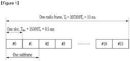
- FIG. 1 is a view showing a type 1 frame structure of an LTE system.
- Each subframe has the length of 1 ms, and one subframe consists of two slots of 0.5 ms length.
- One slot consists of seven time domain symbols (for example, an OFDM (orthogonal frequency division multiplexing) symbol) in a case of a normal CP (cyclic prefix), and consists of six time domain symbols (for example, the OFDM symbol) in a case of an extended CP.
- OFDM orthogonal frequency division multiplexing
- the time domain symbol may be the OFDM symbol, or an SC (single carrier)-FDMA (frequency division multiple access) symbol.
- SC single carrier
- FDMA frequency division multiple access
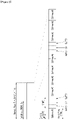
- FIG. 2 is a view showing a type 2 frame structure of an LTE system.
- one radio frame consists of a downlink (DL) subframe, an uplink (UL) subframe, and a special subframe.
- the special subframe exists between the downlink subframe and the uplink subframe, and includes a DwPTS (downlink pilot time slot), a GP (guard period), and an UpPTS (uplink pilot time slot).
- DwPTS downlink pilot time slot
- GP guard period
- UpPTS uplink pilot time slot
- One radio frame includes two special subframes in a case in which a downlink-uplink switching periodicity is 5 ms, and includes one special subframe in a case in which the downlink-uplink switching periodicity is 10 ms.
- FIG. 2 shows a case in which the downlink-uplink switching periodicity is 5 ms, and subframe 1 and subframe 6 are the special subframes.
- the DwPTS is used for cell search, synchronization, or channel estimation.
- the GP is a period for removing an interference generated in the uplink of the base station due to a multipath delay difference of the terminals.
- the transmission of the PRACH (physical random access channel) or the SRS (sounding reference signal) is possible.
- the wireless communication system may be applied to various wireless communication networks.
- the wireless communication system may be applied to a current wireless access technology (RAT: radio access technology)-based wireless communication network, or the 5G and beyond 5G wireless communication networks.
- RAT radio access technology
- the 3GPP develops a new RAT-based 5G technical specification satisfying IMT(International Mobile Telecommunications)-2020 requirements, and this new RAT is referred to as NR (new radio).
- NR new radio
- the NR-based wireless communication system is described as an example. However, it is merely an example, the present invention is not limited thereto, and the present invention may be applied to various wireless communication systems.
- NR uses a wide range of frequency bands in order to increase the transmission capacity.
- the WRC World Radiocommunication Conference
- ITU International Telecommunication Union
- the WRC-19 agenda includes consideration of a 24.25-86 GHz band as the candidate frequency band for the IMT-2020.
- the 3GPP considers the frequency band from 1 GHz or less to 100 GHz as the NR candidate frequency band.
- OFDM orthogonal frequency division multiplexing
- filtered OFDM GFDM (generalized frequency division multiplexing)
- FBMC filter bank multicarrier
- UFMC universal filtered multicarrier
- the waveform technology for the wireless access a case using a CP-based OFDM (CP-OFDM) is assumed.
- CP-OFDM CP-based OFDM
- the CP-OFDM technology applied with windowing and/or filtering or spread spectrum OFDM technology for example, DFT-spread OFDM
- Table 1 below represents an example of an OFDM system parameter configuration for the NR system.
- the frequency band of 700 MHz-100 GHz is divided into three regions (i.e., a low frequency band (-6 GHz), a high frequency band (3-40 GHz), and a super high frequency band (30-100 GHz)), and different OFDM numerologies from each other are applied to each frequency band.
- one of main factors determining subcarrier spacing of the OFDM system is a carrier frequency offset (CFO) suffered by a receiving terminal.
- the carrier frequency offset (CFO) has a characteristic that it increases in proportion to the operation frequency due to a Doppler effect and a phase drift. Accordingly, to block performance degradation by the carrier frequency offset, the subcarrier spacing must be increased in proportion to the operation frequency. In contrast, if the subcarrier spacing is very large, there is a drawback that a CP overhead increases. Accordingly, the subcarrier spacing must be defined as an appropriate value considering the channel and the RF (radio frequency) characteristic for each frequency band.
- the subcarrier spacing of SETs A, B, and C of Table 1 is 16.875 kHz, 67.5 kHz, and 270 kHz, respectively, which is approximately in proportion to a target operation frequency, and is configured to make a difference of four times.
- Table 1 Set A Set B Set C Carrier frequency Low freq. (-6 GHz) High freq. (3-40 GHz) Very high freq. (30-100 GHz)
- the values of the subcarrier spacing used in Table 1 are merely exemplary, and the subcarrier spacing may be designed with as many other values as necessary.
- 15 kHz of the conventional LTE subcarrier spacing is used as a base numerology
- the subcarrier spacing (for example, 30 kHz, 60 kHz, 120 kHz, 240 kHz, etc.) scaled with multiplication by power of two based on this may be used for the numerology scaling.
- Table 2 (as an example of the OFDM system parameter configuration).
- To configure the subcarrier spacing to make the difference by multiplication by power of two between the subcarrier spacing of the heterogeneous numerologies may be advantageous to the operation (for example, carrier aggregation, dual connectivity, or multiplexing of the heterogeneous numerologies within one carrier) between the heterogeneous numerologies.
- Table 2 Set A Set B Set C Set D Set E Subcarrier spacing 15 kHz 30 kHz 60 kHz 120 kHz 240 kHz CP overhead 6.7 % 6.7 % % % % % % % % % % Number of OFDM symbols per 1 ms 14 28 56 112 224
- One numerology may be basically used for one cell (or one carrier), and may be used for a special time-frequency resource within one carrier.
- the heterogeneous numerology may be used for the different operation frequency bands from each other as illustrated in Table 1, and may be used to support different service types from each other in the same frequency band.
- the SET A of Table 1 can be used for the eMBB (enhanced mobile broadband) service of the 6 GHz band or less
- the SET B or the SET C of Table 1 can be used for the URLLC (ultra-reliable low latency communication) service of the 6 GHz band or less.
- the numerology having the smaller subcarrier spacing than that of the subcarrier spacing of the basic numerology may be used.
- the subcarrier spacing of the basic numerology is 15 kHz
- the subcarrier spacing of 7.5 kHz or 3.75 kHz may be considered.
- a terminal To discover a cell (or a carrier) in initial cell search process, a terminal must be able to detect the synchronization signal of the corresponding cell for all candidate frequencies on the carrier raster in the frequency band to which the corresponding cell belongs.
- the synchronization signal may be transmitted with reference to one frequency among the candidate frequencies.
- the carrier raster spacing is 100 kHz
- the DC (direct current) subcarrier as the center of the subcarriers to which the synchronization signal is transmitted is aligned on a specific graduation point of the carrier raster.
- the terminal may derive the center frequency position of the cell (the carrier) from the frequency value of the corresponding carrier raster graduation point.
- the terminal may obtain the center frequency of the cell (or the carrier) without help of the base station.
- the new carrier raster may be designed.
- the carrier raster may mean a group of the candidate reference frequencies of the synchronization signal or may mean a group of the candidate center frequencies of the cell (or the carrier).
- the former and the latter can generally be separated from one another.
- the frequency spacing of the carrier raster may be determined as an integer multiple of the subcarrier spacing. This is referred to as a method M100.
- the raster spacing may be determined as an integer multiple of the multiplication of the subcarrier spacing and N. This is referred to as a method M101.
- the spacing of the carrier raster for a frequency band using the numerology having a subcarrier spacing of 15 kHz may be a multiple of 15 kHz by the method M100.
- the raster spacing may be a multiple of 180 kHz or may be 180 kHz itself by the method M101.
- FIG. 3 is a view showing a carrier raster and carrier allocation based on a method M101 or a method M102 according to an exemplary embodiment.
- FIG. 3 illustrate a case in which the carrier raster spacing is the same as the bandwidth occupied by one resource block as an exemplary embodiment of the method M101.
- the method M101 may perform the carrier allocation as there is no idle band (or band gap) between the carriers (Carrier 1, Carrier 2). This may be applied the same or a similar way when both of two adjacent carriers have an odd number of resource blocks.
- the raster spacing may be determined as the multiplication of the subcarrier spacing and N/2, that is, half of the bandwidth occupied by one resource block. This is referred to as a method M102.
- the raster search spacing may be 90 kHz.
- the exemplary embodiment of the method M102 is illustrated in (c) of FIG. 3 .
- the method M102 may perform the carrier allocation as there is no idle band (or the band gap) between the carriers (Carrier 1, Carrier 2).
- the center frequency position design is important. If, like the LTE downlink, when one subcarrier of the center frequency is defined as the DC (direct current) subcarrier and the DC subcarrier is excluded from the composition of resource blocks, even if the method M101 or the method M102 is used, the idle band may be inevitably generated between the carriers due to the frequency part occupied by the DC subcarrier. In contrast, like the LTE uplink, when the center frequency is defined as the middle between two subcarriers and the resource block is composed by using all subcarriers (however, the subcarrier of a guard band is excluded), the above-described effect of the method M101 or the method M102 may be obtained. This may also be established for the method described later.
- a plurality of numerologies may be used in one frequency band.
- one frequency band may mean a specific frequency range, and the specific frequency range may be wide or narrow.
- a specific frequency range may be the bandwidth of one carrier, may be one frequency band having a bandwidth of several to several hundreds of MHz, or may be a wider region than that.
- FIG. 4 is a view showing a case in which a plurality of numerologies are used in a common frequency band.
- FIG. 4 illustrates a case in which three heterogeneous numerologies (Numerology 1, Numerology 2, and Numerology 3) are used in a common frequency band.
- the subcarrier spacing of Numerology 2 is larger than the subcarrier spacing of Numerology 1
- the subcarrier spacing of Numerology 3 is larger than the subcarrier spacing of Numerology 2. This is expressed by the difference between the time domain of the resource grid lengths (the difference between the OFDM symbol lengths) or the difference between the frequency domain of the resource grid lengths in FIG. 4 .
- the subcarrier spacing of Numerology 1 is 15 kHz
- the subcarrier spacing of Numerology 2 and Numerology 3 may be 30 kHz and 60 kHz, respectively.
- a plurality of heterogeneous numerologies may be respectively used for the different carriers, and may be used together in one carrier.
- FIG. 4 illustrates a case in which Numerology 1 and Numerology 2 coexist within one carrier and Numerology 3 constitutes one carrier by itself.
- the carrier raster may be defined for each numerology. This is referred to as a method M110.
- an offset of the carrier raster graduation may be determined. This is referred to as a method M111.
- the carrier raster of Numerology 1 can have a 0 kHz offset and a 100 kHz spacing
- the carrier raster of Numerology 2 can have a 50 kHz offset and a 200 kHz spacing. That is, the frequency such as 100 kHz, 200 kHz, 300 kHz, etc. may be the center frequency candidates of Numerology 1, and the frequency such as 50 kHz, 250 kHz, 450 kHz, etc. may be the center frequency candidates of Numerology 2.
- the terminal when the terminal initially searches only the cell (or the carrier) having Numerology 2, the terminal only searches the candidate center frequencies having a 50 kHz offset and a 200 kHz spacing. In this case, the terminal may assume that Numerology 2 is applied to the entire or some region of the cell (or the carrier) of which the search is successful.
- the graduations of the carrier raster for the numerologies may be defined to have an inclusion relationship to each other. This is referred to as a method M112.
- the carrier raster of Numerology 1 may have a 0 kHz offset and a 100 kHz spacing
- the carrier raster of Numerology 2 may have a 0 kHz offset and a 200 kHz spacing.
- the frequency such as 100 kHz, 300 kHz, 500 kHz, etc. may be the center frequency candidates of Numerology 1
- the frequency such as 200 kHz, 400 kHz, 600 kHz, etc. may be the center frequency candidates of Numerology 1 and Numerology 2.
- the method M112 may reduce a number of the carrier raster graduation points to be searched by the terminal compared with the method M111.
- the terminal detects the cell in the frequency such as 200 kHz, 400 kHz, and 600 kHz
- a method to distinguish whether the cell detected by the terminal is based on Numerology 1 or Numerology 2 is required. This will be described in detail in 'synchronization signal design' part later.
- the frequency spacing of the carrier raster for the numerology may be determined to be proportional to the subcarrier spacing of each numerology. This is referred to as a method M113.
- the carrier raster spacing of Numerology 2 may be two times the carrier raster spacing of Numerology 1.
- the method M101 and the method M102 may be used as a method defining the carrier raster spacing.
- the method M113 may help to minimize the idle band between the carriers within the same band.
- FIG. 5 is a view showing a carrier raster and a carrier allocation based on a method M112 or a method M113 according to an exemplary embodiment.
- N2 the subcarrier spacing of Numerology 2
- N1 the subcarrier spacing of Numerology 1
- the carrier raster for Numerology 1 includes the carrier raster for Numerology 2 (N2) by the method M112, and the carrier raster spacing for Numerology 2 (N2) is two times the carrier raster spacing for Numerology 1 (N1) by the method M113.
- N RE the number of resource elements of one resource block in the frequency domain
- N1 and Numerology 2 N2
- the resource block of the carrier 2 Carrier 2 occupies the bandwidth that is wider than the resource block of the carrier 1 (Carrier 1) by two times.
- the method M101 is used to define the raster spacing. That is, the raster spacing of Numerology 1 (N1) is the same as the bandwidth occupied by one resource block of the carrier 1, and the raster spacing of Numerology 2 (N2) is the same as the bandwidth occupied by one resource block of the carrier 2.
- the carrier allocation may be performed as there is no idle band (or guard band) between the carriers (Carrier 1, Carrier 2).
- the carrier allocation may also be performed as there is no idle band between the carriers. Instead, as the carrier raster spacing is reduced, the cell search complexity may increase.
- one carrier raster may be commonly defined for the plurality of numerologies. This is referred to as a method M120.
- the carrier raster defined with reference to the numerology of the smallest subcarrier spacing within one frequency band may be used for the plurality of numerologies.
- the method M120 may increase the complexity compared with the method M112.
- the carrier raster may be defined for each frequency band. For example, it may be defined so that only numerology(ies) having the subcarrier spacing that is relatively large is used in the high frequency band. In this case, the carrier raster for the high frequency band may have the wider spacing than that of the carrier raster for the low frequency band.
- the terminal may need to assume the plurality of numerologies for one carrier raster graduation and the synchronization signal or the cell (or the carrier) thereof in the initial cell search process.
- the method M200 and the method M210 exist according to the relationship between the numerology of the synchronization signal and the numerology of the carrier.
- the method M200 is a method in which the numerology applied to the synchronization signal follows the numerology of the carrier to which the synchronization signal belongs.
- the method M200 because there is no interference between the synchronization signal and the signal of the adjacent frequency domain, the method M200 has a merit that it is not necessary to additionally set the guard band.
- the terminal may attempt the detection of the synchronization signal by each numerology for the plurality of numerologies candidates.
- the terminal may consider the numerology of the detected synchronization signal as the numerology of the carrier to which the detected synchronization signal belongs.
- the process thereof may be performed through the sampling, the filtering, and a correlator.
- the filtering may be low-pass filtering when the synchronization signal is disposed to be symmetric with reference of the center frequency like the LTE.
- the correlator may be implemented with an auto-correlator, a self-correlator, or a cross-correlator according to the characteristic of the synchronization signal sequence.
- a Zadoff-Chu sequence As a sequence of the synchronization signal, a Zadoff-Chu sequence, a Gold sequence, and the like may be used.
- the sequence of the synchronization signal may be defined for each OFDM symbol and may be a long sequence occupying the plurality of OFDM symbols.
- the method M201 is the method in which the time-frequency resource element configuration of the synchronization signal resource region is the same for the plurality of numerologies. That is, the method M201 is the method in which the resource element mapping of the synchronization signal is the same regardless of the numerology.
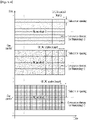
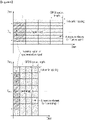
- FIG. 6 is a view showing a synchronization signal resource region based on a method M201 according to an exemplary embodiment.
- FIG. 6 illustrates a case in which the method M201 is applied to two numerologies (Numerology 1 and Numerology 2) that are different from each other.
- the sequence length of the synchronization signal is 6 and the subcarrier spacing of Numerology 2 is larger than the subcarrier spacing of Numerology 1.
- the resource region of the synchronization signal occupies one resource element (i.e., one OFDM symbol) in the time domain and occupies six continuous resource elements in the frequency domain.
- F BW,1 represents the bandwidth occupied by the synchronization signal applied with Numerology 1
- F BW,2 represents the bandwidth occupied by the synchronization signal applied with Numerology 2.
- F BW,2 is larger than F BW,1 .
- the complexity and the delay time for the initial cell search of the terminal may increase.
- a required sampling rate may increase. For example, when the subcarrier spacing of the carrier is 60 kHz, the high sampling rate of four times may be required compared with the case in which the subcarrier spacing is 15 kHz.
- the method M201 may be advantageous to beam sweeping-based transmission in the high frequency band.
- the resource region of the synchronization signal basically means a group of the resource elements in which the synchronization signal is mapped.
- the guard band may need to be inserted at both ends of the bandwidth of the synchronization signal.
- the resource region of the synchronization signal may mean the region including both the resource region where the synchronization signal is mapped and the guard band.
- the method M202 is a method defining the bandwidth so that the bandwidth occupied by the synchronization signal resource region is the same or similar regardless of the numerology.
- FIG. 7 is a view showing a numerology of a synchronization signal and a resource region of a synchronization signal based on a method M202 according to an exemplary embodiment.
- FIG. 7 illustrates a case in which the method M202 is applied to two different numerologies (Numerology 1 and Numerology 2).
- the subcarrier spacing (2*K) for Numerology 2 is two times the subcarrier spacing (K) for Numerology 1. That is, in FIG. 7 , it is assumed that the OFDM symbol length L for Numerology 1 is two times the OFDM symbol length L/2 for Numerology 2.
- the resource region of the synchronization signal includes eight resource elements in the frequency domain and one resource element in the time domain in the case of Numerology 1, and includes four resource elements in the frequency domain and three resource elements in the time domain in the case of Numerology 2.
- the method M202 has the merit that the terminal may apply the same filtering to the plurality of numerologies in the initial cell search process.
- the method M202 may transmit the synchronization signal to the narrow bandwidth regardless of the subcarrier spacing of the numerology.
- the sequence design considering this and the coexistence design with the other signals and channels considering this are required.
- the fact that the bandwidths of the synchronization signal resource region are similar regardless of the numerologies may mean that the bandwidths are sufficiently similar (for example, within a few subcarriers difference) in applying the common filtering to the plurality of numerologies through the terminal.
- a method for performing the mapping may be considered so that the time duration is also the same or similar regardless of the numerology as well as the bandwidth of the synchronization signal resource region. This is referred to as a method M203.
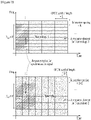
- FIG. 8 is a view showing a numerology of a synchronization signal and a resource region of a synchronization signal based on a method M203 according to an exemplary embodiment.
- FIG. 8 like the exemplary embodiment of FIG. 7 , it is assumed that the subcarrier spacing (2*K) for Numerology 2 is two times the subcarrier spacing (K) for Numerology 1. That is, in FIG. 8 , it is assumed that the OFDM symbol length L for Numerology 1 is two times the OFDM symbol length L/2 for Numerology 2.
- the resource region of the synchronization signal includes eight resource elements in the frequency domain and one resource element in the time domain in the case of Numerology 1, and includes four resource elements in the frequency domain and two resource elements in the time domain in the case of Numerology 2. That is, the bandwidth F BW,1 occupied by the synchronization signal resource region for Numerology 1 and the bandwidth F BW,2 occupied by the synchronization signal resource region for Numerology 2 are the same, and the time duration T occupied by the synchronization signal resource region for Numerology 1 and the time duration T occupied by the synchronization signal resource region for Numerology 2 are the same.
- the frequency resource region may be the same for the plurality of numerologies as well as the frequency bandwidth of the synchronization signal resource region.
- the synchronization signal may occupy the bandwidth of F BW,1 Hz or F BW,2 Hz at the center of the system bandwidth regardless of the numerology.
- the method M210 is a method in which the numerology applied to the synchronization signal is fixed regardless of the numerology of the carrier to which the synchronization signal belongs.
- FIG. 9 is a view showing a numerology of a synchronization signal and a resource region of a synchronization signal based on a method M210 according to an exemplary embodiment.
- FIG. 9 illustrates a case in which the synchronization signal of the carrier applied with Numerology 1 and the synchronization signal of the carrier applied with Numerology 2 both follow Numerology 1.
- the resource region for the synchronization signal includes eight resource elements in the frequency domain and one resource element in the time domain. That is, the bandwidth F and the time duration T occupied by the synchronization signal resource region for Numerology 1 are the same as the bandwidth F and the time duration T occupied by the synchronization signal resource region for Numerology 2.
- the method M210 may be applied within a specific frequency range.
- the method M210 may predetermine the numerology for the synchronization signal as one among the numerologies allowed within a specific frequency range. For example, the synchronization signal in the frequency band of 6 GHz or less may always be transmitted based on the numerology having the subcarrier spacing of 15 kHz.
- the terminal may search the synchronization signal through a single numerology in the initial cell search process.
- the terminal may explicitly or implicitly acquire the numerology of the carrier through the synchronization signal reception. Also, the terminal may obtain the numerology of the carrier through the signal or the channel (for example, PBCH) received by the terminal after the synchronization signal. In this case, the signal or the channel received by the terminal after the synchronization signal follows the same numerology as the numerology of the synchronization signal.
- an additional guard band may be inserted to both ends of the bandwidth of the synchronization signal.
- the plurality of numerologies may be multiplexed through the TDM (time division multiplexing), or may be multiplexed through the FDM (frequency division multiplexing) like the exemplary embodiment of FIG. 4 .
- a method hereinafter, 'method M220' in which a plurality of numerologies share one synchronization signal and a method (hereinafter, 'method M230') in which the synchronization signal is transmitted for each numerology may be used.
- the numerology of the synchronization signal may follow one among the plurality of numerologies within the carrier. This is referred to as a method M221.
- the method M221 will be described with reference to FIG. 10 .
- FIG. 10 is a view showing a numerology of a synchronization signal and a resource region of a synchronization signal for a carrier composed of a plurality of numerologies according to an exemplary embodiment.
- FIG. 10 illustrates a case in which two numerologies (Numerology 1, Numerology 2) are applied in one carrier.
- the synchronization signal resource region may be defined within the resource region to which the same numerology as the numerology (for example, Numerology 1) of the synchronization signal is applied.
- FIG. 10 illustrates the case in which the resource region for the synchronization signal includes six resource elements in the frequency domain and one resource element in the time domain.
- the numerology of the synchronization signal may be used as the base numerology within one carrier. That is, the terminal accessed to the corresponding carrier may receive the signal by using the base numerology within the specific time-frequency resource region before separately configured with a numerology.
- the synchronization signal may be defined at the center of the carrier bandwidth (for example, to be symmetrical based on the center frequency).
- the terminal may at least assume the same numerology as the numerology of the synchronization signal for the center bandwidth occupied with the synchronization signal.
- the above-described methods for example, the method M201, the method M202, the method M203, etc. may be used.
- the numerology of the synchronization signal may follow a predetermined numerology regardless of the numerologies of the carrier. This is referred to as a method M222.
- the numerology of each synchronization signal may follow the numerology of the resource region in which the synchronization signal is defined. This is referred to as a method M231.
- the method M231 may be considered as the method M200 being applied within one carrier.
- the configuration of the synchronization signal resource region may follow the above-described method (for example, the method M201, the method M202, the method M203, etc.).
- the numerology of all synchronization signals within one carrier may follow one among a plurality of numerologies constituting the carrier. This is referred to as a method M232.
- the numerology of all synchronization signals within one carrier may follow a predetermined numerology regardless of the numerology of the carrier. This is referred to as a method M233.
- a capability of the terminal may be considered.
- the method M220 may be used.
- a terminal supporting the eMBB and the URLLC may correspond to this.
- the terminal may use the different numerologies from each other for the synchronization signal reception and the data reception.
- the method M230 may be used for the terminal without the capability of receiving the plurality of numerologies.
- a low-cost terminal to support only a specific numerology for the mMTC transmission may correspond to this.
- the terminal uses the same numerology for the synchronization signal reception and the data reception.
- the method M220 and the method M230 may be combined and used.
- transmission timing and the periodicity of the synchronization signal may be the same for a plurality of numerologies.
- the transmission timing and the periodicity of the synchronization signal may be expressed by different equations for each frame structure.
- the initial cell search complexity of the terminal may be reduced.
- the different signals may be mapped to the resource region of the synchronization signal. That is, within the synchronization signal resource region, the synchronization signal and the signal (or the channel) other than the synchronization signal may coexist.
- the resource elements to which the synchronization signal is not mapped may be used for the transmission of the other signals (or the channels).
- the above-described synchronization signal may be limited to the usage searching the center frequency of the cell (or the carrier) in the initial cell search process of the terminal. In this case, in the frequency domain that does not support a standalone operation of the cell (or the carrier), the synchronization signal may not exist. Also, when the cell (or the carrier) is operated as an only secondary cell, the synchronization signal may not exist.
- the above-described synchronization signal may also be used for synchronization acquisition, synchronization tracking, and/or cell ID acquisition of the terminal as well as the center frequency search.
- the above-described synchronization signal may be used as a pilot for the channel estimation (or the data decoding).
- the synchronization signal when the synchronization signal is used for other uses as well as the center frequency search, the synchronization signal may be configured with a plurality of synchronization signals.
- the synchronization signal may be configured with a first synchronization signal and a second synchronization signal.
- the above-described methods for example, the method M200 to the method M210
- the above-described methods may only be applied to some of synchronization signals (for example, the first synchronization signal).
- the above-described methods (for example, the method M200 to the method M210) may be applied to the plurality of synchronization signals (for example, the first synchronization signal, the second synchronization signal).
- the synchronization signal resource region defined for the above-described methods (for example, the method M200 to the method M210) may include only some of synchronization signals in the former case and may include the plurality of synchronization signals in the latter case.
- the operation of the high frequency band and the operation of the low frequency band may be different from each other.
- transmit beamforming and/or receive beamforming may be applied.
- a beamforming may also be applied to the common signal and the control channel as well as the data channel.
- the signal may need to be received or transmitted several times through the beams having a plurality of different direction directivities.
- beam sweeping To transmit the signal applied with the beamforming through the different resources from each other in the time domain is referred to as beam sweeping.
- the entire coverage of the cell or the sector may be covered.
- the initial access procedure of the NR must support all the above-different beam operations.
- a downlink discovery signal and an uplink PRACH may be used.
- the discovery signal may be the downlink signal for the cell search, system information acquisition, beam acquisition and tracking, and so on of the terminal, and may be periodically transmitted to the terminal.
- a discovery signal occasion may be defined.
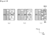
- FIG. 11 is a view showing a constituent element of a discovery signal according to an exemplary embodiment.
- the discovery signal occasion may consist of the synchronization signal and the PBCH, as illustrated in (a) of FIG. 11 .
- the synchronization signal may be used for the time-frequency synchronization, the cell ID acquisition, etc., and the PBCH may be used to transmit system information (SI) that is essential for the initial access.
- SI system information
- a cell (or a base station) that does not support the initial access may not transmit the PBCH. That is, the discovery signal occasion may not include the PBCH.
- the synchronization signal may be composed of a plurality of synchronization signals.
- the synchronization signal may consist of a primary synchronization signal (PSS) and a secondary synchronization signal (SSS).
- PSS primary synchronization signal
- SSS secondary synchronization signal
- the discovery signal occasion may consist of the synchronization signal, PBCH, and a beam reference signal (BRS).
- PBCH synchronization signal
- BRS beam reference signal
- the BRS may be used for beam or beam ID acquisition, RRM (radio resource management) measurement, and/or PBCH decoding.
- the TDM may be applied between the PBCH and the BRS. Also, for better PBCH decoding performance, as illustrated in (c) of FIG. 11 , the PBCH and the BRS may coexist in a common region.
- the discovery signal occasion may include the reference signal for CSI (channel state information) measurement and reporting, that is, a CSI-RS (reference signal).
- the discovery signal occasion may also include a separate reference signal for the beam tracking.
- the CSI-RS and/or the beam tracking reference signal may be set to be terminal specific (UE-specific).
- a transmission periodicity and an offset of the discovery signal occasion may be a fixed value that is predefined.
- M time-frequency resources exist for each of the synchronization signal, the PBCH, and/or the BRS within one discovery signal occasion periodicity.
- M is a natural number. That is, the element signals included in the discovery signal occasion may respectively use the M resources.
- the M resources for each element signal have the same bandwidth and the same time duration (for example, the same number of OFDM symbols).
- the beam sweeping may be applied to each of the synchronization signal, the PBCH, and/or the BRS through the plurality of resources.
- the discovery signal occasion may consist of a plurality of signal blocks.
- the resource occupied by one signal block is continuous in the time and frequency domains. That is, the resource occupied by one signal block may include time domain symbols that are continuous in the time domain.
- a method M300 and a method M310 may be considered according to the element signal constituting the signal blocks.
- the method M300 is a method in which the discovery signal occasion consists of the heterogeneous signal blocks. That is, the discovery signal occasion may consist of the synchronization signal block(s) and the PBCH block. In this case, when the BRS exists for the decoding of the PBCH, the BRS may be included in the PBCH block.
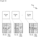
- FIG. 12 is a view showing a resource configuration of a discovery signal occasion based on a method M300 according to an exemplary embodiment.
- FIG. 12 illustrates a case in which the discovery signal occasion consists of three heterogeneous signal blocks (a first signal block, a second signal block, and a third signal block).
- the first signal block is the PSS block, and includes M PSS resources classified through the TDM.
- the second signal block is the SSS block and includes M SSS resources classified through the TDM.
- the third signal block is the PBCH block and includes M PBCH resources and/or M BRS resources classified through the TDM.
- the discovery signal occasion may be configured of two heterogeneous signal blocks (a first signal block and a second signal block).
- the first signal block is the PSS and the SSS block and includes the M PSS resources and the M SSS resources classified through the TDM.
- the second signal block is the PBCH block and includes the M PBCH resources and/or the M BRS resources classified through the TDM.
- the PSS resources and the SSS resources may be arranged to be crossed in the order of ⁇ PSS #0, SSS #0, PSS #1, SSS #1, ..., PSS # M-1, SSS # M-1 ⁇ in the time domain within the first signal block.
- the method M310 is a method in which the discovery signal occasion consists of the homogeneous signal block(s), that is, the discovery signal block(s). The method M310 will be described with reference to FIG. 13 .
- FIG. 13 is a view showing a resource composition of a discovery signal occasion based on a method M310 according to an exemplary embodiment.
- DS means the discovery signal.
- the discovery signal occasion consists of the M discovery signal block(s), and one discovery signal block includes one synchronization signal resource, one PBCH resource, and/or one BRS resource.
- FIG. 13 illustrates a case in which the synchronization signal consists of the PSS and the SSS and the TDM is applied between the PSS resource, the SSS resource, and the PBCH resource within each discovery signal block.
- One synchronization signal resource included in one discovery signal block is classified into the PSS resource and the SSS resource.
- the terminal When the terminal firstly receives the PSS and then receives the SSS next, it is advantageous that the PSS is transmitted earlier than the SSS in time within one discovery signal block.
- the TDM and/or the FDM may be applied between the signal blocks.
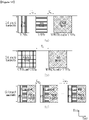
- FIG. 14 is a view showing a case in which a TDM is applied between signal blocks in a method M300 or a method M310 according to an exemplary embodiment.
- the TDM When the discovery signal occasion occupies only one sub-band, the TDM may be applied between the signal blocks. This case is illustrated in (a) of FIG. 14, (b) of FIG. 14, and (c) of FIG. 14 .
- both the TDM and the FDM may be applied among the signal blocks.
- (a) of FIG. 14 and (b) of FIG. 14 represent an exemplary embodiment of the method M300
- (c) of FIG. 14 represents an exemplary embodiment of the method M310.
- a time distance between the PSS block (including the M PSS resources) and the SSS block (including the M SSS resources) is T B,0
- the time distance between the SSS block and the PBCH block (including the M PBCH resources and/or the M BRS resources) is T B,1 .
- the time distance between the PSS/SSS block (including the M PSS resources and the M SSS resources) and the PBCH block (including the M PBCH resources and/or the M BRS resources) is T B .
- each discovery signal block includes one synchronization signal resource (the PSS resource, the SSS resource), one PBCH resource, and/or one BRS resource.
- the bandwidth(s) of the sub-bands occupied by one discovery signal occasion may all be the same. This bandwidth is referred to as cell search bandwidth.
- the synchronization signal bandwidth including the guard band may be the same as the PBCH bandwidth.
- the method M310 has some merits compared with the method M300.
- the PSS/SSS may help the decoding of the PBCH or the BRS-based RRM measurement.
- the method M300 must perform the beam sweeping for each signal block in the case of M>1, fast beamforming change is required.
- the method M310 may change the beamforming across the discovery signal blocks and may apply the same or similar beam within a discovery signal block, the beamforming change may less frequently occur.
- a relative distance (for example, the time domain distance and the frequency domain distance) among the m-th PSS resource, the m-th SSS resource, and the m-th PBCH resource may be changed depending on a beamforming mode, that is, the value of M.
- m is a resource index and is an integer greater than or equal to 0 and less than or equal to M-1. Accordingly, after the terminal receives the PSS, resource position information of the SSS or the PBCH may need to be provided from the base station to receive the SSS or the PBCH. For example, the terminal may also need to obtain the value of M through the PSS reception to know the resource position of the SSS or the PBCH.
- the relative distance (for example, the time domain distance and the frequency domain distance) between the m-th PSS resource, the m-th SSS resource, and the m-th PBCH resource is constant regardless of the value of M.
- the frequency domain distance between the resources means the relative distance between the frequency regions occupied by the resources. This may be applied to a case in which the frequency resources overlap with each other in the frequency domain.
- the time and the frequency distances between the PSS (or the PSS resource) and the SSS (or the SSS resource) included in the m-th discovery signal block generated by the base station are the same as the time and frequency distances between the PSS (or the PSS resource) and the SSS (or the SSS resource) included in the (m+1)-th discovery signal block generated in the base station.
- the time domain distance between the PSS resource and the SSS resource included in the m-th discovery signal block is the same as the time domain distance between the PSS resource and the SSS resource included in the (m+1)-th discovery signal block
- the frequency domain distance between the PSS resource and the SSS resource included in the m-th discovery signal block is the same as the frequency domain distance between the PSS resource and the SSS resource included in the (m+1)-th discovery signal block.
- the time and frequency distances between the SSS (or the SSS resource) and the PBCH (or the PBCH resource) included in the m-th discovery signal block are the same as the time and frequency distances between the SSS (or the SSS resource) and the PBCH (or the PBCH resource) included in the (m+1)-th discovery signal block.
- the time and frequency distances between the PSS (or the PSS resource) and the PBCH (or the PBCH resource) included in the m-th discovery signal block are the same as the time and frequency distances between the PSS (or the PSS resource) and the PBCH (or the PBCH resource) included in the (m+1)-th discovery signal block.
- the terminal may receive the SSS or the PBCH at the position determined within the discovery signal block (for example, the m-th discovery signal block) including the PSS resource (for example, the m-th PSS resource) in which the PSS is detected. That is, the terminal does not need to know the resource of all signal blocks constituting the discovery signal occasion, and it is sufficient to assume that one discovery signal block including the PSS resource of which the PSS is detected is transmitted. Therefore, according to the method M310, the terminal does not need to know the beamforming mode, that is, the value of M in the discovery signal receiving process for the initial cell search.
- the terminal may assume (or determine) a discovery signal measurement window (DMW) to receive the discovery signal occasion.
- DW discovery signal measurement window
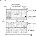
- FIG. 15 is a view showing a case in which a discovery signal occasion is transmitted in a discovery signal measurement window according to an exemplary embodiment.
- the terminal may monitor, find, and measure the discovery signal within the discovery signal measurement window.
- the terminal may monitor the PSS within the discovery signal measurement window.
- the terminal may find one or more PSS beam transmitted from the same cell.
- the terminal finds at least one PSS corresponding to at least one discovery signal block within the discovery signal measurement window, one among at least one PSS may be selected.
- a method (hereinafter, 'a first selection method') of selecting the PSS beam (or the PSS resource corresponding to the PSS beam) of which the reception performance is the best among the found PSS beam(s) may be used. Also, to select one among at least one found PSS beam, a method (hereinafter, 'a second selection method') performing the monitoring until the terminal finds one PSS beam (or the PSS resource corresponding to the PSS beam) satisfying a predetermined reception performance condition may be used.
- the first selection method provides higher reception performance compared with the second selection method, however discovery signal receiving complexity of the terminal may increase.
- the terminal may monitor the SSS or the PBCH at the position determined within the discovery signal block (for example, the m-th discovery signal block) corresponding to the PSS (for example, the PSS having the best reception performance or satisfying the predefined reception performance condition) selected by the first selection method or the second selection method.
- the discovery signal block for example, the m-th discovery signal block
- the PSS for example, the PSS having the best reception performance or satisfying the predefined reception performance condition
- FIG. 15 illustrates a case in which the discovery signal measurement window is continuously predetermined in the time-frequency domain within one DMW periodicity.
- the discovery signal measurement window may also be discontinuous in the time or frequency domain. That is, a plurality of resource blocks may constitute the discovery signal measurement window in the time domain or the frequency domain within one discovery signal measurement window periodicity. In this case, each resource block may mean a group of the continuous resources in the time domain and the frequency domain, and the resource blocks may not be adjacent in the time domain and/or the frequency domain.
- the terminal that is not connected by RRC may assume the discovery signal measurement window information (for example, a DMW duration and a DMW periodicity) as a predetermined value. That is, the terminal that is not connected to the base station by the RRC may determine the duration and the periodicity for the discovery signal measurement window based on the predefined duration value and periodicity value.
- the discovery signal measurement window periodicity for the terminal attempting the initial access may be defined as 5 ms like the LTE, and the discovery signal measurement window duration for the terminal may be defined as a fixed value of less than 5 ms.
- the terminal that is not connected by the RRC may monitor the discovery signal in the whole time instances.
- the RRC-connected terminal may receive the configuration of the discovery signal measurement window information (for example, the DMW duration and the DMW periodicity) from the base station.
- the discovery signal measurement window periodicity may be set to be longer than the value assumed by the terminal that is not connected by the RRC, and the discovery signal measurement window duration may be set to be shorter than the value assumed by the terminal that is not connected by the RRC.
- the periodicity and the duration of the discovery signal measurement window may be set as 40 ms and 2 ms, respectively.
- the base station may set the DMW periodicity for the terminal that is connected to the base station by the RRC as the value that is larger than the periodicity value that is predetermined for the terminal that is not connected to the base station by the RRC. Also, the base station may set the DMW duration for the terminal that is connected to the base station by the RRC as the value that is smaller than the duration value that is predetermined for the terminal that is not connected to the base station by the RRC.
- the RRC-connected terminal may not perform the discovery signal measurement. That is, the discovery signal measurement window information (for example, the DMW duration and the DMW periodicity) may be set to the terminal only when the terminal discovery signal measurement is necessary. Also, in this case, the RRC-connected terminal may assume the discovery signal measurement window information (for example, the DMW duration and the DMW periodicity) as the same value as the value assumed by the terminal that is not connected by the RRC.
- the discovery signal measurement window information for example, the DMW duration and the DMW periodicity
- the discovery signal measurement window information (for example, the DMW duration and the DMW periodicity) may be signaled as terminal specific (UE-specific).
- FIG. 15 illustrates a case in which all signals (for example, the M discovery signal blocks) constituting the discovery signal occasion are transmitted by the base station within the discovery signal measurement window.
- all signals for example, the M discovery signal blocks
- the terminal specific discovery signal measurement window only a part (for example, one or a plurality of discovery signal blocks) of the signals constituting the discovery signal occasion may be transmitted.
- no signal constituting the discovery signal occasion may be transmitted.
- a resource pool (hereinafter, 'a discovery signal resource pool') to transmit the discovery signal occasion may be defined. That is, the discovery signal occasion may be transmitted within a predefined discovery signal resource pool.
- the periodicity of the discovery signal occasion may not be separately defined, and the periodicity of the discovery signal resource pool may be vicariously defined.
- the base station may allocate a part or all of the resources belonging to the discovery signal resource pool predefined for the transmission of the discovery signal to at least one discovery signal block.
- FIG. 15 illustrates a case in which the base station allocates a part of the resources belonging to the discovery signal resource pool to the M discovery signal blocks constituting the discovery signal occasion.
- FIG. 15 illustrates a case in which the region of the discovery signal resource pool is identical to the region of the discovery signal measurement window.
- the region of the discovery signal resource pool and the region of the discovery signal measurement window may not be identical.
- the PRACH may be used for the random access of the terminal or the terminal discovery of the base station.
- the terminal may transmit the preamble or encoded signal through the PRACH.
- the operation related to the PRACH resource configuration method for the case using the method M310 will be described.
- the PRACH occasion may be defined.
- the resources occupied by one PRACH block are continuous in the time-frequency domain.
- FIG. 16 is a view showing a discovery signal and a PRACH resource composition based on a method M310 according to an exemplary embodiment.
- FIG. 16 as an exemplary embodiment of the resource composition of the PRACH occasion, the M discovery signal blocks and the M PRACH blocks for the PRACH reception of the base station exist within one cell search bandwidth.
- T S,m (for example, T S,0 , T S,1 , ..., T S,(M-2) ) represents the time domain distance between the m-th discovery signal block and the (m+1)-th discovery signal block
- TR,m (for example, T R,0 , T R,1 ,..., T R,(M-2) ) represents the time domain distance between the m-th PRACH block and the (m+1)-th PRACH block
- T G,m (for example, T G.0 , T G,1 ,..., T G,(M-1) ) represents the time domain distance between the m-th discovery signal block and the m-th PRACH block.
- the exemplary embodiment of FIG. 16 is only one example, and a case in which the signal blocks are mapped to the different frequency resources from each other may be considered.
- the base station attempts the PRACH reception in all M PRACH blocks.
- the base station may derive the receiving beam for the m-th PRACH block among the M PRACH block based on the transmission beam for the m-th discovery signal block among the M discovery signal blocks.
- the transmission beam and the receiving beam may be the same or similar.
- the terminal When the terminal succeeds in the detection of the synchronization signal and/or the BRS in the m-th discovery signal block, the terminal transmits the preamble in the m-th PRACH block.
- This terminal operation is referred to as a method M311. If the terminal also performs the beamforming, like the base station, the terminal may derive the transmission beam of the m-th PRACH block based on the receiving beam of the m-th discovery signal block. According to the method M310 and the method M311, the terminal only needs to know the resource position of the m-th PRACH block among the M PRACH blocks.
- the resource position of the m-th PRACH block may be expressed by a time offset and a frequency offset from the resource of the m-th discovery signal block.
- the resource position of the m-th PRACH block may be expressed by only the time offset T G,m .
- the time offset ⁇ T G,m ⁇ may be allowed to have different values according to m. This is referred to as a method M321.
- the value of T G may be predefined in the technical specification or may be transmitted to the terminal by the discovery signal.
- the value of T G,m may be transmitted to the terminal by the m-th discovery signal block.
- the above-described methods may also be similarly applied to the frequency offset.
- Ts, and T R may have the fixed values. As the values of Ts and T R decrease, the time required for the beam sweeping may decrease.
- the time distance between the m-th discovery signal block and the (m+1)-th discovery signal block is determined based on the predefined Ts value, and the time distance between the m-th PRACH block and the (m+1)-th PRACH block is determined based on the predefined T R value.
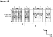
- FIG. 17 is a view showing a discovery signal and a PRACH resource composition based on a method M320 and a method M330 according to an exemplary embodiment.
- FIG. 17 as the exemplary embodiment of the method M320 illustrates a case in which the time offsets ⁇ T G,m ⁇ between the discovery signal block and the PRACH block are all the same. That is, the time domain distance between the m-th discovery signal block and the m-th PRACH block is T G .
- the time duration of each discovery signal block and the time duration of each PRACH block may be designed to be the same as T B .
- ⁇ Ts,m ⁇ and ⁇ T R,m ⁇ may not be defined in the technical specification, but the base station may arbitrarily determine the ⁇ Ts,m ⁇ and ⁇ T R,m ⁇ values. This is referred to as a method M331.
- the base station may determine the time distance between the m-th discovery signal block and the (m+1)-th discovery signal block based on traffic conditions. Accordingly, the base station may dynamically adjust a DL part and a UL part.
- the base station may arbitrarily determine the time distance between the m-th PRACH block and the (m+1)-th PRACH block.
- the time distance between the m-th discovery signal block and the (m+1)-th discovery signal block may be generally expressed as an integer number of OFDM symbols. If it is assumed that the number of OFDM symbols constituting a discovery signal block is N DS , the time distance between the m-th discovery signal block and the (m+1)-th discovery signal block may be an integer multiple of N DS .
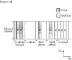
- FIG. 18 is a view showing a discovery signal and a PRACH resource composition based on a method M321 and a method M331 according to an exemplary embodiment.
- FIG. 18 as the exemplary embodiment of the method M331 illustrates a case in which ⁇ Ts,m ⁇ has different values according to m and ⁇ T R,m ⁇ is 0 for all m. That is, the time domain distance between the m-th discovery signal block and the (m+1)-th discovery signal block has different values according to m. The time domain distance between the m-th PRACH block and the (m+1)-th PRACH block is 0 regardless of m.
- FIG. 18 as an exemplary embodiment of the method M321 illustrates a case in which ⁇ T G,m ⁇ may have the different values according to m. That is, the time domain distance between the m-th discovery signal block and the m-th PRACH block has the different values according to m.
- the base station may flexibly operate the entire resource. For example, as illustrated in FIG. 18 , in a case of the traffic condition in which the downlink transmission and the uplink transmission must be quickly crossed into the subframe unit (for example, the DL subframe->the UL subframe->the special subframe->the special subframe->the UL subframe), as the base station disperses and allocates the discovery signal block and the PRACH block at the appropriate positions within one periodicity, the resource may be efficiently managed.
- the subframe unit for example, the DL subframe->the UL subframe->the special subframe->the special subframe->the UL subframe
- the method M331 is more advantageous than the method M330 in terms of forward compatibility.
- ⁇ T G,m ⁇ , ⁇ Ts,m ⁇ , and/or ⁇ T R,m ⁇ may have the fixed value for all periodicities of the discovery signal occasion or may have different values for each periodicity.
- RRM measurement accuracy of the terminal may decrease. Accordingly, although the base station arbitrarily determines the parameters (for example, T G,m , Ts,m, and T R,m ), changing the resource position over different periodicities by the base station may be limited.
- the parameter (for example, T G,m , Ts,m, T R,m , etc.) may have the same value for every periodicity of the discovery signal occasion. That is, the parameter (for example, T G,m , Ts,m, T R,m , etc.) may be applied as the same value for every periodicity of the discovery signal occasion.
- a plurality of PRACH formats may be used.
- the random access coverage and the access collision probability between terminals are improved.
- the plurality of PRACH formats used in the LTE have the same bandwidth, however, the plurality of PRACH formats have different time domain resource lengths from each other according to the numerology or the repetition of the preamble sequence.
- the plurality of PRACH formats are necessary.
- the short random access preamble may be required.
- the M PRACH resources exist and the terminal tries the access in one PRACH resource among the M PRACH resources, the probability of the access collision further decreases in each PRACH resource.
- the coverage is wide and the access collision probability increases, a long random access preamble or repeated transmission may be required.
- the base station may transmit the PRACH format to the terminal through the discovery signal. This is referred to as a method M340.
- the terminal may generate the random access preamble according to the obtained PRACH format through the discovery signal reception and may transmit the random access preamble on the PRACH resource.
- the PRACH format or the PRACH resource configuration information may be transmitted through the PBCH as a system information rather than through the synchronization signal or the BRS.
- the base station may transmit at least one among a plurality of PRACH formats to the terminal through the PBCH included in the discovery signal block.
- the above-described discovery signal, the PRACH resource configuration method, and the initial access procedures may be applied for any numerology.
- the carrier consists of a plurality of numerologies, like the case of the above-described synchronization signal, the plurality of numerologies may share the common discovery signal and PRACH.
- the method M221 or the method M222 may be applied for the numerology of the discovery signal.
- the discovery signal and the PRACH may be defined for each numerology within one carrier.
- the method M231, the method M232, or the method M233 may be applied.
- the numerology of the PRACH may be the same as the numerology of the discovery signal, or a separate numerology for the PRACH may be used.
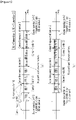
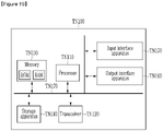
- FIG. 19 is a view showing a computing apparatus according to an exemplary embodiment.
- a computing apparatus TN100 of FIG. 19 may be the base station or the terminal described in the present specification. Also, the computing apparatus TN100 of FIG. 19 may be a wireless apparatus, a communication node, a transmitter, or a receiver.
- the computing apparatus TN100 includes at least one processor TN110, a transceiver TN120 connected to a network and performing the communication, and a memory TN130. Also, the computing apparatus TN100 may further include a storage apparatus TN140, an input interface apparatus TN150, an output interface apparatus TN160, etc. The constituent elements included in the computing apparatus TN100 are connected to each other by a bus TN170 to perform the communication with each other.
- the processor TN110 may execute a program command stored in at least one of the memory TN130 and the storage apparatus TN140.
- the processor TN110 may mean a central processing unit (CPU), a graphics processing unit (GPU), or a dedicated processor performing the methods according to an exemplary embodiment.
- the processor TN110 may be configured to realize the procedure, the function, and the methods that are described in relation to an exemplary embodiment.
- the processor TN110 may control each constituent element of the computing apparatus TN100.
- Each of the memory TN130 and the storage apparatus TN140 may store various information related to the operation of the processor TN110.
- Each of the memory TN130 and the storage apparatus TN140 may be composed of at least one of a volatile storage medium and a non-volatile storage medium.
- the memory TN130 may be composed of at least one of a read-only memory (ROM) and a random access memory (RAM).
- the transceiver TN120 may transmit and receive a wire signal or a wireless signal. Also, the computing apparatus TN100 may have a single antenna or a multi-antenna.
- the exemplary embodiments are not only embodied by the above-mentioned method and apparatus.
- the above-mentioned exemplary embodiments may be embodied by a program performing functions that correspond to the configuration of the exemplary embodiments, or a recording medium on which the program is recorded.
- These embodiments can be easily devised from the description of the above-mentioned exemplary embodiments by those skilled in the art to which the present invention pertains.
Description
- The present invention relates to methods for transmitting/receiving discovery signals.
- A wireless communication system supports a frame structure according to the technical specification. For example, a 3GPP (3rd Generation Partnership Project) LTE (Long Term Evolution) system supports frame structures of three types. The frame structures of three types include a
type 1 frame structure applicable to FDD (frequency division duplex), atype 2 frame structure applicable to TDD (time division duplex), and atype 3 frame structure for a transmission of a unlicensed frequency band. - In a wireless communication system such as the LTE system, a TTI (transmission time interval) means a basic time unit with which an encoded data packet is transmitted through a physical layer signal.
- A TTI of the LTE system is composed of one subframe. That is, a time domain length of a PRB (physical RB (resource block)) pair as a minimum unit of a resource allocation is 1 ms. To support the transmission of the 1 ms TTI unit, a physical signal and a channel are mainly defined by a subframe unit. For example, a CRS (cell-specific reference signal) may be permanently transmitted to every subframe, and a PDCCH (physical downlink control channel), a PDSCH (physical downlink shared channel), a PUCCH (physical uplink control channel), and a PUSCH (physical uplink shared channel) may be transmitted for each subframe. In contrast, a PSS (primary synchronization signal) and an SSS (secondary synchronization signal) exist for every fifth subframe, and a PBCH (physical broadcast channel) exists for every tenth subframe.
- ZTE: "Considerations on Channel Raster for NB-IoT", 3GPP DRAFT; R1-160051 CHANNEL RASTER, 3RD GENERATION PARTNERSHIP PROJECT (3GPP), MOBILE COMPETENCE CENTRE; 650, ROUTE DES LUCIOLES; F-06921 SOPHIA-ANTIPOLIS CEDEX; FRANCE, vol. RAN WG1, no. Budapest, HU; 11 January 2016, describes considerations on channel raster for NB-IoT. A channel raster of 100 kHz can be reused. It is proposed that for narrowband carrying NB-PSS/NB-SSS, a 100 kHz channel raster should exactly hit the centre subcarrier of NB-PSS/NB-SSS and the centre subcarrier is the 6th or 7th subcarrier of the narrowband including consecutive 12 subcarriers.
- Meanwhile, in the wireless communication system, a technique for transmitting/receiving the signal for a heterogeneous frame structure based on a plurality of numerologies is required.
- The present invention provides a method for transmitting discovery signals, performed by a base station operating a cell as described in
claim 1 and a method for receiving discovery signals, performed by a terminal as described by claim 6. Further embodiments of the invention are described in the dependent claims. -
-
FIG. 1 is a view showing atype 1 frame structure of an LTE system. -
FIG. 2 is a view showing atype 2 frame structure of an LTE system. -
FIG. 3 is a view showing a carrier raster and a carrier allocation based on a method M101 or a method M102 according to an exemplary embodiment. -
FIG. 4 is a view showing a case in which a plurality of numerologies are used in a common frequency band. -
FIG. 5 is a view showing a carrier raster and a carrier allocation based on a method M112 or a method M113 according to an exemplary embodiment. -
FIG. 6 is a view showing a synchronization signal resource region based on a method M201 according to an exemplary embodiment. -
FIG. 7 is a view showing a numerology of a synchronization signal and a resource region of a synchronization signal based on a method M202 according to an exemplary embodiment. -
FIG. 8 is a view showing a numerology of a synchronization signal and a resource region of a synchronization signal based on a method M203 according to an exemplary embodiment. -
FIG. 9 is a view showing a numerology of a synchronization signal and a resource region of a synchronization signal based on a method M210 according to an exemplary embodiment. -
FIG. 10 is a view showing a numerology of a synchronization signal and a resource region of a synchronization signal for a carrier composed of a plurality of numerologies according to an exemplary embodiment. -
FIG. 11 is a view showing a constituent element of a discovery signal according to an exemplary embodiment. -
FIG. 12 is a view showing a resource configuration of a discovery signal occasion based on a method M300 according to an exemplary embodiment. -
FIG. 13 is a view showing a resource composition of a discovery signal occasion based on a method M310 according to an exemplary embodiment. -
FIG. 14 is a view showing a case in which a TDM is applied between signal blocks in a method M300 or a method M310 according to an exemplary embodiment. -
FIG. 15 is a view showing a case in which a discovery signal occasion is transmitted in a discovery signal measurement window according to an exemplary embodiment. -
FIG. 16 is a view showing a discovery signal and a PRACH resource composition based on a method M310 according to an exemplary embodiment. -
FIG. 17 is a view showing a discovery signal and a PRACH resource composition based on a method M320 and a method M330 according to an exemplary embodiment. -
FIG. 18 is a view showing a discovery signal and a PRACH resource composition based on a method M321 and a method M331 according to an exemplary embodiment. -
FIG. 19 is a view showing a computing apparatus according to an exemplary embodiment. - As those skilled in the art would realize, the described embodiments may be modified in various different ways.
- Accordingly, the drawings and description are to be regarded as illustrative in nature and not restrictive. Like reference numerals designate like elements throughout the present specification.
- In the present specification, redundant description of the same constituent elements is omitted.
- Also, in the present specification, it is to be understood that when one component is referred to as being "connected" or "coupled" to another component, it may be connected or coupled directly to another component or be connected or coupled to another component with the other component intervening therebetween. On the other hand, in the present specification, it is to be understood that when one component is referred to as being "connected or coupled directly" to another component, it may be connected or coupled to another component without the other component intervening therebetween.
- It is also to be understood that the terminology used herein is only for the purpose of describing particular embodiments, and is not intended to be limiting of the invention.
- Singular forms are to include plural forms unless the context clearly indicates otherwise.
- It will be further understood that terms "comprises" or "have" used in the present specification specify the presence of stated features, numerals, steps, operations, components, parts, or a combination thereof, but do not preclude the presence or addition of one or more other features, numerals, steps, operations, components, parts, or a combination thereof.
- Also, as used herein, the term "and/or" includes any plurality of combinations of items or any of a plurality of listed items. In the present specification, 'A or B' may include 'A', 'B', or 'A and B'.
- In the present specification, a terminal may indicate a mobile terminal, a mobile station, an advanced mobile station, a high reliability mobile station, a subscriber station, a portable subscriber station, an access terminal, user equipment, and the like, or may include whole or partial functions of the mobile terminal, the mobile station, the advanced mobile station, the high reliability mobile station, the subscriber station, the portable subscriber station, the access terminal, the user equipment, and the like.
- Also, in the present specification, a base station (BS) may indicate an advanced base station, a high reliability base station (HR-BS), a node B, an evolved node B (eNodeB), an access point, a radio access station, a base transceiver station, a mobile multihop relay (MMR)-BS, a relay station executing a base station function, a high reliability relay station executing a base station function, a repeater, a macro base station, a small base station, and the like, or may include whole or partial functions of the advanced base station, the HR-BS, the nodeB, the eNodeB, the access point, the radio access station, the transceiver base station, the MMR-BS, the relay station, the high reliability relay station, the repeater, the macro base station, the small base station, and the like.
-
FIG. 1 is a view showing atype 1 frame structure of an LTE system. - One radio frame has 10 ms (=307200TS) length and consists of ten subframes. Here, Ts is a sampling time and has a value of Ts=1/(15 kHz*2048). Each subframe has the length of 1 ms, and one subframe consists of two slots of 0.5 ms length. One slot consists of seven time domain symbols (for example, an OFDM (orthogonal frequency division multiplexing) symbol) in a case of a normal CP (cyclic prefix), and consists of six time domain symbols (for example, the OFDM symbol) in a case of an extended CP. In the present specification, the time domain symbol may be the OFDM symbol, or an SC (single carrier)-FDMA (frequency division multiple access) symbol. However, this is merely an example, and an exemplary embodiment may be applied in a case in which the time domain symbol is the OFDM symbol or a different symbol from the SC-FDMA symbol.
-
FIG. 2 is a view showing atype 2 frame structure of an LTE system. - A relationship between the radio frame, the subframe, and the slot and each length thereof are the same as the case of the
type 1 frame structure. As a difference between thetype 2 frame structure and thetype 1 frame structure, in thetype 2 frame structure, one radio frame consists of a downlink (DL) subframe, an uplink (UL) subframe, and a special subframe. - The special subframe exists between the downlink subframe and the uplink subframe, and includes a DwPTS (downlink pilot time slot), a GP (guard period), and an UpPTS (uplink pilot time slot).
- One radio frame includes two special subframes in a case in which a downlink-uplink switching periodicity is 5 ms, and includes one special subframe in a case in which the downlink-uplink switching periodicity is 10 ms. In detail,
FIG. 2 shows a case in which the downlink-uplink switching periodicity is 5 ms, andsubframe 1 and subframe 6 are the special subframes. - The DwPTS is used for cell search, synchronization, or channel estimation. The GP is a period for removing an interference generated in the uplink of the base station due to a multipath delay difference of the terminals. In the UpPTS period, the transmission of the PRACH (physical random access channel) or the SRS (sounding reference signal) is possible. The wireless communication system according to an exemplary embodiment may be applied to various wireless communication networks. For example, the wireless communication system may be applied to a current wireless access technology (RAT: radio access technology)-based wireless communication network, or the 5G and beyond 5G wireless communication networks. The 3GPP develops a new RAT-based 5G technical specification satisfying IMT(International Mobile Telecommunications)-2020 requirements, and this new RAT is referred to as NR (new radio). In the present specification, for convenience of description, the NR-based wireless communication system is described as an example. However, it is merely an example, the present invention is not limited thereto, and the present invention may be applied to various wireless communication systems.
- As one among differences between the NR and a conventional 3GPP system (for example, CDMA (code division multiple access), LTE, etc.), NR uses a wide range of frequency bands in order to increase the transmission capacity. Related to this, the WRC (World Radiocommunication Conference)-15 hosted by the ITU (International Telecommunication Union) determined a WRC-19 agenda, and the WRC-19 agenda includes consideration of a 24.25-86 GHz band as the candidate frequency band for the IMT-2020. The 3GPP considers the frequency band from 1 GHz or less to 100 GHz as the NR candidate frequency band.
- As a waveform technology for the NR, OFDM (orthogonal frequency division multiplexing), filtered OFDM, GFDM (generalized frequency division multiplexing), FBMC (filter bank multicarrier), UFMC (universal filtered multicarrier), etc. are being considered as the candidate technology.
- In the present specification, as the waveform technology for the wireless access, a case using a CP-based OFDM (CP-OFDM) is assumed. However, this is merely for convenience of explanation, the present invention is not limited to the CP-OFDM, and it can be applied to various waveform technologies. In general, in a category of the CP-OFDM technology, the CP-OFDM technology applied with windowing and/or filtering or spread spectrum OFDM technology (for example, DFT-spread OFDM) is included.
- Table 1 below represents an example of an OFDM system parameter configuration for the NR system.
- In Table 1 (an example of the OFDM system parameter configuration), the frequency band of 700 MHz-100 GHz is divided into three regions (i.e., a low frequency band (-6 GHz), a high frequency band (3-40 GHz), and a super high frequency band (30-100 GHz)), and different OFDM numerologies from each other are applied to each frequency band. In this case, one of main factors determining subcarrier spacing of the OFDM system is a carrier frequency offset (CFO) suffered by a receiving terminal. The carrier frequency offset (CFO) has a characteristic that it increases in proportion to the operation frequency due to a Doppler effect and a phase drift. Accordingly, to block performance degradation by the carrier frequency offset, the subcarrier spacing must be increased in proportion to the operation frequency. In contrast, if the subcarrier spacing is very large, there is a drawback that a CP overhead increases. Accordingly, the subcarrier spacing must be defined as an appropriate value considering the channel and the RF (radio frequency) characteristic for each frequency band.
- The subcarrier spacing of SETs A, B, and C of Table 1 is 16.875 kHz, 67.5 kHz, and 270 kHz, respectively, which is approximately in proportion to a target operation frequency, and is configured to make a difference of four times.
(Table 1) Set A Set B Set C Carrier frequency Low freq. (-6 GHz) High freq. (3-40 GHz) Very high freq. (30-100 GHz) Subcarrier spacing 16.875 kHz 67.5 kHz 270 kHz CP overhead 5.2 % 5.2 % 5.2 % Number of OFDM symbols per 1 ms 16 64 256 - Meanwhile, the values of the subcarrier spacing used in Table 1 are merely exemplary, and the subcarrier spacing may be designed with as many other values as necessary. For example, 15 kHz of the conventional LTE subcarrier spacing is used as a base numerology, and the subcarrier spacing (for example, 30 kHz, 60 kHz, 120 kHz, 240 kHz, etc.) scaled with multiplication by power of two based on this may be used for the numerology scaling. This is illustrated in Table 2 (as an example of the OFDM system parameter configuration). To configure the subcarrier spacing to make the difference by multiplication by power of two between the subcarrier spacing of the heterogeneous numerologies may be advantageous to the operation (for example, carrier aggregation, dual connectivity, or multiplexing of the heterogeneous numerologies within one carrier) between the heterogeneous numerologies.
(Table 2) Set A Set B Set C Set D Set E Subcarrier spacing 15 kHz 30 kHz 60 kHz 120 kHz 240 kHz CP overhead 6.7 % 6.7 % 6.7 % 6.7 % 6.7 % Number of OFDM symbols per 1 ms 14 28 56 112 224 - One numerology may be basically used for one cell (or one carrier), and may be used for a special time-frequency resource within one carrier. The heterogeneous numerology may be used for the different operation frequency bands from each other as illustrated in Table 1, and may be used to support different service types from each other in the same frequency band. As an example of the latter, the SET A of Table 1 can be used for the eMBB (enhanced mobile broadband) service of the 6 GHz band or less, and the SET B or the SET C of Table 1 can be used for the URLLC (ultra-reliable low latency communication) service of the 6 GHz band or less. Meanwhile, to support the mMTC or the MBMS (multimedia broadcast multicast services) service, the numerology having the smaller subcarrier spacing than that of the subcarrier spacing of the basic numerology may be used. For this, in a case in which the subcarrier spacing of the basic numerology is 15 kHz, the subcarrier spacing of 7.5 kHz or 3.75 kHz may be considered.
- Hereinafter, the method and the apparatus for transmitting the signal for the heterogeneous frame structure based on the plurality of numerologies in the wireless communication system will be described.
- To discover a cell (or a carrier) in initial cell search process, a terminal must be able to detect the synchronization signal of the corresponding cell for all candidate frequencies on the carrier raster in the frequency band to which the corresponding cell belongs. The synchronization signal may be transmitted with reference to one frequency among the candidate frequencies. For example, in the LTE system, the carrier raster spacing is 100 kHz, and the DC (direct current) subcarrier as the center of the subcarriers to which the synchronization signal is transmitted is aligned on a specific graduation point of the carrier raster.
- When the detection of the synchronization signal is successful, the terminal may derive the center frequency position of the cell (the carrier) from the frequency value of the corresponding carrier raster graduation point. In the case of the LTE system, since the center frequency of the synchronization signal and the center frequency of the cell (or the carrier) are the same, the terminal may obtain the center frequency of the cell (or the carrier) without help of the base station.
- On the other hand, to increase the frequency resource utilization efficiency, the new carrier raster may be designed. Next, the carrier raster may mean a group of the candidate reference frequencies of the synchronization signal or may mean a group of the candidate center frequencies of the cell (or the carrier). The former and the latter can generally be separated from one another.
- In a case of an intra-band contiguous carrier aggregation, to minimize the idle band inevitably generated between the carriers, the frequency spacing of the carrier raster may be determined as an integer multiple of the subcarrier spacing. This is referred to as a method M100.
- Also, when it is assumed that one resource block consists of N resource elements in the frequency domain, the raster spacing may be determined as an integer multiple of the multiplication of the subcarrier spacing and N. This is referred to as a method M101. For example, the spacing of the carrier raster for a frequency band using the numerology having a subcarrier spacing of 15 kHz may be a multiple of 15 kHz by the method M100. In this case, if N=12 is assumed, the raster spacing may be a multiple of 180 kHz or may be 180 kHz itself by the method M101.
-
FIG. 3 is a view showing a carrier raster and carrier allocation based on a method M101 or a method M102 according to an exemplary embodiment. - In detail, (a) and (b) of
FIG. 3 illustrate a case in which the carrier raster spacing is the same as the bandwidth occupied by one resource block as an exemplary embodiment of the method M101. - As illustrated in (a) of
FIG. 3 , when two adjacent carriers (Carrier 1 and Carrier 2) both have an even number (for example, four) of resource blocks (for example,RB 0,RB 1,RB 2, and RB 3), the method M101 may perform the carrier allocation as there is no idle band (or band gap) between the carriers (Carrier 1, Carrier 2). This may be applied the same or a similar way when both of two adjacent carriers have an odd number of resource blocks. - However, as illustrated in (b) of
FIG. 3 , when one carrier (Carrier 1) has an even number (for example, four) of resource blocks (for example, RB 0-RB 3) and the other carrier (Carrier 2) adjacent thereto has an odd number (for example, three) of resource blocks (for example, RB 0-RB 2), the idle band (or the band gap) between the carriers (Carrier 1, Carrier 2) may be inevitably generated. - To solve the above-described problem, the raster spacing may be determined as the multiplication of the subcarrier spacing and N/2, that is, half of the bandwidth occupied by one resource block. This is referred to as a method M102. For example, when the subcarrier spacing is 15 kHz and N=12, the raster search spacing may be 90 kHz. The exemplary embodiment of the method M102 is illustrated in (c) of
FIG. 3 . - As illustrated in (c) of
FIG. 3 , when one carrier (Carrier 1) has the even number (for example, four) of resource blocks (for example, RB 0-RB 3) and the other carrier (Carrier 2) has the odd number (for example, three) of resource blocks (for example, RB 0-RB 2), the method M102 may perform the carrier allocation as there is no idle band (or the band gap) between the carriers (Carrier 1, Carrier 2). - For the method M101 and the method M102, the center frequency position design is important. If, like the LTE downlink, when one subcarrier of the center frequency is defined as the DC (direct current) subcarrier and the DC subcarrier is excluded from the composition of resource blocks, even if the method M101 or the method M102 is used, the idle band may be inevitably generated between the carriers due to the frequency part occupied by the DC subcarrier. In contrast, like the LTE uplink, when the center frequency is defined as the middle between two subcarriers and the resource block is composed by using all subcarriers (however, the subcarrier of a guard band is excluded), the above-described effect of the method M101 or the method M102 may be obtained. This may also be established for the method described later.
- On the other hand, as described above, a plurality of numerologies may be used in one frequency band. Here, one frequency band may mean a specific frequency range, and the specific frequency range may be wide or narrow. For example, a specific frequency range may be the bandwidth of one carrier, may be one frequency band having a bandwidth of several to several hundreds of MHz, or may be a wider region than that.
-
FIG. 4 is a view showing a case in which a plurality of numerologies are used in a common frequency band. In detail,FIG. 4 illustrates a case in which three heterogeneous numerologies (Numerology 1,Numerology 2, and Numerology 3) are used in a common frequency band. - In
FIG. 4 , it is assumed that the subcarrier spacing ofNumerology 2 is larger than the subcarrier spacing ofNumerology 1, and the subcarrier spacing ofNumerology 3 is larger than the subcarrier spacing ofNumerology 2. This is expressed by the difference between the time domain of the resource grid lengths (the difference between the OFDM symbol lengths) or the difference between the frequency domain of the resource grid lengths inFIG. 4 . For example, when the subcarrier spacing ofNumerology 1 is 15 kHz, the subcarrier spacing ofNumerology 2 andNumerology 3 may be 30 kHz and 60 kHz, respectively. - A plurality of heterogeneous numerologies may be respectively used for the different carriers, and may be used together in one carrier. In detail,
FIG. 4 illustrates a case in whichNumerology 1 andNumerology 2 coexist within one carrier andNumerology 3 constitutes one carrier by itself. - On the other hand, when a plurality of numerologies are used within one frequency band, the carrier raster may be defined for each numerology. This is referred to as a method M110. In this case, to distinguish the graduation of the carrier raster for each numerology, an offset of the carrier raster graduation may be determined. This is referred to as a method M111.
- For example, the carrier raster of
Numerology 1 can have a 0 kHz offset and a 100 kHz spacing, and the carrier raster ofNumerology 2 can have a 50 kHz offset and a 200 kHz spacing. That is, the frequency such as 100 kHz, 200 kHz, 300 kHz, etc. may be the center frequency candidates ofNumerology 1, and the frequency such as 50 kHz, 250 kHz, 450 kHz, etc. may be the center frequency candidates ofNumerology 2. In this case, for example, when the terminal initially searches only the cell (or the carrier) havingNumerology 2, the terminal only searches the candidate center frequencies having a 50 kHz offset and a 200 kHz spacing. In this case, the terminal may assume thatNumerology 2 is applied to the entire or some region of the cell (or the carrier) of which the search is successful. - Meanwhile, in the case of the method M110, the graduations of the carrier raster for the numerologies may be defined to have an inclusion relationship to each other. This is referred to as a method M112.
- For example, the carrier raster of
Numerology 1 may have a 0 kHz offset and a 100 kHz spacing, and the carrier raster ofNumerology 2 may have a 0 kHz offset and a 200 kHz spacing. In this case, the frequency such as 100 kHz, 300 kHz, 500 kHz, etc. may be the center frequency candidates ofNumerology 1, and the frequency such as 200 kHz, 400 kHz, 600 kHz, etc. may be the center frequency candidates ofNumerology 1 andNumerology 2. - When the terminal initially searches the cell (or the carrier) for the plurality of numerologies within any frequency band, the method M112 may reduce a number of the carrier raster graduation points to be searched by the terminal compared with the method M111. In this case, in the illustrations, when the terminal detects the cell in the frequency such as 200 kHz, 400 kHz, and 600 kHz, a method to distinguish whether the cell detected by the terminal is based on
Numerology 1 orNumerology 2 is required. This will be described in detail in 'synchronization signal design' part later. - Meanwhile, in the case of the method M110, the method M111, or the method M112, the frequency spacing of the carrier raster for the numerology may be determined to be proportional to the subcarrier spacing of each numerology. This is referred to as a method M113. For example, when
Numerology 1 andNumerology 2 have the subcarrier spacing of 15 kHz and 30 kHz, the carrier raster spacing ofNumerology 2 may be two times the carrier raster spacing ofNumerology 1. In this case, as a method defining the carrier raster spacing, the method M101 and the method M102 may be used. - Meanwhile, when NRE as the number of resource elements of one resource block in the frequency domain is the same for all numerologies, the method M113 may help to minimize the idle band between the carriers within the same band.
-
FIG. 5 is a view showing a carrier raster and a carrier allocation based on a method M112 or a method M113 according to an exemplary embodiment. In detail, inFIG. 5 , it is assumed that the subcarrier spacing of Numerology 2 (N2) is two times the subcarrier spacing of Numerology 1 (N1). - The carrier raster for Numerology 1 (N1) includes the carrier raster for Numerology 2 (N2) by the method M112, and the carrier raster spacing for Numerology 2 (N2) is two times the carrier raster spacing for Numerology 1 (N1) by the method M113.
- In this case, if it is assumed that NRE (the number of resource elements of one resource block in the frequency domain) is the same for Numerology 1 (N1) and Numerology 2 (N2), as illustrated in
FIG. 5 , the resource block of the carrier 2 (Carrier 2) occupies the bandwidth that is wider than the resource block of the carrier 1 (Carrier 1) by two times. - In
FIG. 5 , it is assumed that the method M101 is used to define the raster spacing. That is, the raster spacing of Numerology 1 (N1) is the same as the bandwidth occupied by one resource block of thecarrier 1, and the raster spacing of Numerology 2 (N2) is the same as the bandwidth occupied by one resource block of thecarrier 2. - As an effect for this, regardless of whether the number of the resource blocks of the
carrier 2 is even (for example, (a) ofFIG. 5 ) or odd (for example, (b) ofFIG. 5 ), when thecarrier 1 has the even number of resource blocks (RB0-RB3), the carrier allocation may be performed as there is no idle band (or guard band) between the carriers (Carrier 1, Carrier 2). - If the method M102 is used instead of the method M101, even if the
carrier 1 has the odd number of resource blocks, the carrier allocation may also be performed as there is no idle band between the carriers. Instead, as the carrier raster spacing is reduced, the cell search complexity may increase. - Meanwhile, one carrier raster may be commonly defined for the plurality of numerologies. This is referred to as a method M120. For example, the carrier raster defined with reference to the numerology of the smallest subcarrier spacing within one frequency band may be used for the plurality of numerologies. In this case, because the terminal may need to perform the cell search for the plurality of numerologies for all carrier raster graduation points, the method M120 may increase the complexity compared with the method M112.
- Meanwhile, the carrier raster may be defined for each frequency band. For example, it may be defined so that only numerology(ies) having the subcarrier spacing that is relatively large is used in the high frequency band. In this case, the carrier raster for the high frequency band may have the wider spacing than that of the carrier raster for the low frequency band.
- According to the above description, the terminal may need to assume the plurality of numerologies for one carrier raster graduation and the synchronization signal or the cell (or the carrier) thereof in the initial cell search process.
- Hereinafter, a method of transmitting the synchronization signal for the initial cell search of the terminal through the base station in the case in which the plurality of numerologies are used within the common frequency range will be described.
- Firstly, a case of the carrier configured of the single numerology is considered. In this case, the method M200 and the method M210 exist according to the relationship between the numerology of the synchronization signal and the numerology of the carrier.
- The method M200 is a method in which the numerology applied to the synchronization signal follows the numerology of the carrier to which the synchronization signal belongs.
- According to the method M200, because there is no interference between the synchronization signal and the signal of the adjacent frequency domain, the method M200 has a merit that it is not necessary to additionally set the guard band.
- The terminal may attempt the detection of the synchronization signal by each numerology for the plurality of numerologies candidates. When the terminal has the successfully detected synchronization signal, the terminal may consider the numerology of the detected synchronization signal as the numerology of the carrier to which the detected synchronization signal belongs.
- When the synchronization signal detection is performed in the time domain, the process thereof may be performed through the sampling, the filtering, and a correlator. Here, the filtering may be low-pass filtering when the synchronization signal is disposed to be symmetric with reference of the center frequency like the LTE. The correlator may be implemented with an auto-correlator, a self-correlator, or a cross-correlator according to the characteristic of the synchronization signal sequence.
- As a sequence of the synchronization signal, a Zadoff-Chu sequence, a Gold sequence, and the like may be used. When the resource region of the synchronization signal is configured with a plurality of OFDM symbols, the sequence of the synchronization signal may be defined for each OFDM symbol and may be a long sequence occupying the plurality of OFDM symbols.
- Hereinafter, the method M201 and the method M202 will be described as detailed methods of the method M200.
- The method M201 is the method in which the time-frequency resource element configuration of the synchronization signal resource region is the same for the plurality of numerologies. That is, the method M201 is the method in which the resource element mapping of the synchronization signal is the same regardless of the numerology.
-
FIG. 6 is a view showing a synchronization signal resource region based on a method M201 according to an exemplary embodiment. - In detail,
FIG. 6 illustrates a case in which the method M201 is applied to two numerologies (Numerology 1 and Numerology 2) that are different from each other. InFIG. 6 , it is assumed that the sequence length of the synchronization signal is 6 and the subcarrier spacing ofNumerology 2 is larger than the subcarrier spacing ofNumerology 1. - According to the method M201, for both of
Numerology 1 andNumerology 2, the resource region of the synchronization signal occupies one resource element (i.e., one OFDM symbol) in the time domain and occupies six continuous resource elements in the frequency domain. - FBW,1 represents the bandwidth occupied by the synchronization signal applied with
Numerology 1, and FBW,2 represents the bandwidth occupied by the synchronization signal applied withNumerology 2. FBW,2 is larger than FBW,1. - In the case in which the method M201 is used, because the terminal needs to apply the different sampling, the different filtering, and/or the different correlator for each numerology, the complexity and the delay time for the initial cell search of the terminal may increase. Also, when the subcarrier spacing of the numerology is large, because the bandwidth used to the initial cell search increases, a required sampling rate may increase. For example, when the subcarrier spacing of the carrier is 60 kHz, the high sampling rate of four times may be required compared with the case in which the subcarrier spacing is 15 kHz. In contrast, since the period in which the synchronization signal is transmitted decreases as the subcarrier spacing increase, the method M201 may be advantageous to beam sweeping-based transmission in the high frequency band.
- In the present specification, the resource region of the synchronization signal basically means a group of the resource elements in which the synchronization signal is mapped. Meanwhile, when the band pass filtering for the synchronization signal detection of the terminal is non-ideal, the guard band may need to be inserted at both ends of the bandwidth of the synchronization signal. For example, in the LTE, five adjacent subcarriers existing at both ends of the bandwidth of the PSS and the SSS are defined as the guard band. In this case, the resource region of the synchronization signal may mean the region including both the resource region where the synchronization signal is mapped and the guard band.
- The method M202 is a method defining the bandwidth so that the bandwidth occupied by the synchronization signal resource region is the same or similar regardless of the numerology.
-
FIG. 7 is a view showing a numerology of a synchronization signal and a resource region of a synchronization signal based on a method M202 according to an exemplary embodiment. - In detail,
FIG. 7 illustrates a case in which the method M202 is applied to two different numerologies (Numerology 1 and Numerology 2). InFIG. 7 , it is assumed that the subcarrier spacing (2*K) forNumerology 2 is two times the subcarrier spacing (K) forNumerology 1. That is, inFIG. 7 , it is assumed that the OFDM symbol length L forNumerology 1 is two times the OFDM symbol length L/2 forNumerology 2. - In
FIG. 7 , it is assumed that the number of resource elements constituting the resource region of the synchronization signal is 8 in the case ofNumerology 1 and 12 in the case ofNumerology 2. - According to the method M202, the resource region of the synchronization signal includes eight resource elements in the frequency domain and one resource element in the time domain in the case of
Numerology 1, and includes four resource elements in the frequency domain and three resource elements in the time domain in the case ofNumerology 2. In this case, FBW,1 and FBW,2 of the bandwidth of the synchronization signal resource region are the same (i.e., FBW,1=FBW,2=F). Accordingly, the method M202 has the merit that the terminal may apply the same filtering to the plurality of numerologies in the initial cell search process. Also, the method M202 may transmit the synchronization signal to the narrow bandwidth regardless of the subcarrier spacing of the numerology. In contrast, in the method M202, since the number of the OFDM symbols occupied by the synchronization signal resource region may be different for each numerology, the sequence design considering this and the coexistence design with the other signals and channels considering this are required. - In the method M202, the fact that the bandwidths of the synchronization signal resource region are similar regardless of the numerologies may mean that the bandwidths are sufficiently similar (for example, within a few subcarriers difference) in applying the common filtering to the plurality of numerologies through the terminal.
- Meanwhile, in the method M202, a method for performing the mapping may be considered so that the time duration is also the same or similar regardless of the numerology as well as the bandwidth of the synchronization signal resource region. This is referred to as a method M203.
-
FIG. 8 is a view showing a numerology of a synchronization signal and a resource region of a synchronization signal based on a method M203 according to an exemplary embodiment. - In detail, in
FIG. 8 , like the exemplary embodiment ofFIG. 7 , it is assumed that the subcarrier spacing (2*K) forNumerology 2 is two times the subcarrier spacing (K) forNumerology 1. That is, inFIG. 8 , it is assumed that the OFDM symbol length L forNumerology 1 is two times the OFDM symbol length L/2 forNumerology 2. - In
FIG. 8 , it is assumed that the number of resource elements constituting the synchronization signal resource region is 8 in both the case ofNumerology 1 and the case ofNumerology 2. - According to the method M203, the resource region of the synchronization signal includes eight resource elements in the frequency domain and one resource element in the time domain in the case of
Numerology 1, and includes four resource elements in the frequency domain and two resource elements in the time domain in the case ofNumerology 2. That is, the bandwidth FBW,1 occupied by the synchronization signal resource region forNumerology 1 and the bandwidth FBW,2 occupied by the synchronization signal resource region forNumerology 2 are the same, and the time duration T occupied by the synchronization signal resource region forNumerology 1 and the time duration T occupied by the synchronization signal resource region forNumerology 2 are the same. - Also, in the method M202 or the method M203, the frequency resource region may be the same for the plurality of numerologies as well as the frequency bandwidth of the synchronization signal resource region. For example, the synchronization signal may occupy the bandwidth of FBW,1 Hz or FBW,2 Hz at the center of the system bandwidth regardless of the numerology.
- The method M210 is a method in which the numerology applied to the synchronization signal is fixed regardless of the numerology of the carrier to which the synchronization signal belongs.
-
FIG. 9 is a view showing a numerology of a synchronization signal and a resource region of a synchronization signal based on a method M210 according to an exemplary embodiment. - In detail,
FIG. 9 illustrates a case in which the synchronization signal of the carrier applied withNumerology 1 and the synchronization signal of the carrier applied withNumerology 2 both followNumerology 1. For example, in the case ofNumerology 1, the resource region for the synchronization signal includes eight resource elements in the frequency domain and one resource element in the time domain. That is, the bandwidth F and the time duration T occupied by the synchronization signal resource region forNumerology 1 are the same as the bandwidth F and the time duration T occupied by the synchronization signal resource region forNumerology 2. - In
FIG. 9 , it is assumed that the subcarrier spacing (2*K) forNumerology 2 is two times the subcarrier spacing (K) forNumerology 1. That is, inFIG. 9 , it is assumed that the OFDM symbol length L forNumerology 1 is two times the OFDM symbol length L/2 forNumerology 2. - The method M210 may be applied within a specific frequency range.
- The method M210 may predetermine the numerology for the synchronization signal as one among the numerologies allowed within a specific frequency range. For example, the synchronization signal in the frequency band of 6 GHz or less may always be transmitted based on the numerology having the subcarrier spacing of 15 kHz.
- According to the method M210, the terminal may search the synchronization signal through a single numerology in the initial cell search process.
- However, since the numerology of the synchronization signal and the numerology of the carrier may be different, a separate method that is capable of determining which numerology the terminal applies to the carrier is required. The terminal may explicitly or implicitly acquire the numerology of the carrier through the synchronization signal reception. Also, the terminal may obtain the numerology of the carrier through the signal or the channel (for example, PBCH) received by the terminal after the synchronization signal. In this case, the signal or the channel received by the terminal after the synchronization signal follows the same numerology as the numerology of the synchronization signal. In the method M210, since the numerology of the signal and the channel adjacent to the synchronization signal in the frequency domain may be different from the numerology of the synchronization signal, an additional guard band may be inserted to both ends of the bandwidth of the synchronization signal.
- Next, a case of the carrier configured with a plurality of numerologies is considered.
- In one carrier, the plurality of numerologies may be multiplexed through the TDM (time division multiplexing), or may be multiplexed through the FDM (frequency division multiplexing) like the exemplary embodiment of
FIG. 4 . In this case, a method (hereinafter, 'method M220') in which a plurality of numerologies share one synchronization signal and a method (hereinafter, 'method M230') in which the synchronization signal is transmitted for each numerology may be used. - In the case in which the plurality of numerologies share one synchronization signal, like the method M200, the numerology of the synchronization signal may follow one among the plurality of numerologies within the carrier. This is referred to as a method M221. The method M221 will be described with reference to
FIG. 10 . -
FIG. 10 is a view showing a numerology of a synchronization signal and a resource region of a synchronization signal for a carrier composed of a plurality of numerologies according to an exemplary embodiment. -
FIG. 10 illustrates a case in which two numerologies (Numerology 1, Numerology 2) are applied in one carrier. - In
FIG. 10 , it is assumed that the subcarrier spacing forNumerology 2 is larger than the subcarrier spacing forNumerology 1. That is, inFIG. 10 , it is assumed that the OFDM symbol length forNumerology 1 is larger than the OFDM symbol length forNumerology 2. - As illustrated in
FIG. 10 , the synchronization signal resource region may be defined within the resource region to which the same numerology as the numerology (for example, Numerology 1) of the synchronization signal is applied. -
FIG. 10 illustrates the case in which the resource region for the synchronization signal includes six resource elements in the frequency domain and one resource element in the time domain. - The numerology of the synchronization signal may be used as the base numerology within one carrier. That is, the terminal accessed to the corresponding carrier may receive the signal by using the base numerology within the specific time-frequency resource region before separately configured with a numerology.
- When only one synchronization signal exists in the carrier consisting of the plurality of numerologies, the synchronization signal may be defined at the center of the carrier bandwidth (for example, to be symmetrical based on the center frequency). In this case, when the plurality of numerologies are multiplexed through the FDM, the terminal may at least assume the same numerology as the numerology of the synchronization signal for the center bandwidth occupied with the synchronization signal.
- As the resource region configuration method of the synchronization signal, the above-described methods (for example, the method M201, the method M202, the method M203, etc.) may be used.
- Meanwhile, when the plurality of numerologies share one synchronization signal, like the method M210, the numerology of the synchronization signal may follow a predetermined numerology regardless of the numerologies of the carrier. This is referred to as a method M222.
- When the synchronization signal is transmitted for each numerology within one carrier, the numerology of each synchronization signal may follow the numerology of the resource region in which the synchronization signal is defined. This is referred to as a method M231. The method M231 may be considered as the method M200 being applied within one carrier.
- In this case, the configuration of the synchronization signal resource region may follow the above-described method (for example, the method M201, the method M202, the method M203, etc.).
- Differently from the method M231, the numerology of all synchronization signals within one carrier may follow one among a plurality of numerologies constituting the carrier. This is referred to as a method M232.
- Also, the numerology of all synchronization signals within one carrier may follow a predetermined numerology regardless of the numerology of the carrier. This is referred to as a method M233.
- When the above-described methods are applied to a carrier consisting of a plurality of numerologies, a capability of the terminal may be considered.
- When a NR terminal is basically capable of receiving a plurality of numerologies, the method M220 may be used. A terminal supporting the eMBB and the URLLC may correspond to this. In this case, the terminal may use the different numerologies from each other for the synchronization signal reception and the data reception.
- In contrast, for the terminal without the capability of receiving the plurality of numerologies, the method M230 may be used. A low-cost terminal to support only a specific numerology for the mMTC transmission may correspond to this. In this case, the terminal uses the same numerology for the synchronization signal reception and the data reception.
- Within one carrier, the method M220 and the method M230 may be combined and used.
- In the above-described methods (for example, the method M200 to the method M233), transmission timing and the periodicity of the synchronization signal may be the same for a plurality of numerologies.
- Meanwhile, since the length of the subframe and the group of the subframe numbers may be different from each other for the heterogeneous frame structure having the different numerologies, the transmission timing and the periodicity of the synchronization signal may be expressed by different equations for each frame structure.
- When the transmission timing and the periodicity of the synchronization signal are the same, the initial cell search complexity of the terminal may be reduced.
- Meanwhile, in the above-described methods, the different signals (or the different channels) may be mapped to the resource region of the synchronization signal. That is, within the synchronization signal resource region, the synchronization signal and the signal (or the channel) other than the synchronization signal may coexist. For example, when the synchronization signal is mapped to the non-continuous resource elements in the frequency domain, the resource elements to which the synchronization signal is not mapped may be used for the transmission of the other signals (or the channels). The above-described synchronization signal may be limited to the usage searching the center frequency of the cell (or the carrier) in the initial cell search process of the terminal. In this case, in the frequency domain that does not support a standalone operation of the cell (or the carrier), the synchronization signal may not exist. Also, when the cell (or the carrier) is operated as an only secondary cell, the synchronization signal may not exist.
- Meanwhile, the above-described synchronization signal may also be used for synchronization acquisition, synchronization tracking, and/or cell ID acquisition of the terminal as well as the center frequency search.
- Also, the above-described synchronization signal may be used as a pilot for the channel estimation (or the data decoding).
- Particularly, when the synchronization signal is used for other uses as well as the center frequency search, the synchronization signal may be configured with a plurality of synchronization signals. For example, the synchronization signal may be configured with a first synchronization signal and a second synchronization signal. When the synchronization signal is configured with a plurality of synchronization signals, the above-described methods (for example, the method M200 to the method M210) may only be applied to some of synchronization signals (for example, the first synchronization signal). Also, the above-described methods (for example, the method M200 to the method M210) may be applied to the plurality of synchronization signals (for example, the first synchronization signal, the second synchronization signal). In this case, the synchronization signal resource region defined for the above-described methods (for example, the method M200 to the method M210) may include only some of synchronization signals in the former case and may include the plurality of synchronization signals in the latter case.
- Since the NR supports the wide range of frequency, the operation of the high frequency band and the operation of the low frequency band may be different from each other.
- In the high frequency band in which a path loss of the signal is large, transmit beamforming and/or receive beamforming may be applied. For a coverage extension of the cell or the terminal, a beamforming may also be applied to the common signal and the control channel as well as the data channel. In this case, when a beam having a small beamwidth is formed through a plurality of antennas, to cover the entire coverage of the cell or the sector, the signal may need to be received or transmitted several times through the beams having a plurality of different direction directivities. To transmit the signal applied with the beamforming through the different resources from each other in the time domain is referred to as beam sweeping.
- In contrast, in the low frequency band in which the path loss of the signal is relatively small, even if the common signal and the control channel are transmitted one time, the entire coverage of the cell or the sector may be covered.
- The initial access procedure of the NR must support all the above-different beam operations.
- Hereinafter, the resource composition and the transmission method for the signals for the initial access of the terminal will be described. A method (a band-agnostic or beam operation-agnostic method) that may be commonly used regardless of the frequency band or the beam operation will be described.
- For the initial access of the terminal, a downlink discovery signal and an uplink PRACH may be used.
- First, the downlink discovery signal will be described.
- The discovery signal may be the downlink signal for the cell search, system information acquisition, beam acquisition and tracking, and so on of the terminal, and may be periodically transmitted to the terminal. A discovery signal occasion may be defined.
-
FIG. 11 is a view showing a constituent element of a discovery signal according to an exemplary embodiment. - The discovery signal occasion may consist of the synchronization signal and the PBCH, as illustrated in (a) of
FIG. 11 . - The synchronization signal may be used for the time-frequency synchronization, the cell ID acquisition, etc., and the PBCH may be used to transmit system information (SI) that is essential for the initial access. A cell (or a base station) that does not support the initial access may not transmit the PBCH. That is, the discovery signal occasion may not include the PBCH.
- The synchronization signal may be composed of a plurality of synchronization signals. For example, the synchronization signal may consist of a primary synchronization signal (PSS) and a secondary synchronization signal (SSS).
- Also, as illustrated in (b) of
FIG. 11 or (c) ofFIG. 11 , the discovery signal occasion may consist of the synchronization signal, PBCH, and a beam reference signal (BRS). - The BRS may be used for beam or beam ID acquisition, RRM (radio resource management) measurement, and/or PBCH decoding. The TDM may be applied between the PBCH and the BRS. Also, for better PBCH decoding performance, as illustrated in (c) of
FIG. 11 , the PBCH and the BRS may coexist in a common region. - Also, the discovery signal occasion may include the reference signal for CSI (channel state information) measurement and reporting, that is, a CSI-RS (reference signal). The discovery signal occasion may also include a separate reference signal for the beam tracking. The CSI-RS and/or the beam tracking reference signal may be set to be terminal specific (UE-specific).
- When the discovery signal occasion is used for the initial cell search of the terminal, a transmission periodicity and an offset of the discovery signal occasion may be a fixed value that is predefined.
- It is assumed that M time-frequency resources exist for each of the synchronization signal, the PBCH, and/or the BRS within one discovery signal occasion periodicity. Here, M is a natural number. That is, the element signals included in the discovery signal occasion may respectively use the M resources. The M resources for each element signal have the same bandwidth and the same time duration (for example, the same number of OFDM symbols).
- In a case of M>1, the beam sweeping may be applied to each of the synchronization signal, the PBCH, and/or the BRS through the plurality of resources. In a case of M=1, a single beam may be transmitted or a plurality of beams may be transmitted through SDM (spatial division multiplexing) on the same resource.
- The discovery signal occasion may consist of a plurality of signal blocks. The resource occupied by one signal block is continuous in the time and frequency domains. That is, the resource occupied by one signal block may include time domain symbols that are continuous in the time domain. In this case, a method M300 and a method M310 may be considered according to the element signal constituting the signal blocks.
- The method M300 is a method in which the discovery signal occasion consists of the heterogeneous signal blocks. That is, the discovery signal occasion may consist of the synchronization signal block(s) and the PBCH block. In this case, when the BRS exists for the decoding of the PBCH, the BRS may be included in the PBCH block.
-
FIG. 12 is a view showing a resource configuration of a discovery signal occasion based on a method M300 according to an exemplary embodiment. - In detail,
FIG. 12 illustrates a case in which the discovery signal occasion consists of three heterogeneous signal blocks (a first signal block, a second signal block, and a third signal block). - The first signal block is the PSS block, and includes M PSS resources classified through the TDM. The second signal block is the SSS block and includes M SSS resources classified through the TDM. The third signal block is the PBCH block and includes M PBCH resources and/or M BRS resources classified through the TDM.
- As another example, the discovery signal occasion may be configured of two heterogeneous signal blocks (a first signal block and a second signal block). The first signal block is the PSS and the SSS block and includes the M PSS resources and the M SSS resources classified through the TDM. The second signal block is the PBCH block and includes the M PBCH resources and/or the M BRS resources classified through the TDM. In this case, the PSS resources and the SSS resources may be arranged to be crossed in the order of {
PSS # 0,SSS # 0,PSS # 1,SSS # 1, ..., PSS # M-1, SSS # M-1} in the time domain within the first signal block. - The method M310 is a method in which the discovery signal occasion consists of the homogeneous signal block(s), that is, the discovery signal block(s). The method M310 will be described with reference to
FIG. 13 . -
FIG. 13 is a view showing a resource composition of a discovery signal occasion based on a method M310 according to an exemplary embodiment. InFIG. 13 to FIG. 18 , DS means the discovery signal. - The discovery signal occasion consists of the M discovery signal block(s), and one discovery signal block includes one synchronization signal resource, one PBCH resource, and/or one BRS resource.
-
FIG. 13 illustrates a case in which the synchronization signal consists of the PSS and the SSS and the TDM is applied between the PSS resource, the SSS resource, and the PBCH resource within each discovery signal block. One synchronization signal resource included in one discovery signal block is classified into the PSS resource and the SSS resource. - When the terminal firstly receives the PSS and then receives the SSS next, it is advantageous that the PSS is transmitted earlier than the SSS in time within one discovery signal block.
- Meanwhile, in the method M300 and the method M310, the TDM and/or the FDM may be applied between the signal blocks.
-
FIG. 14 is a view showing a case in which a TDM is applied between signal blocks in a method M300 or a method M310 according to an exemplary embodiment. - When the discovery signal occasion occupies only one sub-band, the TDM may be applied between the signal blocks. This case is illustrated in (a) of
FIG. 14, (b) ofFIG. 14, and (c) ofFIG. 14 . When the discovery signal occasion occupies the plurality of sub-bands, both the TDM and the FDM may be applied among the signal blocks.
(a) ofFIG. 14 and (b) ofFIG. 14 represent an exemplary embodiment of the method M300, and (c) ofFIG. 14 represents an exemplary embodiment of the method M310. - In (a) of
FIG. 14 , a time distance between the PSS block (including the M PSS resources) and the SSS block (including the M SSS resources) is TB,0, and the time distance between the SSS block and the PBCH block (including the M PBCH resources and/or the M BRS resources) is TB,1. - In (b) of
FIG. 14 , the time distance between the PSS/SSS block (including the M PSS resources and the M SSS resources) and the PBCH block (including the M PBCH resources and/or the M BRS resources) is TB. - In (c) of
FIG. 14 , the time distance between the M discovery signal blocks is TS,0, TS,1, ..., TS,(M-2). Each discovery signal block includes one synchronization signal resource (the PSS resource, the SSS resource), one PBCH resource, and/or one BRS resource. - The bandwidth(s) of the sub-bands occupied by one discovery signal occasion may all be the same. This bandwidth is referred to as cell search bandwidth.
- When the guard band is inserted at both ends of the bandwidth of the synchronization signal, the synchronization signal bandwidth including the guard band may be the same as the PBCH bandwidth.
- The method M310 has some merits compared with the method M300.
- First, because the channel variation is relatively small within one discovery signal block, when the antenna port of the PSS/SSS and the antenna port of the PBCH are the same, the PSS/SSS may help the decoding of the PBCH or the BRS-based RRM measurement.
- Secondly, because the method M300 must perform the beam sweeping for each signal block in the case of M>1, fast beamforming change is required. However, because the method M310 may change the beamforming across the discovery signal blocks and may apply the same or similar beam within a discovery signal block, the beamforming change may less frequently occur.
- Finally, according to the method M300, a relative distance (for example, the time domain distance and the frequency domain distance) among the m-th PSS resource, the m-th SSS resource, and the m-th PBCH resource may be changed depending on a beamforming mode, that is, the value of M. Here, m is a resource index and is an integer greater than or equal to 0 and less than or equal to M-1. Accordingly, after the terminal receives the PSS, resource position information of the SSS or the PBCH may need to be provided from the base station to receive the SSS or the PBCH. For example, the terminal may also need to obtain the value of M through the PSS reception to know the resource position of the SSS or the PBCH.
- In contrast, according to the method M310, the relative distance (for example, the time domain distance and the frequency domain distance) between the m-th PSS resource, the m-th SSS resource, and the m-th PBCH resource is constant regardless of the value of M. In the present specification, the frequency domain distance between the resources means the relative distance between the frequency regions occupied by the resources. This may be applied to a case in which the frequency resources overlap with each other in the frequency domain. For example, the time and the frequency distances between the PSS (or the PSS resource) and the SSS (or the SSS resource) included in the m-th discovery signal block generated by the base station are the same as the time and frequency distances between the PSS (or the PSS resource) and the SSS (or the SSS resource) included in the (m+1)-th discovery signal block generated in the base station. That is, the time domain distance between the PSS resource and the SSS resource included in the m-th discovery signal block is the same as the time domain distance between the PSS resource and the SSS resource included in the (m+1)-th discovery signal block, and the frequency domain distance between the PSS resource and the SSS resource included in the m-th discovery signal block is the same as the frequency domain distance between the PSS resource and the SSS resource included in the (m+1)-th discovery signal block. Likewise, the time and frequency distances between the SSS (or the SSS resource) and the PBCH (or the PBCH resource) included in the m-th discovery signal block are the same as the time and frequency distances between the SSS (or the SSS resource) and the PBCH (or the PBCH resource) included in the (m+1)-th discovery signal block. Likewise, the time and frequency distances between the PSS (or the PSS resource) and the PBCH (or the PBCH resource) included in the m-th discovery signal block are the same as the time and frequency distances between the PSS (or the PSS resource) and the PBCH (or the PBCH resource) included in the (m+1)-th discovery signal block.
- Accordingly, after detecting the PSS, the terminal may receive the SSS or the PBCH at the position determined within the discovery signal block (for example, the m-th discovery signal block) including the PSS resource (for example, the m-th PSS resource) in which the PSS is detected. That is, the terminal does not need to know the resource of all signal blocks constituting the discovery signal occasion, and it is sufficient to assume that one discovery signal block including the PSS resource of which the PSS is detected is transmitted. Therefore, according to the method M310, the terminal does not need to know the beamforming mode, that is, the value of M in the discovery signal receiving process for the initial cell search.
- Meanwhile, the terminal may assume (or determine) a discovery signal measurement window (DMW) to receive the discovery signal occasion.
-
FIG. 15 is a view showing a case in which a discovery signal occasion is transmitted in a discovery signal measurement window according to an exemplary embodiment. - In
FIG. 15 , it is assumed that the TDM is applied between the M discovery signal blocks. - The terminal may monitor, find, and measure the discovery signal within the discovery signal measurement window.
- When the method M310 is applied to the resource composition of the discovery signal occasion and the PSS, the SSS, and the PBCH as the element signal are included in the discovery signal occasion, the terminal may monitor the PSS within the discovery signal measurement window.
- In this case, the terminal may find one or more PSS beam transmitted from the same cell. When the terminal finds at least one PSS corresponding to at least one discovery signal block within the discovery signal measurement window, one among at least one PSS may be selected.
- To select one among at least one found PSS beam, after the terminal monitors the entire time duration of the discovery signal measurement window, a method (hereinafter, 'a first selection method') of selecting the PSS beam (or the PSS resource corresponding to the PSS beam) of which the reception performance is the best among the found PSS beam(s) may be used. Also, to select one among at least one found PSS beam, a method (hereinafter, 'a second selection method') performing the monitoring until the terminal finds one PSS beam (or the PSS resource corresponding to the PSS beam) satisfying a predetermined reception performance condition may be used. The first selection method provides higher reception performance compared with the second selection method, however discovery signal receiving complexity of the terminal may increase.
- Also, the terminal may monitor the SSS or the PBCH at the position determined within the discovery signal block (for example, the m-th discovery signal block) corresponding to the PSS (for example, the PSS having the best reception performance or satisfying the predefined reception performance condition) selected by the first selection method or the second selection method.
- On the other hand,
FIG. 15 illustrates a case in which the discovery signal measurement window is continuously predetermined in the time-frequency domain within one DMW periodicity. - However, the discovery signal measurement window may also be discontinuous in the time or frequency domain. That is, a plurality of resource blocks may constitute the discovery signal measurement window in the time domain or the frequency domain within one discovery signal measurement window periodicity. In this case, each resource block may mean a group of the continuous resources in the time domain and the frequency domain, and the resource blocks may not be adjacent in the time domain and/or the frequency domain.
- The terminal that is not connected by RRC (radio resource control) may assume the discovery signal measurement window information (for example, a DMW duration and a DMW periodicity) as a predetermined value. That is, the terminal that is not connected to the base station by the RRC may determine the duration and the periodicity for the discovery signal measurement window based on the predefined duration value and periodicity value. For example, the discovery signal measurement window periodicity for the terminal attempting the initial access may be defined as 5 ms like the LTE, and the discovery signal measurement window duration for the terminal may be defined as a fixed value of less than 5 ms. When the duration and the periodicity of the discovery signal measurement window are the same, the terminal that is not connected by the RRC may monitor the discovery signal in the whole time instances.
- Meanwhile, the RRC-connected terminal (or the terminal that is not connected by the RRC but may be able to receive system information from the base station) may receive the configuration of the discovery signal measurement window information (for example, the DMW duration and the DMW periodicity) from the base station. In this case, to decrease the receiving complexity of the terminal, the discovery signal measurement window periodicity may be set to be longer than the value assumed by the terminal that is not connected by the RRC, and the discovery signal measurement window duration may be set to be shorter than the value assumed by the terminal that is not connected by the RRC. For example, the periodicity and the duration of the discovery signal measurement window may be set as 40 ms and 2 ms, respectively. That is, the base station may set the DMW periodicity for the terminal that is connected to the base station by the RRC as the value that is larger than the periodicity value that is predetermined for the terminal that is not connected to the base station by the RRC. Also, the base station may set the DMW duration for the terminal that is connected to the base station by the RRC as the value that is smaller than the duration value that is predetermined for the terminal that is not connected to the base station by the RRC.
- When the RRC-connected terminal does not receive the configuration of the discovery signal measurement window information (for example, the DMW duration and the DMW periodicity) from the base station, the RRC-connected terminal may not perform the discovery signal measurement. That is, the discovery signal measurement window information (for example, the DMW duration and the DMW periodicity) may be set to the terminal only when the terminal discovery signal measurement is necessary. Also, in this case, the RRC-connected terminal may assume the discovery signal measurement window information (for example, the DMW duration and the DMW periodicity) as the same value as the value assumed by the terminal that is not connected by the RRC.
- The discovery signal measurement window information (for example, the DMW duration and the DMW periodicity) may be signaled as terminal specific (UE-specific).
-
FIG. 15 illustrates a case in which all signals (for example, the M discovery signal blocks) constituting the discovery signal occasion are transmitted by the base station within the discovery signal measurement window. In contrast, in the terminal specific discovery signal measurement window, only a part (for example, one or a plurality of discovery signal blocks) of the signals constituting the discovery signal occasion may be transmitted. Also, within the discovery signal measurement window, no signal constituting the discovery signal occasion may be transmitted. - Meanwhile, a resource pool (hereinafter, 'a discovery signal resource pool') to transmit the discovery signal occasion may be defined. That is, the discovery signal occasion may be transmitted within a predefined discovery signal resource pool. In this case, the periodicity of the discovery signal occasion may not be separately defined, and the periodicity of the discovery signal resource pool may be vicariously defined.
- The base station may allocate a part or all of the resources belonging to the discovery signal resource pool predefined for the transmission of the discovery signal to at least one discovery signal block.
FIG. 15 illustrates a case in which the base station allocates a part of the resources belonging to the discovery signal resource pool to the M discovery signal blocks constituting the discovery signal occasion. -
FIG. 15 illustrates a case in which the region of the discovery signal resource pool is identical to the region of the discovery signal measurement window. However, the region of the discovery signal resource pool and the region of the discovery signal measurement window may not be identical. - Hereinafter, the relationship between the discovery signal and the PRACH will be described.
- In the NR system, like the LTE, the PRACH may be used for the random access of the terminal or the terminal discovery of the base station.
- The terminal may transmit the preamble or encoded signal through the PRACH. In detail, the operation related to the PRACH resource configuration method for the case using the method M310 will be described. For this, the PRACH occasion may be defined.
- Like the composition of the discovery signal occasion with the M discovery signal blocks in the method M310, the PRACH occasion may be composed of M PRACH blocks (or PRACH resources) (only m=0, 1, ..., M-1) within one PRACH occasion periodicity for the receive beamforming of the base station. The resources occupied by one PRACH block are continuous in the time-frequency domain.
-
FIG. 16 is a view showing a discovery signal and a PRACH resource composition based on a method M310 according to an exemplary embodiment. - In detail,
FIG. 16 , as an exemplary embodiment of the resource composition of the PRACH occasion, the M discovery signal blocks and the M PRACH blocks for the PRACH reception of the base station exist within one cell search bandwidth. - In
FIG. 16 , TS,m (for example, TS,0, TS,1, ..., TS,(M-2)) represents the time domain distance between the m-th discovery signal block and the (m+1)-th discovery signal block, TR,m (for example, TR,0, TR,1,..., TR,(M-2)) represents the time domain distance between the m-th PRACH block and the (m+1)-th PRACH block, and TG,m (for example, TG.0, TG,1,..., TG,(M-1)) represents the time domain distance between the m-th discovery signal block and the m-th PRACH block. However, the exemplary embodiment ofFIG. 16 is only one example, and a case in which the signal blocks are mapped to the different frequency resources from each other may be considered. - The base station attempts the PRACH reception in all M PRACH blocks. In this case, the base station may derive the receiving beam for the m-th PRACH block among the M PRACH block based on the transmission beam for the m-th discovery signal block among the M discovery signal blocks. When reciprocity is established between the uplink channel and the downlink channel like the TDD, the transmission beam and the receiving beam may be the same or similar.
- When the terminal succeeds in the detection of the synchronization signal and/or the BRS in the m-th discovery signal block, the terminal transmits the preamble in the m-th PRACH block. This terminal operation is referred to as a method M311. If the terminal also performs the beamforming, like the base station, the terminal may derive the transmission beam of the m-th PRACH block based on the receiving beam of the m-th discovery signal block. According to the method M310 and the method M311, the terminal only needs to know the resource position of the m-th PRACH block among the M PRACH blocks.
- The resource position of the m-th PRACH block may be expressed by a time offset and a frequency offset from the resource of the m-th discovery signal block. In the exemplary embodiment of
FIG. 16 , because the frequency offset is 0, the resource position of the m-th PRACH block may be expressed by only the time offset TG,m. - In this case, the time offset {TG,m} may be defined to have the same value TG for all m (where m=0, 1, ..., M-1). This is referred to as a method M320. In contrast, the time offset {TG,m} may be allowed to have different values according to m. This is referred to as a method M321.
- In the case of the method M320, the value of TG may be predefined in the technical specification or may be transmitted to the terminal by the discovery signal. In the case of the method M321, the value of TG,m may be transmitted to the terminal by the m-th discovery signal block. Although the method M321 has a burden of informing the resource configuration information of the PRACH block to the terminal, the method M321 has high flexibility of resource configuration compared with the method M320.
- When the frequency offset exists between the PRACH block and the discovery signal block, the above-described methods may also be similarly applied to the frequency offset.
- Meanwhile, {Ts,m} and {TR,m} may be previously defined in the technical specification. This is referred to as a method M330. For example, TS,0=TS,1=...=TS,(M-2)=TS, TR,0=TR,1=...=TR,(M-2)=TR, and Ts, and TR may have the fixed values. As the values of Ts and TR decrease, the time required for the beam sweeping may decrease. That is, the time distance between the m-th discovery signal block and the (m+1)-th discovery signal block is determined based on the predefined Ts value, and the time distance between the m-th PRACH block and the (m+1)-th PRACH block is determined based on the predefined TR value.
-
FIG. 17 is a view showing a discovery signal and a PRACH resource composition based on a method M320 and a method M330 according to an exemplary embodiment. -
FIG. 17 illustrates a case of (Ts, TR)= (0, 0) as the exemplary embodiment of the method M330. That is, the time domain distance between the m-th discovery signal block and the (m+1)-th discovery signal block is 0, and the time domain distance between the m-th PRACH block and the (m+1)-th PRACH block is 0. - Also,
FIG. 17 as the exemplary embodiment of the method M320 illustrates a case in which the time offsets {TG,m} between the discovery signal block and the PRACH block are all the same. That is, the time domain distance between the m-th discovery signal block and the m-th PRACH block is TG. - For this, the time duration of each discovery signal block and the time duration of each PRACH block may be designed to be the same as TB.
- In contrast, {Ts,m} and {TR,m} may not be defined in the technical specification, but the base station may arbitrarily determine the {Ts,m} and {TR,m} values. This is referred to as a method M331. For example, the base station may determine the time distance between the m-th discovery signal block and the (m+1)-th discovery signal block based on traffic conditions. Accordingly, the base station may dynamically adjust a DL part and a UL part. Also, the base station may arbitrarily determine the time distance between the m-th PRACH block and the (m+1)-th PRACH block. In the method M331, the time distance between the m-th discovery signal block and the (m+1)-th discovery signal block may be generally expressed as an integer number of OFDM symbols. If it is assumed that the number of OFDM symbols constituting a discovery signal block is NDS, the time distance between the m-th discovery signal block and the (m+1)-th discovery signal block may be an integer multiple of NDS.
-
FIG. 18 is a view showing a discovery signal and a PRACH resource composition based on a method M321 and a method M331 according to an exemplary embodiment. - In detail,
FIG. 18 illustrates of a case of M=4. That is, four discovery signal blocks and four PRACH blocks exist within one cell search bandwidth. -
FIG. 18 as the exemplary embodiment of the method M331 illustrates a case in which {Ts,m} has different values according to m and {TR,m} is 0 for all m. That is, the time domain distance between the m-th discovery signal block and the (m+1)-th discovery signal block has different values according to m. The time domain distance between the m-th PRACH block and the (m+1)-th PRACH block is 0 regardless of m. - Also,
FIG. 18 as an exemplary embodiment of the method M321 illustrates a case in which {TG,m} may have the different values according to m. That is, the time domain distance between the m-th discovery signal block and the m-th PRACH block has the different values according to m. - According to the method M331, as the base station has some degree of freedom in the resource configuration of the discovery signal block and the resource configuration of the PRACH block, the base station may flexibly operate the entire resource. For example, as illustrated in
FIG. 18 , in a case of the traffic condition in which the downlink transmission and the uplink transmission must be quickly crossed into the subframe unit (for example, the DL subframe->the UL subframe->the special subframe->the special subframe->the UL subframe), as the base station disperses and allocates the discovery signal block and the PRACH block at the appropriate positions within one periodicity, the resource may be efficiently managed. - Also, the method M331 is more advantageous than the method M330 in terms of forward compatibility. {TG,m}, {Ts,m}, and/or {TR,m} may have the fixed value for all periodicities of the discovery signal occasion or may have different values for each periodicity. When the position of the resource is changed over different periodicities of the discovery signal occasion, RRM measurement accuracy of the terminal may decrease. Accordingly, although the base station arbitrarily determines the parameters (for example, TG,m, Ts,m, and TR,m), changing the resource position over different periodicities by the base station may be limited. For example, the parameter (for example, TG,m, Ts,m, TR,m, etc.) may have the same value for every periodicity of the discovery signal occasion. That is, the parameter (for example, TG,m, Ts,m, TR,m, etc.) may be applied as the same value for every periodicity of the discovery signal occasion.
- Meanwhile, when the terminal performs the random access, to satisfy various uplink coverage requirements, a plurality of PRACH formats may be used.
- In general, as a size of the time-frequency resource of the PRACH increases, the random access coverage and the access collision probability between terminals are improved. The plurality of PRACH formats used in the LTE have the same bandwidth, however, the plurality of PRACH formats have different time domain resource lengths from each other according to the numerology or the repetition of the preamble sequence.
- Similarly in the NR, because there are requirements for the various coverage and the access attempt probability, the plurality of PRACH formats are necessary.
- For example, in the case of the small cell, because the coverage is small and the number of terminals attempting access is small, the short random access preamble may be required. Also, like the method M310, when the M PRACH resources exist and the terminal tries the access in one PRACH resource among the M PRACH resources, the probability of the access collision further decreases in each PRACH resource. In contrast, in the case of the micro cell or the small M value in the method M310, because the coverage is wide and the access collision probability increases, a long random access preamble or repeated transmission may be required.
- When the plurality of PRACH formats exist, the base station may transmit the PRACH format to the terminal through the discovery signal. This is referred to as a method M340. The terminal may generate the random access preamble according to the obtained PRACH format through the discovery signal reception and may transmit the random access preamble on the PRACH resource. The PRACH format or the PRACH resource configuration information may be transmitted through the PBCH as a system information rather than through the synchronization signal or the BRS. For example, the base station may transmit at least one among a plurality of PRACH formats to the terminal through the PBCH included in the discovery signal block.
- The above-described discovery signal, the PRACH resource configuration method, and the initial access procedures may be applied for any numerology. In the case that the carrier consists of a plurality of numerologies, like the case of the above-described synchronization signal, the plurality of numerologies may share the common discovery signal and PRACH. In this case, for the numerology of the discovery signal, the method M221 or the method M222 may be applied.
- Also, the discovery signal and the PRACH may be defined for each numerology within one carrier. In this case, for the numerology of the discovery signal, the method M231, the method M232, or the method M233 may be applied. The numerology of the PRACH may be the same as the numerology of the discovery signal, or a separate numerology for the PRACH may be used.
-
FIG. 19 is a view showing a computing apparatus according to an exemplary embodiment. - A computing apparatus TN100 of
FIG. 19 may be the base station or the terminal described in the present specification. Also, the computing apparatus TN100 ofFIG. 19 may be a wireless apparatus, a communication node, a transmitter, or a receiver. - In the exemplary embodiment of
FIG. 19 , the computing apparatus TN100 includes at least one processor TN110, a transceiver TN120 connected to a network and performing the communication, and a memory TN130. Also, the computing apparatus TN100 may further include a storage apparatus TN140, an input interface apparatus TN150, an output interface apparatus TN160, etc. The constituent elements included in the computing apparatus TN100 are connected to each other by a bus TN170 to perform the communication with each other. - The processor TN110 may execute a program command stored in at least one of the memory TN130 and the storage apparatus TN140. The processor TN110 may mean a central processing unit (CPU), a graphics processing unit (GPU), or a dedicated processor performing the methods according to an exemplary embodiment.
- The processor TN110 may be configured to realize the procedure, the function, and the methods that are described in relation to an exemplary embodiment. The processor TN110 may control each constituent element of the computing apparatus TN100.
- Each of the memory TN130 and the storage apparatus TN140 may store various information related to the operation of the processor TN110. Each of the memory TN130 and the storage apparatus TN140 may be composed of at least one of a volatile storage medium and a non-volatile storage medium. For example, the memory TN130 may be composed of at least one of a read-only memory (ROM) and a random access memory (RAM).
- The transceiver TN120 may transmit and receive a wire signal or a wireless signal. Also, the computing apparatus TN100 may have a single antenna or a multi-antenna.
- The exemplary embodiments are not only embodied by the above-mentioned method and apparatus. Alternatively, the above-mentioned exemplary embodiments may be embodied by a program performing functions that correspond to the configuration of the exemplary embodiments, or a recording medium on which the program is recorded. These embodiments can be easily devised from the description of the above-mentioned exemplary embodiments by those skilled in the art to which the present invention pertains.
Claims (10)
- A method for transmitting discovery signals, performed by a base station operating a cell, the method comprising:generating M discovery signal blocks, each of the M discovery signal blocks including a primary synchronization signal, PSS, a secondary synchronization signal, SSS, and a physical broadcast channel, PBCH, and a reference signal for demodulation of the PBCH, wherein M is a natural number equal to or greater than 1;determining a frequency resource for transmitting the M discovery signal blocks as one of candidate frequency resources in a frequency band to which the cell belongs; andtransmitting the M discovery signal blocks through the determined frequency resource,wherein a frequency location of each of the candidate frequency resources is derived by each of frequency reference points, and a spacing of frequency reference points is defined as an integer multiple of a subcarrier spacing, andwherein the spacing of the frequency reference points is further defined as an integer multiple of a bandwidth of a resource block, RB, consisting of subcarriers based on the subcarrier spacing.
- The method according to claim 1, wherein the each of the frequency reference points indicates a center frequency location of the each of the candidate frequency resources.
- The method according to claim 1, wherein the subcarrier spacing is one of subcarrier spacing(s) used for transmitting the discovery signals in the frequency band.
- The method according to claim 1, wherein the RB consists of 12 subcarriers.
- The method according to claim 1, wherein the spacing of the frequency reference points for a higher frequency band is wider than the spacing of the frequency reference points for a lower frequency band.
- A method for receiving discovery signals, performed by a terminal, the method comprising:receiving a primary synchronization signal, PSS, among M PSSs constituting M discovery signal blocks through one of candidate frequency resources in a frequency band to which a cell belongs, each of the M discovery signal blocks including a PSS, a secondary synchronization signal, SSS, and a physical broadcast channel, PBCH, and a reference signal for demodulation of the PBCH, wherein M is a natural number equal to or greater than 1;receiving a SSS, a PBCH, and a reference signal for demodulation of the PBCH through the one of the candidate frequency resources where the terminal received the PSS,wherein a frequency location of each of the candidate frequency resources is derived by each of frequency reference points, and a spacing of frequency reference points is defined as an integer multiple of a subcarrier spacing, andwherein the spacing of the frequency reference points is further defined as an integer multiple of a bandwidth of a resource block, RB, consisting of subcarriers based on the subcarrier spacing.
- The method according to claim 6, wherein the each of the frequency reference points indicates a center frequency location of the each of the candidate frequency resources.
- The method according to claim 6, wherein the subcarrier spacing is one of subcarrier spacing(s) used for transmitting the discovery signals in the frequency band.
- The method according to claim 6, wherein the RB consists of 12 subcarriers.
- The method according to claim 6, wherein the spacing of the frequency reference points for a higher frequency band is wider than the spacing of the frequency reference points for a lower frequency band.
Applications Claiming Priority (6)
| Application Number | Priority Date | Filing Date | Title |
|---|---|---|---|
| KR20160050325 | 2016-04-25 | ||
| KR20160070544 | 2016-06-07 | ||
| KR20160103036 | 2016-08-12 | ||
| KR1020170051283A KR102390566B1 (en) | 2016-04-25 | 2017-04-20 | Method and apparatus for transmitting discovery signal, and method and apparatus for receiving discovery signal |
| EP17789849.1A EP3451571B1 (en) | 2016-04-25 | 2017-04-21 | Method for transmitting discovery signals and method for receiving discovery signals |
| PCT/KR2017/004261 WO2017188664A1 (en) | 2016-04-25 | 2017-04-21 | Method and device for transmitting discovery signal, and method and device for receiving discovery signal |
Related Parent Applications (2)
| Application Number | Title | Priority Date | Filing Date |
|---|---|---|---|
| EP17789849.1A Division-Into EP3451571B1 (en) | 2016-04-25 | 2017-04-21 | Method for transmitting discovery signals and method for receiving discovery signals |
| EP17789849.1A Division EP3451571B1 (en) | 2016-04-25 | 2017-04-21 | Method for transmitting discovery signals and method for receiving discovery signals |
Publications (2)
| Publication Number | Publication Date |
|---|---|
| EP3840277A1 EP3840277A1 (en) | 2021-06-23 |
| EP3840277B1 true EP3840277B1 (en) | 2022-12-07 |
Family
ID=60159874
Family Applications (2)
| Application Number | Title | Priority Date | Filing Date |
|---|---|---|---|
| EP21151527.5A Active EP3840277B1 (en) | 2016-04-25 | 2017-04-21 | Method for transmitting discovery signals and method for receiving discovery signals |
| EP17789849.1A Active EP3451571B1 (en) | 2016-04-25 | 2017-04-21 | Method for transmitting discovery signals and method for receiving discovery signals |
Family Applications After (1)
| Application Number | Title | Priority Date | Filing Date |
|---|---|---|---|
| EP17789849.1A Active EP3451571B1 (en) | 2016-04-25 | 2017-04-21 | Method for transmitting discovery signals and method for receiving discovery signals |
Country Status (7)
| Country | Link |
|---|---|
| US (2) | US10547998B2 (en) |
| EP (2) | EP3840277B1 (en) |
| JP (4) | JP2019516256A (en) |
| KR (1) | KR102502767B1 (en) |
| CN (2) | CN107615698A (en) |
| ES (2) | ES2943156T3 (en) |
| WO (1) | WO2017188664A1 (en) |
Families Citing this family (40)
| Publication number | Priority date | Publication date | Assignee | Title |
|---|---|---|---|---|
| US10356800B2 (en) * | 2016-05-09 | 2019-07-16 | Qualcomm Incorporated | Scalable numerology with symbol boundary alignment for uniform and non-uniform symbol duration in wireless communication |
| US11563505B2 (en) | 2016-06-01 | 2023-01-24 | Qualcomm Incorporated | Time division multiplexing of synchronization channels |
| KR20190022466A (en) * | 2016-06-20 | 2019-03-06 | 광동 오포 모바일 텔레커뮤니케이션즈 코포레이션 리미티드 | Information transmission method and apparatus |
| CN113329485A (en) * | 2016-07-26 | 2021-08-31 | Oppo广东移动通信有限公司 | Information transmission method and information transmission device |
| CN111542119B (en) | 2016-08-12 | 2023-05-12 | 华为技术有限公司 | Signal transmission method, network equipment and terminal equipment |
| KR20180036565A (en) * | 2016-09-30 | 2018-04-09 | 주식회사 케이티 | Method and apparatus for configuring synchronization signal for new radio access technology |
| CN106788931B (en) * | 2016-09-30 | 2019-01-04 | 展讯通信(上海)有限公司 | The method and base station, user equipment that information is transmitted in communication system |
| CN110445596B (en) * | 2016-10-10 | 2020-08-07 | 华为技术有限公司 | Method and device for sending and receiving synchronization signal |
| CN106714322B (en) * | 2016-11-04 | 2019-02-15 | 展讯通信(上海)有限公司 | Across subband/carrier dispatching method, base station and user equipment |
| US11239972B2 (en) * | 2016-11-17 | 2022-02-01 | Qualcomm Incorporated | Large cell support for narrowband random access |
| US11096133B2 (en) * | 2016-12-22 | 2021-08-17 | Sony Corporation | Synchronisation and broadcasting between base station and user equipment |
| US10285147B2 (en) * | 2017-04-10 | 2019-05-07 | Qualcomm Incorporated | Reference signal schemes in wireless communications |
| ES2937724T3 (en) * | 2017-05-02 | 2023-03-30 | Ntt Docomo Inc | User terminal and wireless communication method |
| US11751147B2 (en) * | 2017-09-08 | 2023-09-05 | Qualcomm Incorporated | Techniques and apparatuses for synchronization signal scanning based at least in part on a synchronization raster |
| CN109246829B (en) * | 2017-11-17 | 2020-01-03 | 华为技术有限公司 | Communication method and communication device |
| WO2019095291A1 (en) * | 2017-11-17 | 2019-05-23 | Mediatek Singapore Pte. Ltd. | Methods of remaining minimum system information reception |
| CN112260813A (en) | 2017-11-17 | 2021-01-22 | Oppo广东移动通信有限公司 | Time slot format indicating method and related product |
| US11457472B2 (en) * | 2017-12-18 | 2022-09-27 | Samsung Electronics Co., Ltd. | Method and apparatus for initial access block on stand-alone NR unlicensed spectrum |
| KR102384613B1 (en) * | 2018-01-12 | 2022-04-08 | 지티이 코포레이션 | Efficient signaling based on the association of configuration parameters |
| CN110113801B (en) * | 2018-02-01 | 2020-12-18 | 华为技术有限公司 | Cell residence method and device |
| US10419257B2 (en) | 2018-02-15 | 2019-09-17 | Huawei Technologies Co., Ltd. | OFDM communication system with method for determination of subcarrier offset for OFDM symbol generation |
| CN110300442B (en) * | 2018-03-23 | 2020-07-28 | 维沃移动通信有限公司 | Signal sending method and network equipment |
| WO2019191898A1 (en) * | 2018-04-03 | 2019-10-10 | Oppo广东移动通信有限公司 | Method for performing transmission on channel using unlicensed spectrum, and network device and terminal |
| US11490428B2 (en) * | 2018-04-06 | 2022-11-01 | Mediatek Inc. | Initial access in new radio unlicensed spectrum |
| KR102431968B1 (en) * | 2018-04-18 | 2022-08-12 | 삼성전자 주식회사 | Method and apparatus of transmission and reception of synchronization signals in wireless communication system |
| CN111527783B (en) * | 2018-05-11 | 2023-08-11 | Oppo广东移动通信有限公司 | Information indicating method and device and computer storage medium |
| CN110474750B (en) * | 2018-05-11 | 2021-11-19 | 华为技术有限公司 | Signal transmission method, related equipment and system |
| WO2020061938A1 (en) * | 2018-09-27 | 2020-04-02 | Qualcomm Incorporated | Channel state information reporting |
| CN111082906B (en) * | 2018-10-22 | 2022-04-26 | 成都鼎桥通信技术有限公司 | PRACH configuration method and equipment for special cell |
| BR112021013462A2 (en) * | 2019-01-10 | 2021-09-14 | Beijing Xiaomi Mobile Software Co., Ltd. | METHODS AND DEVICES TO SET UP, SEND AND RECEIVE DISCOVERY REFERENCE SIGNAL (DRS) |
| JP2020136765A (en) * | 2019-02-14 | 2020-08-31 | シャープ株式会社 | Terminal device, base station device, and communication method |
| US11310798B2 (en) | 2019-02-15 | 2022-04-19 | Electronics And Telecommunications Research Institute | Measurement method and apparatus for supporting mobility in communication system |
| CA3139822A1 (en) * | 2019-05-12 | 2020-11-19 | SkySafe, Inc. | System, method and computer-readable storage medium for detecting, monitoring and mitigating the presence of a drone |
| EP3977626A1 (en) | 2019-05-29 | 2022-04-06 | Skysafe, Inc. | Systems and methods for detecting, monitoring, and mitigating the presence of a drone using frequency hopping |
| KR20220101655A (en) | 2019-11-19 | 2022-07-19 | 스카이세이프 인코포레이티드 | Systems and methods for detecting scrambling seeds in communication with an unmanned aerial vehicle system |
| US20230127719A1 (en) * | 2020-04-29 | 2023-04-27 | Lg Electronics Inc. | Method and apparatus for measurement failure reporting in a wireless communication system |
| US11663922B2 (en) | 2020-06-29 | 2023-05-30 | SkySafe, Inc. | Systems and methods for detecting, monitoring, and mitigating the presence of unauthorized drones |
| WO2022031692A1 (en) * | 2020-08-04 | 2022-02-10 | Intel Corporation | Discovery reference signal beamforming randomization |
| JPWO2022201651A1 (en) * | 2021-03-26 | 2022-09-29 | ||
| US20230403641A1 (en) * | 2022-06-10 | 2023-12-14 | Samsung Electronics Co., Ltd. | Method and apparatus for supporting a discovery signal |
Family Cites Families (26)
| Publication number | Priority date | Publication date | Assignee | Title |
|---|---|---|---|---|
| CN101136894B (en) * | 2007-03-23 | 2012-11-28 | 中兴通讯股份有限公司 | Extendable OFDM and ofdma bandwidth distributing method and system |
| US9565001B2 (en) * | 2007-06-01 | 2017-02-07 | Texas Instruments Incorporated | Guard subcarrier placement in an OFDM symbol used for synchronization |
| KR101417089B1 (en) * | 2008-01-03 | 2014-07-09 | 엘지전자 주식회사 | Method for obtaining synchronization signal in wireless communication system |
| CN101808411B (en) * | 2009-02-16 | 2014-01-01 | 中兴通讯股份有限公司 | Method and device for mapping resources of control channel in communication system |
| KR20130084149A (en) | 2012-01-16 | 2013-07-24 | 한국전자통신연구원 | Method for transmitting preamble, synchronization method of wireless node and apparatus thereof |
| KR101988506B1 (en) * | 2012-12-14 | 2019-09-30 | 삼성전자 주식회사 | Method and apparatus for transmitting/receiving discovery signal in mobile communication system |
| KR20140095994A (en) | 2013-01-25 | 2014-08-04 | 한국전자통신연구원 | Methods of cell discovery |
| US9392433B2 (en) * | 2013-05-10 | 2016-07-12 | Htc Corporation | Method of device discovery in wireless communication systems |
| US20150011230A1 (en) | 2013-07-08 | 2015-01-08 | Electronics & Telecommunications Research Institute | Method for communication based on coordinator in wireless communication system and apparatus for the same |
| US10567971B2 (en) | 2013-08-11 | 2020-02-18 | Coherent Logix, Incorporated | Broadcast/broadband convergence network |
| WO2015047800A1 (en) * | 2013-09-24 | 2015-04-02 | Zte Wistron Telecom Ab | Method and apparatus for irregular signal transmission in a system with reception gaps |
| JP6511048B2 (en) | 2013-10-28 | 2019-05-08 | エルジー エレクトロニクス インコーポレイティド | Method and apparatus for signal transmission / reception of device-to-device terminal in wireless communication system |
| US9930711B2 (en) * | 2013-10-31 | 2018-03-27 | Lg Electronics Inc. | Method for transmitting discovery message in wireless communication system and method for same |
| CN104619027B (en) * | 2013-11-01 | 2020-01-14 | 中兴通讯股份有限公司 | Discovery signal processing method and base station |
| CA2931361C (en) * | 2013-11-27 | 2019-09-10 | Telefonaktiebolaget Lm Ericsson (Publ) | Network node, wireless device, methods therein, for sending and detecting, respectively, synchronization signal and an associated information |
| US10149138B2 (en) * | 2013-11-29 | 2018-12-04 | Lg Electronics Inc. | Method for transmitting discovery message in wireless communication system and apparatus for same |
| US10200137B2 (en) | 2013-12-27 | 2019-02-05 | Huawei Technologies Co., Ltd. | System and method for adaptive TTI coexistence with LTE |
| EP3114786A4 (en) * | 2014-03-04 | 2017-11-01 | LG Electronics Inc. | Method of receiving control information for receiving discovery reference signal and apparatus thereof |
| US9888430B2 (en) * | 2014-03-14 | 2018-02-06 | Intel IP Corporation | Enhanced node B, UE and method for selecting cell discovery signals in LTE networks |
| US20170118665A1 (en) | 2014-04-29 | 2017-04-27 | Lg Electronics Inc. | Method for performing measurement in wireless communication system and apparatus therefor |
| CN104219757A (en) * | 2014-05-13 | 2014-12-17 | 中兴通讯股份有限公司 | Synchronizing signal transmission time determination method, terminal, base station and communication system |
| US9883415B2 (en) * | 2014-05-28 | 2018-01-30 | Lg Electronics Inc. | Method for performing discovery signal measurements in wireless communication system and user equipment thereof |
| CN111954189B (en) * | 2014-07-24 | 2023-12-22 | 北京三星通信技术研究有限公司 | D2D discovery signal sending method and device in LTE network |
| US10165499B2 (en) * | 2014-07-25 | 2018-12-25 | Telefonaktiebolaget Lm Ericsson (Publ) | Beam set operation in a wireless network node |
| US11212147B2 (en) * | 2015-10-23 | 2021-12-28 | Huawei Technologies Co., Ltd. | Systems and methods for configuring carriers using overlapping sets of candidate numerologies |
| US10536940B2 (en) * | 2016-01-12 | 2020-01-14 | Nokia Solutions And Networks Oy | Discovery signal block mapping |
-
2017
- 2017-04-21 CN CN201780001874.0A patent/CN107615698A/en active Pending
- 2017-04-21 JP JP2017562319A patent/JP2019516256A/en active Pending
- 2017-04-21 ES ES21151527T patent/ES2943156T3/en active Active
- 2017-04-21 US US15/577,601 patent/US10547998B2/en active Active
- 2017-04-21 EP EP21151527.5A patent/EP3840277B1/en active Active
- 2017-04-21 ES ES17789849T patent/ES2910850T3/en active Active
- 2017-04-21 EP EP17789849.1A patent/EP3451571B1/en active Active
- 2017-04-21 WO PCT/KR2017/004261 patent/WO2017188664A1/en active Application Filing
- 2017-04-21 CN CN201910514497.1A patent/CN110233694B/en active Active
-
2019
- 2019-12-04 US US16/702,728 patent/US10952061B2/en active Active
-
2021
- 2021-06-25 JP JP2021105836A patent/JP2021158690A/en active Pending
- 2021-09-06 JP JP2021145030A patent/JP7242790B2/en active Active
-
2022
- 2022-04-20 KR KR1020220048749A patent/KR102502767B1/en active IP Right Grant
-
2023
- 2023-11-15 JP JP2023194633A patent/JP2024026095A/en active Pending
Also Published As
| Publication number | Publication date |
|---|---|
| KR102502767B1 (en) | 2023-02-23 |
| JP2019516256A (en) | 2019-06-13 |
| JP7242790B2 (en) | 2023-03-20 |
| US20180262900A1 (en) | 2018-09-13 |
| ES2943156T3 (en) | 2023-06-09 |
| EP3451571B1 (en) | 2022-02-09 |
| WO2017188664A1 (en) | 2017-11-02 |
| JP2021158690A (en) | 2021-10-07 |
| EP3451571A4 (en) | 2019-11-27 |
| JP2022000962A (en) | 2022-01-04 |
| US10547998B2 (en) | 2020-01-28 |
| CN110233694B (en) | 2020-11-24 |
| ES2910850T3 (en) | 2022-05-13 |
| JP2024026095A (en) | 2024-02-28 |
| EP3451571A1 (en) | 2019-03-06 |
| CN107615698A (en) | 2018-01-19 |
| EP3840277A1 (en) | 2021-06-23 |
| KR20220054765A (en) | 2022-05-03 |
| US20200112846A1 (en) | 2020-04-09 |
| CN110233694A (en) | 2019-09-13 |
| US10952061B2 (en) | 2021-03-16 |
Similar Documents
| Publication | Publication Date | Title |
|---|---|---|
| EP3840277B1 (en) | Method for transmitting discovery signals and method for receiving discovery signals | |
| KR102451082B1 (en) | Method and apparatus for wideband opration in nr communication system | |
| US10778383B2 (en) | Apparatus and method for determining a time resource unit | |
| US10880032B2 (en) | Method for receiving signals and wireless device thereof | |
| EP3343859B1 (en) | Method and apparatus for transmitting or receiving a reference signal in a beamforming communication system | |
| EP3713136A1 (en) | Method for transmitting and receiving reference signal and device therefor | |
| CN110291753B (en) | Signal transmission/reception method between terminal and base station in wireless communication system supporting narrowband internet of things and apparatus supporting the same | |
| JP2022095753A (en) | Receiving method of ssb by thin cluster and user equipment | |
| JP2020502859A (en) | Method and user equipment for transmitting random access channel signal, and method and base station for receiving random access channel signal | |
| JP2020507999A (en) | Method for transmitting / receiving downlink channel and apparatus therefor | |
| AU2018261298A1 (en) | Method for transmitting and receiving random access channel, and device for same | |
| US9848397B2 (en) | Synchronizing signal receiving method and user equipment, and synchronizing signal transmitting method and base station | |
| EP2879456A1 (en) | Communication system, mobile terminal device, local-area-base-station device, and communication method | |
| US11234134B2 (en) | Initial network access for licensed supplemental downlink paired with unlicensed primary component carrier | |
| US20130259009A1 (en) | System and Method for Transmitting a Reference Signal | |
| KR102390566B1 (en) | Method and apparatus for transmitting discovery signal, and method and apparatus for receiving discovery signal | |
| KR102510400B1 (en) | Method and apparatus for transmitting and receiving uplink control information and requesting random access in a wireless communication system |
Legal Events
| Date | Code | Title | Description |
|---|---|---|---|
| PUAI | Public reference made under article 153(3) epc to a published international application that has entered the european phase |
Free format text: ORIGINAL CODE: 0009012 |
|
| STAA | Information on the status of an ep patent application or granted ep patent |
Free format text: STATUS: THE APPLICATION HAS BEEN PUBLISHED |
|
| AC | Divisional application: reference to earlier application |
Ref document number: 3451571 Country of ref document: EP Kind code of ref document: P |
|
| AK | Designated contracting states |
Kind code of ref document: A1 Designated state(s): AL AT BE BG CH CY CZ DE DK EE ES FI FR GB GR HR HU IE IS IT LI LT LU LV MC MK MT NL NO PL PT RO RS SE SI SK SM TR |
|
| STAA | Information on the status of an ep patent application or granted ep patent |
Free format text: STATUS: REQUEST FOR EXAMINATION WAS MADE |
|
| 17P | Request for examination filed |
Effective date: 20211223 |
|
| RBV | Designated contracting states (corrected) |
Designated state(s): AL AT BE BG CH CY CZ DE DK EE ES FI FR GB GR HR HU IE IS IT LI LT LU LV MC MK MT NL NO PL PT RO RS SE SI SK SM TR |
|
| GRAP | Despatch of communication of intention to grant a patent |
Free format text: ORIGINAL CODE: EPIDOSNIGR1 |
|
| STAA | Information on the status of an ep patent application or granted ep patent |
Free format text: STATUS: GRANT OF PATENT IS INTENDED |
|
| INTG | Intention to grant announced |
Effective date: 20220705 |
|
| GRAS | Grant fee paid |
Free format text: ORIGINAL CODE: EPIDOSNIGR3 |
|
| GRAA | (expected) grant |
Free format text: ORIGINAL CODE: 0009210 |
|
| STAA | Information on the status of an ep patent application or granted ep patent |
Free format text: STATUS: THE PATENT HAS BEEN GRANTED |
|
| AC | Divisional application: reference to earlier application |
Ref document number: 3451571 Country of ref document: EP Kind code of ref document: P |
|
| AK | Designated contracting states |
Kind code of ref document: B1 Designated state(s): AL AT BE BG CH CY CZ DE DK EE ES FI FR GB GR HR HU IE IS IT LI LT LU LV MC MK MT NL NO PL PT RO RS SE SI SK SM TR |
|
| REG | Reference to a national code |
Ref country code: GB Ref legal event code: FG4D |
|
| REG | Reference to a national code |
Ref country code: CH Ref legal event code: EP Ref country code: AT Ref legal event code: REF Ref document number: 1536947 Country of ref document: AT Kind code of ref document: T Effective date: 20221215 |
|
| REG | Reference to a national code |
Ref country code: DE Ref legal event code: R096 Ref document number: 602017064530 Country of ref document: DE |
|
| REG | Reference to a national code |
Ref country code: IE Ref legal event code: FG4D |
|
| REG | Reference to a national code |
Ref country code: NL Ref legal event code: FP |
|
| REG | Reference to a national code |
Ref country code: LT Ref legal event code: MG9D |
|
| PG25 | Lapsed in a contracting state [announced via postgrant information from national office to epo] |
Ref country code: SE Free format text: LAPSE BECAUSE OF FAILURE TO SUBMIT A TRANSLATION OF THE DESCRIPTION OR TO PAY THE FEE WITHIN THE PRESCRIBED TIME-LIMIT Effective date: 20221207 Ref country code: NO Free format text: LAPSE BECAUSE OF FAILURE TO SUBMIT A TRANSLATION OF THE DESCRIPTION OR TO PAY THE FEE WITHIN THE PRESCRIBED TIME-LIMIT Effective date: 20230307 Ref country code: LT Free format text: LAPSE BECAUSE OF FAILURE TO SUBMIT A TRANSLATION OF THE DESCRIPTION OR TO PAY THE FEE WITHIN THE PRESCRIBED TIME-LIMIT Effective date: 20221207 Ref country code: FI Free format text: LAPSE BECAUSE OF FAILURE TO SUBMIT A TRANSLATION OF THE DESCRIPTION OR TO PAY THE FEE WITHIN THE PRESCRIBED TIME-LIMIT Effective date: 20221207 |
|
| REG | Reference to a national code |
Ref country code: AT Ref legal event code: MK05 Ref document number: 1536947 Country of ref document: AT Kind code of ref document: T Effective date: 20221207 |
|
| PG25 | Lapsed in a contracting state [announced via postgrant information from national office to epo] |
Ref country code: RS Free format text: LAPSE BECAUSE OF FAILURE TO SUBMIT A TRANSLATION OF THE DESCRIPTION OR TO PAY THE FEE WITHIN THE PRESCRIBED TIME-LIMIT Effective date: 20221207 Ref country code: PL Free format text: LAPSE BECAUSE OF FAILURE TO SUBMIT A TRANSLATION OF THE DESCRIPTION OR TO PAY THE FEE WITHIN THE PRESCRIBED TIME-LIMIT Effective date: 20221207 Ref country code: LV Free format text: LAPSE BECAUSE OF FAILURE TO SUBMIT A TRANSLATION OF THE DESCRIPTION OR TO PAY THE FEE WITHIN THE PRESCRIBED TIME-LIMIT Effective date: 20221207 Ref country code: HR Free format text: LAPSE BECAUSE OF FAILURE TO SUBMIT A TRANSLATION OF THE DESCRIPTION OR TO PAY THE FEE WITHIN THE PRESCRIBED TIME-LIMIT Effective date: 20221207 Ref country code: GR Free format text: LAPSE BECAUSE OF FAILURE TO SUBMIT A TRANSLATION OF THE DESCRIPTION OR TO PAY THE FEE WITHIN THE PRESCRIBED TIME-LIMIT Effective date: 20230308 |
|
| PGFP | Annual fee paid to national office [announced via postgrant information from national office to epo] |
Ref country code: IT Payment date: 20230321 Year of fee payment: 7 Ref country code: GB Payment date: 20230320 Year of fee payment: 7 |
|
| REG | Reference to a national code |
Ref country code: ES Ref legal event code: FG2A Ref document number: 2943156 Country of ref document: ES Kind code of ref document: T3 Effective date: 20230609 |
|
| PG25 | Lapsed in a contracting state [announced via postgrant information from national office to epo] |
Ref country code: SM Free format text: LAPSE BECAUSE OF FAILURE TO SUBMIT A TRANSLATION OF THE DESCRIPTION OR TO PAY THE FEE WITHIN THE PRESCRIBED TIME-LIMIT Effective date: 20221207 Ref country code: RO Free format text: LAPSE BECAUSE OF FAILURE TO SUBMIT A TRANSLATION OF THE DESCRIPTION OR TO PAY THE FEE WITHIN THE PRESCRIBED TIME-LIMIT Effective date: 20221207 Ref country code: PT Free format text: LAPSE BECAUSE OF FAILURE TO SUBMIT A TRANSLATION OF THE DESCRIPTION OR TO PAY THE FEE WITHIN THE PRESCRIBED TIME-LIMIT Effective date: 20230410 Ref country code: EE Free format text: LAPSE BECAUSE OF FAILURE TO SUBMIT A TRANSLATION OF THE DESCRIPTION OR TO PAY THE FEE WITHIN THE PRESCRIBED TIME-LIMIT Effective date: 20221207 Ref country code: CZ Free format text: LAPSE BECAUSE OF FAILURE TO SUBMIT A TRANSLATION OF THE DESCRIPTION OR TO PAY THE FEE WITHIN THE PRESCRIBED TIME-LIMIT Effective date: 20221207 Ref country code: AT Free format text: LAPSE BECAUSE OF FAILURE TO SUBMIT A TRANSLATION OF THE DESCRIPTION OR TO PAY THE FEE WITHIN THE PRESCRIBED TIME-LIMIT Effective date: 20221207 |
|
| PGFP | Annual fee paid to national office [announced via postgrant information from national office to epo] |
Ref country code: ES Payment date: 20230531 Year of fee payment: 7 Ref country code: DE Payment date: 20230320 Year of fee payment: 7 |
|
| P01 | Opt-out of the competence of the unified patent court (upc) registered |
Effective date: 20230625 |
|
| PG25 | Lapsed in a contracting state [announced via postgrant information from national office to epo] |
Ref country code: SK Free format text: LAPSE BECAUSE OF FAILURE TO SUBMIT A TRANSLATION OF THE DESCRIPTION OR TO PAY THE FEE WITHIN THE PRESCRIBED TIME-LIMIT Effective date: 20221207 Ref country code: IS Free format text: LAPSE BECAUSE OF FAILURE TO SUBMIT A TRANSLATION OF THE DESCRIPTION OR TO PAY THE FEE WITHIN THE PRESCRIBED TIME-LIMIT Effective date: 20230407 Ref country code: AL Free format text: LAPSE BECAUSE OF FAILURE TO SUBMIT A TRANSLATION OF THE DESCRIPTION OR TO PAY THE FEE WITHIN THE PRESCRIBED TIME-LIMIT Effective date: 20221207 |
|
| REG | Reference to a national code |
Ref country code: DE Ref legal event code: R097 Ref document number: 602017064530 Country of ref document: DE |
|
| PLBE | No opposition filed within time limit |
Free format text: ORIGINAL CODE: 0009261 |
|
| STAA | Information on the status of an ep patent application or granted ep patent |
Free format text: STATUS: NO OPPOSITION FILED WITHIN TIME LIMIT |
|
| PG25 | Lapsed in a contracting state [announced via postgrant information from national office to epo] |
Ref country code: DK Free format text: LAPSE BECAUSE OF FAILURE TO SUBMIT A TRANSLATION OF THE DESCRIPTION OR TO PAY THE FEE WITHIN THE PRESCRIBED TIME-LIMIT Effective date: 20221207 |
|
| 26N | No opposition filed |
Effective date: 20230908 |
|
| PG25 | Lapsed in a contracting state [announced via postgrant information from national office to epo] |
Ref country code: SI Free format text: LAPSE BECAUSE OF FAILURE TO SUBMIT A TRANSLATION OF THE DESCRIPTION OR TO PAY THE FEE WITHIN THE PRESCRIBED TIME-LIMIT Effective date: 20221207 |
|
| REG | Reference to a national code |
Ref country code: CH Ref legal event code: PL |
|
| PG25 | Lapsed in a contracting state [announced via postgrant information from national office to epo] |
Ref country code: LU Free format text: LAPSE BECAUSE OF NON-PAYMENT OF DUE FEES Effective date: 20230421 |
|
| REG | Reference to a national code |
Ref country code: BE Ref legal event code: MM Effective date: 20230430 |
|
| PG25 | Lapsed in a contracting state [announced via postgrant information from national office to epo] |
Ref country code: MC Free format text: LAPSE BECAUSE OF FAILURE TO SUBMIT A TRANSLATION OF THE DESCRIPTION OR TO PAY THE FEE WITHIN THE PRESCRIBED TIME-LIMIT Effective date: 20221207 |
|
| PG25 | Lapsed in a contracting state [announced via postgrant information from national office to epo] |
Ref country code: MC Free format text: LAPSE BECAUSE OF FAILURE TO SUBMIT A TRANSLATION OF THE DESCRIPTION OR TO PAY THE FEE WITHIN THE PRESCRIBED TIME-LIMIT Effective date: 20221207 Ref country code: LI Free format text: LAPSE BECAUSE OF NON-PAYMENT OF DUE FEES Effective date: 20230430 Ref country code: CH Free format text: LAPSE BECAUSE OF NON-PAYMENT OF DUE FEES Effective date: 20230430 |
|
| PGFP | Annual fee paid to national office [announced via postgrant information from national office to epo] |
Ref country code: NL Payment date: 20231206 Year of fee payment: 8 Ref country code: FR Payment date: 20231206 Year of fee payment: 8 |
|
| REG | Reference to a national code |
Ref country code: IE Ref legal event code: MM4A |
|
| PG25 | Lapsed in a contracting state [announced via postgrant information from national office to epo] |
Ref country code: BE Free format text: LAPSE BECAUSE OF NON-PAYMENT OF DUE FEES Effective date: 20230430 |