CN111095732B - Method for manufacturing magnetic core of motor, motor using same, and magnetic core - Google Patents
Method for manufacturing magnetic core of motor, motor using same, and magnetic core Download PDFInfo
- Publication number
- CN111095732B CN111095732B CN201880058892.7A CN201880058892A CN111095732B CN 111095732 B CN111095732 B CN 111095732B CN 201880058892 A CN201880058892 A CN 201880058892A CN 111095732 B CN111095732 B CN 111095732B
- Authority
- CN
- China
- Prior art keywords
- magnetic core
- parts
- magnetic
- core
- magnetic flux
- Prior art date
- Legal status (The legal status is an assumption and is not a legal conclusion. Google has not performed a legal analysis and makes no representation as to the accuracy of the status listed.)
- Active
Links
Images


Classifications
-
- H—ELECTRICITY
- H01—ELECTRIC ELEMENTS
- H01F—MAGNETS; INDUCTANCES; TRANSFORMERS; SELECTION OF MATERIALS FOR THEIR MAGNETIC PROPERTIES
- H01F41/00—Apparatus or processes specially adapted for manufacturing or assembling magnets, inductances or transformers; Apparatus or processes specially adapted for manufacturing materials characterised by their magnetic properties
- H01F41/02—Apparatus or processes specially adapted for manufacturing or assembling magnets, inductances or transformers; Apparatus or processes specially adapted for manufacturing materials characterised by their magnetic properties for manufacturing cores, coils, or magnets
-
- H—ELECTRICITY
- H02—GENERATION; CONVERSION OR DISTRIBUTION OF ELECTRIC POWER
- H02K—DYNAMO-ELECTRIC MACHINES
- H02K15/00—Processes or apparatus specially adapted for manufacturing, assembling, maintaining or repairing of dynamo-electric machines
- H02K15/02—Processes or apparatus specially adapted for manufacturing, assembling, maintaining or repairing of dynamo-electric machines of stator or rotor bodies
- H02K15/021—Magnetic cores
- H02K15/022—Magnetic cores with salient poles
-
- B—PERFORMING OPERATIONS; TRANSPORTING
- B33—ADDITIVE MANUFACTURING TECHNOLOGY
- B33Y—ADDITIVE MANUFACTURING, i.e. MANUFACTURING OF THREE-DIMENSIONAL [3-D] OBJECTS BY ADDITIVE DEPOSITION, ADDITIVE AGGLOMERATION OR ADDITIVE LAYERING, e.g. BY 3-D PRINTING, STEREOLITHOGRAPHY OR SELECTIVE LASER SINTERING
- B33Y80/00—Products made by additive manufacturing
-
- H—ELECTRICITY
- H02—GENERATION; CONVERSION OR DISTRIBUTION OF ELECTRIC POWER
- H02K—DYNAMO-ELECTRIC MACHINES
- H02K1/00—Details of the magnetic circuit
- H02K1/06—Details of the magnetic circuit characterised by the shape, form or construction
- H02K1/12—Stationary parts of the magnetic circuit
- H02K1/14—Stator cores with salient poles
- H02K1/146—Stator cores with salient poles consisting of a generally annular yoke with salient poles
- H02K1/148—Sectional cores
-
- H—ELECTRICITY
- H02—GENERATION; CONVERSION OR DISTRIBUTION OF ELECTRIC POWER
- H02K—DYNAMO-ELECTRIC MACHINES
- H02K1/00—Details of the magnetic circuit
- H02K1/02—Details of the magnetic circuit characterised by the magnetic material
-
- H—ELECTRICITY
- H02—GENERATION; CONVERSION OR DISTRIBUTION OF ELECTRIC POWER
- H02K—DYNAMO-ELECTRIC MACHINES
- H02K41/00—Propulsion systems in which a rigid body is moved along a path due to dynamo-electric interaction between the body and a magnetic field travelling along the path
- H02K41/02—Linear motors; Sectional motors
- H02K41/03—Synchronous motors; Motors moving step by step; Reluctance motors
- H02K41/031—Synchronous motors; Motors moving step by step; Reluctance motors of the permanent magnet type
-
- Y—GENERAL TAGGING OF NEW TECHNOLOGICAL DEVELOPMENTS; GENERAL TAGGING OF CROSS-SECTIONAL TECHNOLOGIES SPANNING OVER SEVERAL SECTIONS OF THE IPC; TECHNICAL SUBJECTS COVERED BY FORMER USPC CROSS-REFERENCE ART COLLECTIONS [XRACs] AND DIGESTS
- Y10—TECHNICAL SUBJECTS COVERED BY FORMER USPC
- Y10T—TECHNICAL SUBJECTS COVERED BY FORMER US CLASSIFICATION
- Y10T29/00—Metal working
- Y10T29/49—Method of mechanical manufacture
- Y10T29/49002—Electrical device making
- Y10T29/49009—Dynamoelectric machine
Landscapes
- Engineering & Computer Science (AREA)
- Power Engineering (AREA)
- Manufacturing & Machinery (AREA)
- Chemical & Material Sciences (AREA)
- Materials Engineering (AREA)
- Iron Core Of Rotating Electric Machines (AREA)
- Linear Motors (AREA)
Abstract
Description
技术领域technical field
本发明总体上涉及包括磁路的电机的技术领域,比如变压器、马达和发电机。然而,本发明特别地但不排他地涉及用于以期望的方式引导磁通量的用于电机的磁芯及其制造。The present invention relates generally to the technical field of electrical machines including magnetic circuits, such as transformers, motors and generators. However, the invention relates particularly, but not exclusively, to magnetic cores for electrical machines and their manufacture for guiding magnetic flux in a desired manner.
背景技术Background technique
通常,通过利用电工钢层压板来制造电机的磁芯。众所周知,层压板的使用减少了磁芯中的涡流量,因此减少了损耗。Typically, the magnetic cores of electric motors are manufactured by utilizing electrical steel laminates. It is well known that the use of laminates reduces eddy currents in the core and therefore reduces losses.
磁芯可以制成具有不同的形状和尺寸。然而,通常,由电工钢层压板制造的磁芯具有某种形状,因为电工钢层压板是平面元件,然后与旨在在芯中流动的磁通量的方向对准。如果芯具有复杂的三维(3D)形状,则使用平面层压板可能很难制造。此外,可能期望将层压板布置成使得在两个相邻的层压板之间没有间隙,以便获得用于磁通量的良好路径。Magnetic cores can be made in different shapes and sizes. Typically, however, magnetic cores made from electrical steel laminates have a certain shape because electrical steel laminates are planar elements that then align with the direction of the magnetic flux intended to flow in the core. If the core has a complex three-dimensional (3D) shape, it can be difficult to manufacture using planar laminates. Furthermore, it may be desirable to arrange the laminates so that there are no gaps between two adjacent laminates in order to obtain a good path for the magnetic flux.
然而,期望能够制造用于电机的磁芯,该磁芯可以具有复杂的3D形状并且完美地装配到芯旨在布置于其中的设计位置中,然而并不牺牲产品的质量,例如与磁通量的引导和涡流量有关。因此,仍然需要开发用于制造电机的磁路的方法。However, it is desirable to be able to manufacture magnetic cores for electrical machines which can have complex 3D shapes and which fit perfectly into the design position in which the core is intended to be arranged, however without sacrificing the quality of the product, e.g. with the guidance of the magnetic flux related to vortex flow. Therefore, there is still a need to develop methods for manufacturing magnetic circuits of electric machines.
发明内容Contents of the invention
本发明的目的是提供用于制造电机的磁芯的方法、利用其磁芯的电机以及磁芯。本发明的另一目的是通过该方法可以制造具有优化的芯部分的磁芯。The object of the present invention is to provide a method for manufacturing a magnetic core of an electric machine, an electric machine using the magnetic core thereof, and a magnetic core. Another object of the invention is that a magnetic core with an optimized core section can be produced by the method.
本发明的目的通过如由相应独立权利要求限定的方法、磁芯和电机来实现。The objects of the invention are achieved by a method, a magnetic core and an electric machine as defined by the respective independent claims.
根据第一方面,提供了一种用于制造比如用于电动马达、发电机、电感器或变压器的电机的磁芯的方法。该方法包括为磁芯的至少两个部分中的每个定义磁通量的至少一个特征,其中至少一个特征表示在磁芯的预期使用期间磁通量的特性,比如与其大小和/或方向和/或其变化相关,基于所定义的代表磁芯的相应部分的至少一个特征,确定磁芯的至少两个部分中的每个的类型,以及获得或生产包括具有确定类型的至少两个部分的磁芯。According to a first aspect, there is provided a method for manufacturing a magnetic core for an electric machine, such as for an electric motor, generator, inductor or transformer. The method includes defining at least one characteristic of the magnetic flux for each of the at least two parts of the magnetic core, wherein the at least one characteristic represents a characteristic of the magnetic flux, such as its magnitude and/or direction and/or its change, during the intended use of the magnetic core Correlating, determining a type of each of the at least two portions of the magnetic core based on at least one characteristic defined representative of the respective portion of the magnetic core, and obtaining or producing a magnetic core comprising the at least two portions of the determined type.
磁芯的预期使用在本文中是指设计成在此期间使用磁芯的条件。例如,这可能意味着磁芯将布置为在其标称运行条件下运行的电机的一部分时或在极限条件比如最大功率、电流或电压下运行时使用,另一方面,其例如在其预期使用时可能需要在磁芯中存在一定水平的磁通密度。限制条件对于电机而言可能比标称条件(即在芯的设计中使用的最大或最小值)更严格。因此,在磁芯的预期使用期间的磁通量的特征取决于磁芯或其一部分在其使用期间被设计或旨在布置在哪些条件下。The intended use of a core refers herein to the conditions under which the core is designed to be used. This may mean, for example, that the core will be arranged for use when it is part of a motor operating under its nominal operating conditions or when operating under extreme conditions such as maximum power, current or voltage, and on the other hand, for example, during its intended use It may be necessary to have a certain level of flux density in the core. The constraints may be more stringent for the motor than the nominal conditions (ie the maximum or minimum values used in the design of the core). Thus, the characteristics of the magnetic flux during the intended use of the magnetic core depend on the conditions under which the magnetic core or a part thereof is designed or intended to be placed during its use.
磁通量的至少一个特征可以是在磁芯的相应部分中的磁通量的大小。可替代地或另外,磁通量的至少一个特征可以是磁芯的相应部分中的磁通量的大小的变化和/或方向。At least one characteristic of the magnetic flux may be the magnitude of the magnetic flux in the corresponding portion of the magnetic core. Alternatively or additionally, at least one characteristic of the magnetic flux may be a change in magnitude and/or direction of the magnetic flux in a corresponding portion of the magnetic core.
磁芯的至少两个部分的类型可以包括层压类型。可替代地或另外,磁芯的至少两个部分的类型可以包括具有大致矩形或方形横截面积的细丝或细丝类型的元件或“条”的类型。可替代地或另外,磁芯的至少两个部分的类型可以包括实心类型。细丝可能不一定是直的,而也可能经历弯曲的形状。The type of at least two parts of the magnetic core may include a laminated type. Alternatively or additionally, the at least two portions of the magnetic core may be of the type comprising filaments or filament-type elements or "bars" of generally rectangular or square cross-sectional area. Alternatively or additionally, the type of at least two parts of the magnetic core may comprise a solid type. A filament may not necessarily be straight, but may also undergo a curved shape.
该方法可以包括根据磁通量的方向来布置磁芯的至少两个部分。优选地,这可能需要基于磁通量的方向优化结构以最小化涡流。磁芯的至少两个部分可以例如布置成使得磁芯的部分的细丝沿磁通量的方向布置。The method may include arranging at least two parts of the magnetic core according to the direction of the magnetic flux. Preferably, this may require optimizing the structure based on the direction of magnetic flux to minimize eddy currents. At least two parts of the magnetic core may eg be arranged such that the filaments of the parts of the magnetic core are arranged in the direction of the magnetic flux.
获得或生产可以包括通过铸造将至少两个部分生产为具有相应类型。Obtaining or producing may comprise producing at least two parts of the corresponding type by casting.
获得或生产可以包括通过增材制造方法将至少两个部分生产为具有相应类型。增材制造方法可以是选择性激光熔化或烧结或者粉末床或粉末进料方法。Obtaining or producing may comprise producing at least two parts of a corresponding type by additive manufacturing methods. Additive manufacturing methods can be selective laser melting or sintering or powder bed or powder feed methods.
该方法可以包括集成磁芯的至少两个部分。集成可以包括将磁芯的获得或生产的部分彼此焊接。The method may include integrating at least two parts of the magnetic core. Integration may include welding the obtained or produced parts of the magnetic core to each other.
可以通过增材制造方法,比如选择性激光熔化或烧结或者粉末床或粉末进料方法,基本上同时进行获得或生产以及集成。Acquisition or production and integration can be done substantially simultaneously by additive manufacturing methods such as selective laser melting or sintering or powder bed or powder feed methods.
磁芯可以包括两个磁齿之间的气隙。该方法可以包括生产磁齿,使得位于气隙处的齿的端部相对于在其他位置处的齿的横截面积具有较小的横截面积,以将磁通量聚集在气隙处。The magnetic core may include an air gap between the two magnetic teeth. The method may include producing the magnetic teeth such that the ends of the teeth at the air gap have a smaller cross-sectional area relative to the cross-sectional area of the teeth at other locations to concentrate the magnetic flux at the air gap.
根据第二方面,提供了一种电机的磁芯。磁芯包括至少两个部分,其中至少两个部分根据相应部分中的磁通量的特征而是不同类型的部分,其中特征表示在磁芯的预期使用期间磁通量的特性。According to a second aspect, a magnetic core for an electric machine is provided. The magnetic core comprises at least two parts, wherein the at least two parts are different types of parts according to characteristics of the magnetic flux in the respective parts, wherein the characteristics represent the characteristics of the magnetic flux during the intended use of the magnetic core.
至少两个部分可以通过增材制造方法被生产为单件芯部分或者甚至为完整的磁芯。At least two parts can be produced by additive manufacturing methods as single-piece core parts or even as complete magnetic cores.
根据第三方面,提供了一种电动马达,其包括布置成彼此电磁接合的转子和定子。通过根据其第一方面或实施例的方法来制造转子和定子中的至少一个的磁芯。According to a third aspect there is provided an electric motor comprising a rotor and a stator arranged in electromagnetic engagement with each other. The magnetic core of at least one of the rotor and the stator is manufactured by the method according to the first aspect or embodiment thereof.
根据第四方面,提供了一种电梯,其包括至少一个配置成由电动马达移动的电梯轿厢,其中电动马达是根据第三方面的电动马达。According to a fourth aspect there is provided an elevator comprising at least one elevator car configured to be moved by an electric motor, wherein the electric motor is an electric motor according to the third aspect.
本发明提供一种用于制造用于电机的磁芯的方法。该方法提供优于已知解决方案的优点,使得磁芯包括多个不同的部分,这些部分对于被设计为在磁芯及其不同部分中流动的磁通量被更好地优化。The present invention provides a method for manufacturing a magnetic core for an electric machine. This method offers the advantage over known solutions that the magnetic core comprises a plurality of different parts which are better optimized for the magnetic flux designed to flow in the magnetic core and its different parts.
基于以下详细描述,各种其他优点对于技术人员将变得显而易见。Various other advantages will become apparent to the skilled person based on the following detailed description.
术语“多个”在本文中是指从两个开始例如到两个、三个或四个的任何正整数。The term "plurality" refers herein to any positive integer starting from two, for example up to two, three or four.
术语“第一”、“第二”、“第三”和“第四”不表示任何顺序、数量或重要性,而是用于将一个元素与另一个元素区分开。The terms "first", "second", "third" and "fourth" do not denote any order, number or importance, but are used to distinguish one element from another.
在此提出的本发明的示例性实施例不应解释为对所附权利要求的适用性构成限制。动词“包括”在本文中用作开放式限制,其不排除也存在未叙述的特征。除非另有明确说明,否则从属权利要求中记载的特征可以相互自由组合。The exemplary embodiments of the invention presented herein should not be construed as limiting the applicability of the appended claims. The verb "to comprise" is used herein as an open limitation that does not exclude the presence also of unrecited features. The features recited in dependent claims are mutually freely combinable unless otherwise explicitly stated.
被认为是本发明的特征的新颖特征特别在所附权利要求中提出。然而,当结合附图阅读时,根据以下对具体实施例的描述,将最好地理解本发明本身的结构和操作方法以及其附加的目的和优点。The novel features which are believed to be characteristic of the invention are set forth with particularity in the appended claims. However, the structure and method of operation of the invention itself, together with additional objects and advantages, will be best understood from the following description of specific embodiments when read in conjunction with the accompanying drawings.
附图说明Description of drawings
在附图的图中,通过示例而非限制的方式示出了本发明的实施例。In the figures of the drawings, embodiments of the invention are shown by way of example and not limitation.
图1示意性地示出了根据本发明实施例的电动线性马达的磁芯。Fig. 1 schematically shows a magnetic core of an electric linear motor according to an embodiment of the present invention.
图2示意性地示出了其中可以利用根据本发明实施例的磁芯的电梯。Figure 2 schematically shows an elevator in which a magnetic core according to an embodiment of the invention may be utilized.
图3A-3B示意性地示出了根据本发明一些实施例的电动线性马达或其至少一部分。3A-3B schematically illustrate an electric linear motor, or at least a portion thereof, according to some embodiments of the invention.
图4示意性地示出了根据本发明实施例的电动马达的磁芯。Fig. 4 schematically shows a magnetic core of an electric motor according to an embodiment of the present invention.
图5A-5B示意性地示出了根据本发明实施例的电动线性马达或其至少一部分。5A-5B schematically illustrate an electric linear motor, or at least a portion thereof, according to an embodiment of the invention.
图6示意性地示出了根据本发明实施例的电动线性马达的磁芯的部分。Fig. 6 schematically shows part of a magnetic core of an electric linear motor according to an embodiment of the invention.
图7A-7C示意性地示出了可在本发明各种实施例中使用的磁芯的部分。7A-7C schematically illustrate portions of magnetic cores that may be used in various embodiments of the invention.
图8A和8B示意性地示出了根据本发明实施例的磁芯的磁齿。8A and 8B schematically illustrate magnetic teeth of a magnetic core according to an embodiment of the present invention.
图9示出了呈现根据本发明的方法的实施例的流程图。Fig. 9 shows a flowchart presenting an embodiment of the method according to the invention.
具体实施方式Detailed ways
图1示出了根据本发明实施例的电动线性马达1的三个磁芯2、3。转子5的两个磁芯3或者转子5或“动子”5的一部分在图1中上方示出,而定子4的磁芯2在图1中下方示出。在转子5的两个磁芯3之间还布置有永磁体6。在图1中示出了磁体6的南S极和北N极,然而,它们也可以以相反的方式布置。转子5优选地包括一个绕组12或多个绕组12,用于注入电流以产生在定子4和转子5之间建立电磁接合的磁场。优选地,磁齿13布置到转子5并且是磁芯3的一部分。定子4优选还包括磁齿15。磁齿13、15分别通过转子5和定子4的轭彼此连接。还示出了马达1的磁路的气隙17。在马达1中,磁芯2、3必须被一个或多个气隙17隔开,以使得定子4和转子5之间能够相对运动。例如,在变压器和电感器中,气隙17(如果有的话)可以使得初级侧和次级侧的磁芯不能相对于彼此移动。图1中的水平的双向箭头示出了动子5相对于定子4的运动。Fig. 1 shows three
如图2所示,根据本发明实施例的电动线性马达1可以用于例如电梯100中,用于使电梯轿厢10移动。图2示意性地示出了根据本发明实施例的电梯100的一部分。有两个电梯轿厢10,其配置成通过电动线性马达1在电梯井道11中移动。电动线性马达1包括一个定子4或多个定子4,定子4包括在一个或多个定子梁8中,在这种情况下是两个定子梁8。定子梁8可以竖直或水平地布置,也就是说,图2的电梯100包括一个或多个竖直定子梁8和/或一个或多个水平定子梁8。然而,一个或多个定子梁8也可以布置在电梯轿厢10期望移动的任何方向上。一个定子梁8优选地可以包括一个接一个地布置的多个定子梁部分,以使整个定子梁8产生期望的长度。As shown in FIG. 2 , an electric
电动线性马达1还包括布置或联接到一个或多个电梯轿厢10的一个或多个动子5或者一个或多个转子5。一个或多个动子5布置成与包括在动子5配置为沿其移动的定子梁8中的一个或多个定子4电磁接合,从而使与动子5机械联接的电梯轿厢10能够运动。The electric
在图2中,定子梁8布置在电梯井道11的后壁上。然而,应当注意,电梯井道11在本文中指的是电梯轿厢通道11,如上所述,其可以包括竖直部分、水平部分和/或具有相对于竖直和水平方向不同的第三方向的部分。例如,图2所示的电梯井道11的部分基本上包括两个竖直部分和一个水平部分。在图2中,电梯井道11或电梯轿厢通道11还包括前壁和侧壁。优选地,前壁可包括用于进入一个或多个电梯轿厢10的开口。尽管在图2中示出,用于进入电梯轿厢10的开口仅布置在电梯井道11的竖直部分处,但该开口也可以布置在电梯井道11的水平部分或任何部分上。然而,应该指出的是,在某些情况下,电梯井道10可以仅包括一个壁或布置成容纳必要设备比如定子梁8的结构。因此,电梯井道11或电梯轿厢通道11不必限定基本封闭的容积,即由壁元件或玻璃或任何其他结构包围,只要至少有支撑结构支撑定子梁8。In FIG. 2 the
如图2所示,并且对于本领域技术人员来说也是可以理解的,定子梁8以及因此定子4可以非常长,例如从几十米到几百米。这意味着有利的是具有尽可能轻的定子4,以便能够将它们联接到支撑结构,并且使得定子4可以承受其自身重量。As shown in Figure 2, and also understood by those skilled in the art, the
图3A以透视图示意性地示出了根据本发明实施例的定子梁8的一部分或定子梁部分8。定子梁8的一部分包括基本上沿着整个定子梁8延伸的至少一个定子4,在这种情况下为四个,然而整个定子梁8可以由多个定子梁部分制成。Fig. 3A schematically shows a part of a
有利地,可以在定子梁8的所有四个侧面上布置四个定子4。还可以存在一个或多个紧固部分30,所述部分8可以通过紧固部分30以固定的方式附接到电梯井道11的结构比如壁上。紧固部分30还可以是单独的紧固部分,其然后可以附接到定子梁8,以将定子梁8布置到电梯井道11中,或者可以是定子梁8的集成部分或其一部分。Advantageously, four
图3B示意性地示出了根据本发明实施例的电动线性马达1或其至少一部分。电动线性马达1包括动子5或转子5,优选地是C形或U形动子5。动子5包括至少一个电磁部件单元32,其包括绕组12以及可选地优选地永磁体6和磁芯3或铁磁材料中的至少一个。一个或多个电磁部件单元32可以优选地包括在动子5中并且适于面对定子梁8的一个或多个定子4,例如,如图3B所示。电磁部件单元32优选地布置成与定子4电磁接合,以使动子5沿着定子梁8移动。还可以具有支撑部分33,动子5可以通过其以固定的方式附接至电梯轿厢10,例如至轿厢10的后壁。可以看出,动子5的形状和设计可以使动子5能够沿着定子梁8运动而不会受到紧固或支撑部分30、33的干扰。此外,还可以有另外的支撑部分34,其用于将动子5附接到电梯轿厢10。Fig. 3B schematically shows an electric
动子5沿着定子梁8的运动可以通过已知的控制方法来实现,比如磁场定向或矢量控制等。基本思想是产生交变磁场,例如通过电驱动器31,通过将电流注入动子5的一个电磁部件单元32,比如其绕组12或线圈12。然后,面对定子4的电磁部件单元32通过电磁接合与定子4共同作用,并产生使动子5或转子5进而使电梯轿厢10沿着定子梁8移动的力。The movement of the
图4示出了根据本发明实施例的电动马达1。马达1是具有旋转转子5和围绕转子5布置的定子4的典型马达1。绕组42布置到定子4,例如布置到包括在定子4的芯2中的磁齿15。在这种情况下,转子5中没有绕组。然而,在转子5上布置有永磁体6,用于产生磁极以建立与定子4的电磁接合。基本思想是产生交变,即“旋转”磁场,例如通过电驱动器31或到电网的连接,通过向定子4的绕组42(例如三相绕组42)注入电流。Fig. 4 shows an
尽管在此仅明确地示出了电动线性马达1,特别是用于电梯100,以及旋转电动马达1,但要理解的是,根据本发明各个实施例的磁芯可以用于利用磁路的各种其他电机中,比如包括马达、发电机、变压器等。此外,旋转电动马达1可以是径向或轴向磁通马达。此外,马达1可以是内部或外部转子电机。此外,尽管结合图1和4呈现了在马达1中布置有永磁体6,但根据各种实施例的磁芯2、3也可用于不具有永磁体6的磁路中。例如,这需要在非永磁体马达1中也利用磁芯2、3。Although only electric
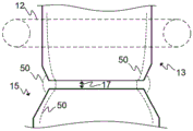
图5A和5B示意性地示出了根据本发明实施例的电动线性马达1的一部分。根据特定实施例,至少主要地用虚线示出了磁通量50的路径。可以看出,通量优选地通过动子5(或转子5)和定子4的磁齿13、15流过气隙17。5A and 5B schematically show a part of an electric
图5A示出了处于第一位置51的动子5,图5B示出了处于第二位置52的动子5。如图5A和5B所示,通量的路径至少主要根据动子5相对于定子4的位置而变化。FIG. 5A shows the
图6示意性地示出了动子5的磁芯3之一的不同部分的剖视图。第一部分61最靠近永磁体6。在该部分中,磁通量50的方向和大小由于由永磁体6引起的强场而保持基本恒定。在该区域中,磁芯3可以由实心铁磁材料制成,因为基本上没有由于永磁体附近的静磁场而产生涡流的风险。在第三部分63上,轭的通量从零变化到最大,因此,优选地,可以利用细丝材料或具有方形横截面的细丝元件或部分,并且它们布置成与磁通量的方向对齐。在第二部分62上,即在齿13中,通量从最小通过零变化到最大。通量的方向也随着其弯曲而变化,在这种情况下,约为90度。齿13、15可优选使用形状的层压型。FIG. 6 schematically shows a cross-sectional view of different parts of one of the
尽管未示出,但定子4的磁芯2可以与转子5的磁芯3类似地制造,然而,由于没有永磁体6,所以定子4的磁芯2仅包括第二部分62和第三部分63,即基本上用于定子4的齿15和轭。Although not shown, the magnetic core 2 of the
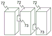
图7A和7B示意性地示出了根据本发明的两个实施例的磁芯2、3的部分。图7A示出了诸如电工钢层压板的层压型元件71。磁通量50基本上被限制在层压板内,因此,相对于芯由实心或“散装”材料制成的情况,涡流量减少了。图7B示出了磁芯2、3的细丝或细丝型元件或“条”,具有方形横截面的元件或部分72。具有方形横截面的细丝元件或部分72由于涡流的更短可能路径相对于具有相同横截面积的层压型元件71进一步减小了涡流损耗。尽管未在图中示出,但是磁芯的细丝或部分也可以具有圆形横截面。细丝可能不一定是直的,但也可能会经历弯曲的形状。Figures 7A and 7B schematically show parts of
为了确保磁芯2、3的刚性内部结构,例如,可以将具有方形横截面的层压型71或细丝元件或部分72或磁芯2、3的部分72彼此固定,例如通过接头元件73。这在图7C中示出,其中例如磁芯2、3的布置在芯的轭部分中的部分即第三部分63布置在具有基本上方形横截面的细丝元件72之间。这样,具有方形横截面的细丝元件72可以彼此分离,因此例如,进一步减小了涡流量。In order to ensure a rigid inner structure of the
图8A示出了根据本发明实施例的例如通过使用层压板制造的电动线性马达1的磁芯特别是其磁齿13、15的剖视图。尽管图8A中的气隙17示出为位于动子5的磁齿13与定子4的磁齿15之间,但比如图8A所示的气隙17也可以位于任何磁路中,例如在电感器芯中。可以看出,磁通量50遵循层压板的形状,因此在气隙17中弯曲。Fig. 8A shows a cross-sectional view of the magnetic core, in particular the
磁齿13、15的端部的形状由于使用层压板而具有矩形形状。The shape of the ends of the
图8B示出了根据本发明另一实施例的例如电动线性马达1的磁芯,特别是其磁齿13、15。磁齿的端部已经成形为使磁通量相对于气隙17聚焦。齿13、15可以由实心材料制成,例如通过铸造,或优选地,通过增材制造方法或3D打印,比如选择性激光烧结(SLS),或更优选地,选择性激光熔化(SLM)。例如,通过使用SLM,芯的每个部分可以成形为遵循最适用于磁芯的相应部分的3D形状。如图8B所示,相对于实心材料的结构,磁通量50倾向于在层压结构中弯曲较小,因此,通量50可以被图8B所示的齿13、15的结构聚焦。使图8B中的齿13、15朝向气隙17变窄,以便将通量50聚焦到气隙17中,从而导致气隙17中的通量密度更高。Fig. 8B shows a magnetic core, in particular its
根据本发明的实施例,磁齿13、15(一个或多个)可被制造为具有层压结构,比如通过利用增材制造方法或电工钢层压板。齿13、15相对于气隙17处的齿13、15的端部的变窄可以通过减少包括在齿13、15中的层压板量并且由此通过相对于远离齿13、15的所述端部的齿的部分使齿13、15在气隙17处的齿13、15的端部变窄来实现。可替代地或另外,可以将层压板合并,使得当使用芯时,将在两个或多个层压板中流动的磁通量50引导或聚焦到一个层压板或相对于远离气隙17的层压板的数量至少更少数量的层压板中,以使齿13、15更窄,以聚焦通量50。根据利用增材制造方法的实施例,齿13、15可被制造成在气隙17处朝着齿13、15的端部连续变窄。这也可以通过制造齿13、15来实现以具有层压结构。然后可以将层压板合并,使得齿13、15是连续的,这意味着在齿13、15的纵向长度方向上在层压板之间不存在不连续点。这允许磁通量50通过使齿13、15朝向气隙17变窄而被有效地聚焦。According to an embodiment of the invention, the
根据本发明的实施例,磁芯1可以用于电动线性马达1中。在这些马达中,切向力提供了电动线性马达1的推力,以使动子5沿着定子梁8运动,并且其与磁通密度的法向和切向分量的乘积成比例。气隙17中的最大磁通密度与芯材的饱和通量密度相同。然而,如果假设在图8A的磁芯中,气隙通量密度接近饱和通量密度,则在图8B所示的芯中,仅通过磁路的总磁阻的少量增加就可以实现饱和。在图8A所示的芯中,与图8B所示的芯相比,磁路的总磁阻将增加得多。因此,利用图8B所示的通量聚焦结构,可以使气隙的面积相对于图8A所示的磁芯减小约10-20%。According to an embodiment of the present invention, the
图9示出了根据本发明实施例的用于制造磁芯的方法的流程图。FIG. 9 shows a flowchart of a method for manufacturing a magnetic core according to an embodiment of the present invention.
在90,参考启动阶段,可能发生必要的任务,比如获得部件和系统,以及校准和其他配置。必须特别注意各个已经和材料选择的协同作用。可以在各种部件和(子)系统之间建立通信和电连接。在90,可以获得包括不同金属或金属合金的特定材料。At 90 , referring to the start-up phase, necessary tasks may occur, such as obtaining components and systems, as well as calibration and other configuration. Particular attention must be paid to the synergistic effects of individual materials and material selection. Communications and electrical connections can be established between the various components and (sub)systems. At 90, specific materials including different metals or metal alloys can be obtained.
在91,为磁芯的至少两个部分中的每个定义磁通量的至少一个特征。这可能需要利用磁芯的相应部分中的磁通量的大小作为磁通量的至少一个特征。例如,在磁芯的被设计为高的部分中的磁通量的大小且因此具有高磁饱和度的某些铁磁材料是更好适合的。可替代地或另外,可以将磁通量的变化用作特征。在磁芯的某些部分中,通量可被设计为基本恒定,而在其他部分中可以显著变化。这可能与磁通量的大小的变化和/或磁通量的方向有关。At 91, at least one characteristic of magnetic flux is defined for each of at least two portions of the magnetic core. This may entail utilizing the magnitude of the magnetic flux in the corresponding portion of the core as at least one characteristic of the magnetic flux. For example, certain ferromagnetic materials that are designed to have a high magnetic flux magnitude and thus high magnetic saturation in parts of the core are better suited. Alternatively or additionally, a change in magnetic flux may be used as a feature. The flux can be designed to be substantially constant in some parts of the core, while it can vary significantly in other parts. This may be related to a change in the magnitude of the magnetic flux and/or the direction of the magnetic flux.
关于磁通量的至少一个特征的定义,图6示出了该问题。在第一部分61中,磁通量保持基本恒定。在第二部分62中,通量从最小通过零变化到最大。在第三部分63中,通量从零变化到最大。Regarding the definition of at least one characteristic of magnetic flux, Figure 6 illustrates the problem. In the
在92,发生基于所定义的代表磁芯的相应部分的至少一个特征来确定磁芯的至少两个部分中的每个的类型。例如,实心材料可以用于其中通量被设计为保持基本恒定的部分。在其中通量快速变化的部分中,可以使用层压型或具有方形横截面积的类型即方形元件72或部分72,以减小涡流。如果大小的变化相对较小,则可以使用层压型而不是方形部分72。结合图6示出和描述不同的部分。At 92 , determining a type of each of the at least two portions of the magnetic core based on at least one characteristic defined representative of the respective portion of the magnetic core occurs. For example, solid material may be used in sections where the flux is designed to remain substantially constant. In sections where the flux changes rapidly, a laminated type or a type with a square cross-sectional area, ie, a
在93,发生获得或生产具有确定类型的磁芯的至少两个部分。这些部分可以作为现成的获得,例如作为分离的或集成的层压板或方形部分或实心材料部分。这些部分或这些部分的一部分可以通过增材制造方法比如SLM铸造或制造。At 93, obtaining or producing at least two parts of a magnetic core of the determined type takes place. These parts can be obtained as ready-made, for example as separate or integrated laminates or square parts or solid material parts. These parts or parts of these parts may be cast or manufactured by additive manufacturing methods such as SLM.
可以通过使用钴铁和硅铁材料来制造磁芯部分。然而,也可以仅使用铁。根据一实施例,例如,可以使用铁-钒(Fe-V)或铁-钴-钒(Fe-Co-V)材料作为芯材料将钒结合到磁芯材料中。钒的添加降低了材料的饱和磁通密度并增加了材料的电阻率,因此降低了涡流。The magnetic core part can be manufactured by using cobalt-iron and ferrosilicon materials. However, it is also possible to use only iron. According to an embodiment, for example, iron-vanadium (Fe-V) or iron-cobalt-vanadium (Fe-Co-V) material may be used to incorporate vanadium into the magnetic core material. The addition of vanadium reduces the saturation flux density of the material and increases the resistivity of the material, thus reducing eddy currents.
在94,发生将磁芯的至少两个部分集成在一起的可选步骤。获得或生产的至少两个部分可以彼此焊接。根据本发明的实施例,磁芯的至少两个部分可以通过增材制造方法例如SLM或SLS基本同时地制造。这样就形成了单件芯部分或甚至准备好磁芯。At 94, an optional step of integrating at least two portions of the magnetic core together occurs. At least two parts obtained or produced can be welded to each other. According to an embodiment of the invention, at least two parts of the magnetic core may be manufactured substantially simultaneously by additive manufacturing methods such as SLM or SLS. This creates a one-piece core section or even a ready-made core.
这意味着可以制造磁芯,使得芯根据混合物而在不同位置处具有不同类型的部分,例如,在用于磁芯的合金的情况下,可以适应地变化。这意味着磁芯不是由单一材料制成,而是磁芯的不同部分(例如,磁通量以某种方式流动的部分)由不同的材料制成或至少具有构成该材料的两种或更多种元素的不同混合比。因此,磁芯可以被制成各向异性的。This means that the core can be manufactured such that the core has different types of parts at different positions depending on the mixture, eg in the case of the alloy used for the core, can be adapted. This means that the core is not made of a single material, but that different parts of the core (for example, the part where the magnetic flux flows in a certain way) are made of different materials or at least have two or more of the materials that make up Different mixing ratios of elements. Therefore, the magnetic core can be made anisotropic.
在99,方法执行结束或停止。该方法可以进一步包括去除多余的部分,比如支撑部分,其在铸造或利用增材制造方法之后可能必须去除。At 99, method execution ends or stops. The method may further include removing redundant parts, such as support parts, which may have to be removed after casting or utilizing additive manufacturing methods.
根据本发明的实施例,可以首先获得或生产磁芯的一部分,然后可以通过诸如SLM或SLS的增材制造方法生产附着到第一部分的一个或多个其他部分。因此,并非必须同时获得或生产所有部分,然后将它们彼此集成,而是某些部分可能“生长”在其他部分上。在本文中,生长是指例如在先前阶段中制造的芯部分上使用增材制造方法来制造新的芯部分,比如通过轧制或铸造或者甚至通过利用相似或不同的增材制造方法。According to an embodiment of the invention, a part of the magnetic core may first be obtained or produced, and then one or more other parts attached to the first part may be produced by additive manufacturing methods such as SLM or SLS. So instead of having to acquire or produce all parts at the same time and then integrate them with each other, some parts may "grow" on other parts. In this context, growing means for example using an additive manufacturing method on a core part manufactured in a previous stage to manufacture a new core part, such as by rolling or casting or even by utilizing a similar or different additive manufacturing method.
根据本发明的实施例,磁芯包括在两个磁齿13、15之间的气隙17。因此,制造方法可以包括生产磁齿13、15,使得齿13、15的位于气隙17处的端部的横截面积相对于齿13、15的在其他位置处的横截面积更小,以将磁通量聚集在气隙17处。According to an embodiment of the invention, the magnetic core comprises an
根据一实施例,磁芯可被制造为使得例如在用于磁芯的合金的情况下,混合物可以在磁芯的不同部分中适应性地变化。这意味着磁芯不是由单一材料制成,而是磁芯的不同部分(例如磁通量以某种方式流动的部分)由不同的材料制成或至少具有构成该材料的两种或更多种元素的不同混合比。因此,磁芯可以被制成各向异性的。According to an embodiment, the magnetic core can be manufactured such that, eg in the case of alloys used for the magnetic core, the mixture can be adaptively varied in different parts of the magnetic core. This means that the core is not made of a single material, but that different parts of the core (such as the part where the magnetic flux flows in a certain way) are made of different materials or at least have two or more elements that make up that material different mixing ratios. Therefore, the magnetic core can be made anisotropic.
根据一实施例,磁芯可以通过烧结由铁或铁钴材料制成。烧结可以优选地是激光烧结,比如通过选择性激光烧结。According to an embodiment, the magnetic core may be made of iron or iron-cobalt material by sintering. Sintering may preferably be laser sintering, such as by selective laser sintering.
根据一实施例,由铁制成的磁芯的表面坚硬且刚性并且在破裂之前在拉伸应力下具有良好的延展性,可以用作马达的制动表面。According to an embodiment, the surface of the magnetic core made of iron, which is hard and rigid and has good ductility under tensile stress before cracking, can be used as the braking surface of the motor.
通过利用根据本发明的一些实施例的增材制造技术,在电动线性马达1的情况下能够制造窄的定子梁8,这是由于以下事实:通过优化磁芯2可以使磁芯2更小或更窄,如关于本发明的各种实施例在本文中描述。By utilizing additive manufacturing techniques according to some embodiments of the invention,
根据一实施例,磁芯可被制造为包括例如层压状、平面、实心均质材料或圆柱体的部分,和/或此外,可以表现出3D形状,比如用于以最佳方式引导磁通量的曲线。According to an embodiment, the magnetic core can be manufactured to comprise, for example, laminated, planar, solid homogeneous material or cylindrical parts, and/or in addition, can exhibit 3D shapes, such as for guiding the magnetic flux in an optimal way curve.
在以上给出的描述中提供的特定示例不应被解释为限制所附权利要求的适用性和/或解释。除非另有明确说明,否则以上给出的描述中提供的示例的列表和组不是穷举的。The specific examples provided in the description given above should not be construed as limiting the applicability and/or interpretation of the appended claims. The lists and groups of examples provided in the description given above are not exhaustive unless expressly stated otherwise.
Claims (12)
Applications Claiming Priority (3)
| Application Number | Priority Date | Filing Date | Title |
|---|---|---|---|
| EP17190378.4A EP3454455B1 (en) | 2017-09-11 | 2017-09-11 | Method for manufacturing a magnetic core for an electric machine, an electric machine utilizing the magnetic core thereof, and a magnetic core |
| EP17190378.4 | 2017-09-11 | ||
| PCT/EP2018/074261 WO2019048659A1 (en) | 2017-09-11 | 2018-09-10 | Method for manufacturing a magnetic core of an electric machine, an electric machine utilizing the magnetic core thereof, and a magnetic core |
Publications (2)
| Publication Number | Publication Date |
|---|---|
| CN111095732A CN111095732A (en) | 2020-05-01 |
| CN111095732B true CN111095732B (en) | 2023-05-23 |
Family
ID=59858559
Family Applications (1)
| Application Number | Title | Priority Date | Filing Date |
|---|---|---|---|
| CN201880058892.7A Active CN111095732B (en) | 2017-09-11 | 2018-09-10 | Method for manufacturing magnetic core of motor, motor using same, and magnetic core |
Country Status (4)
| Country | Link |
|---|---|
| US (1) | US11398345B2 (en) |
| EP (1) | EP3454455B1 (en) |
| CN (1) | CN111095732B (en) |
| WO (1) | WO2019048659A1 (en) |
Families Citing this family (4)
| Publication number | Priority date | Publication date | Assignee | Title |
|---|---|---|---|---|
| GB2570927B (en) * | 2018-02-12 | 2023-05-31 | Epropelled Ltd | Electromagnetic devices |
| CN112260422A (en) * | 2020-10-14 | 2021-01-22 | 中车株洲电机有限公司 | Motor and axial magnetic suspension bearing stator thereof |
| JP2022127931A (en) * | 2021-02-22 | 2022-09-01 | 山洋電気株式会社 | Motor armature structure and manufacturing method thereof |
| DE102022115198A1 (en) * | 2022-06-17 | 2023-12-28 | Ford Global Technologies, Llc | Method for producing a rotor element for a rotor of an electrical machine, rotor element, rotor, electrical machine and motor vehicle |
Citations (13)
| Publication number | Priority date | Publication date | Assignee | Title |
|---|---|---|---|---|
| CN1279819A (en) * | 1997-09-22 | 2001-01-10 | 泽夫·利普克斯 | Core and coil structure and method of making same |
| JP2005065479A (en) * | 2003-07-29 | 2005-03-10 | Fanuc Ltd | Motor and motor manufacturing apparatus |
| CN101266867A (en) * | 2007-01-23 | 2008-09-17 | 通用汽车环球科技运作公司 | Methods for manufacturing motor core parts with magnetic orientation |
| WO2010109272A2 (en) * | 2009-03-26 | 2010-09-30 | Vacuumschmelze Gmbh & Co. Kg | Laminated core having a soft magnetic material and method for joining core sheets in a bonded manner to form a soft-magnetic laminated core |
| CN103178624A (en) * | 2011-12-22 | 2013-06-26 | 三星电机株式会社 | Laminated iron core and method for manufacturing the same |
| CN103904836A (en) * | 2014-03-07 | 2014-07-02 | 江苏通达动力科技股份有限公司 | Laminating device and method of direct-drive permanent magnet generator stator core |
| CN104137390A (en) * | 2012-02-14 | 2014-11-05 | 日本发条株式会社 | Stator core for motor and manufacturing method therefor |
| CN105324204A (en) * | 2013-07-03 | 2016-02-10 | Posco公司 | Method for manufacturing electrical steel sheet laminated core having reduced core loss and increased strength, and laminated core produced by the same |
| CN105453709A (en) * | 2013-03-14 | 2016-03-30 | 德克萨斯州大学系统董事会 | Methods and systems for embedding filaments into 3D structures, structural components and structural electronic, electromagnetic and electromechanical components/devices |
| CN105703565A (en) * | 2014-12-09 | 2016-06-22 | 株式会社三井高科技 | Laminate and method for manufacturing the same and method for manufacturing laminated core |
| CN105743299A (en) * | 2014-12-24 | 2016-07-06 | 株式会社三井高科技 | Laminate body, method for manufacturing laminate body, and method for manufacturing rotor |
| CN106688057A (en) * | 2014-09-09 | 2017-05-17 | 普莱默公司 | Flexible soft magnetic core, antenna with flexible soft magnetic core and method for producing a flexible soft magnetic core |
| CN106796835A (en) * | 2014-08-12 | 2017-05-31 | Abb瑞士股份有限公司 | The magnet in the region with different magnetic properties and the method for forming this magnet |
Family Cites Families (12)
| Publication number | Priority date | Publication date | Assignee | Title |
|---|---|---|---|---|
| GB2149226B (en) * | 1983-09-05 | 1987-09-09 | Papst Motoren Gmbh & Co Kg | Collectorless d c motor |
| JP4003382B2 (en) * | 2000-07-14 | 2007-11-07 | セイコーエプソン株式会社 | Generator and electronically controlled mechanical clock |
| US7845065B2 (en) * | 2007-11-07 | 2010-12-07 | Gm Global Technology Operations, Inc. | Method of making a rotating electric machine stator core |
| JP5020034B2 (en) * | 2007-11-22 | 2012-09-05 | 三菱電機株式会社 | Rotating electric machine |
| EP2961040B1 (en) * | 2013-02-20 | 2019-05-08 | Mitsubishi Electric Corporation | Electric motor having embedded permanent magnets |
| US9621013B2 (en) * | 2013-03-15 | 2017-04-11 | Ingersoll-Rand Company | Rotating machine with magnetic bearing |
| WO2015198961A1 (en) * | 2014-06-24 | 2015-12-30 | 株式会社クボタ | Stator of electric motor and cooling structure for dynamo-electric machine |
| US9906111B2 (en) * | 2014-10-21 | 2018-02-27 | Xiuhong Sun | Fine element magnet array |
| US10483812B2 (en) * | 2014-12-31 | 2019-11-19 | Ingersoll-Rand Company | Electrical machine and method of manufacture |
| US20170063183A1 (en) * | 2015-08-29 | 2017-03-02 | Abb Technology Ag | Electrical machines and fabrication methods therefor |
| US20170126087A1 (en) * | 2015-10-30 | 2017-05-04 | Rod F. Soderberg | Device including material originating from magnetic particles providing structural and magnetic capabilities |
| TWI576872B (en) * | 2015-12-17 | 2017-04-01 | 財團法人工業技術研究院 | Fabrication method of magnetic device |
-
2017
- 2017-09-11 EP EP17190378.4A patent/EP3454455B1/en active Active
-
2018
- 2018-09-10 CN CN201880058892.7A patent/CN111095732B/en active Active
- 2018-09-10 WO PCT/EP2018/074261 patent/WO2019048659A1/en active Application Filing
-
2020
- 2020-02-10 US US16/786,221 patent/US11398345B2/en active Active
Patent Citations (13)
| Publication number | Priority date | Publication date | Assignee | Title |
|---|---|---|---|---|
| CN1279819A (en) * | 1997-09-22 | 2001-01-10 | 泽夫·利普克斯 | Core and coil structure and method of making same |
| JP2005065479A (en) * | 2003-07-29 | 2005-03-10 | Fanuc Ltd | Motor and motor manufacturing apparatus |
| CN101266867A (en) * | 2007-01-23 | 2008-09-17 | 通用汽车环球科技运作公司 | Methods for manufacturing motor core parts with magnetic orientation |
| WO2010109272A2 (en) * | 2009-03-26 | 2010-09-30 | Vacuumschmelze Gmbh & Co. Kg | Laminated core having a soft magnetic material and method for joining core sheets in a bonded manner to form a soft-magnetic laminated core |
| CN103178624A (en) * | 2011-12-22 | 2013-06-26 | 三星电机株式会社 | Laminated iron core and method for manufacturing the same |
| CN104137390A (en) * | 2012-02-14 | 2014-11-05 | 日本发条株式会社 | Stator core for motor and manufacturing method therefor |
| CN105453709A (en) * | 2013-03-14 | 2016-03-30 | 德克萨斯州大学系统董事会 | Methods and systems for embedding filaments into 3D structures, structural components and structural electronic, electromagnetic and electromechanical components/devices |
| CN105324204A (en) * | 2013-07-03 | 2016-02-10 | Posco公司 | Method for manufacturing electrical steel sheet laminated core having reduced core loss and increased strength, and laminated core produced by the same |
| CN103904836A (en) * | 2014-03-07 | 2014-07-02 | 江苏通达动力科技股份有限公司 | Laminating device and method of direct-drive permanent magnet generator stator core |
| CN106796835A (en) * | 2014-08-12 | 2017-05-31 | Abb瑞士股份有限公司 | The magnet in the region with different magnetic properties and the method for forming this magnet |
| CN106688057A (en) * | 2014-09-09 | 2017-05-17 | 普莱默公司 | Flexible soft magnetic core, antenna with flexible soft magnetic core and method for producing a flexible soft magnetic core |
| CN105703565A (en) * | 2014-12-09 | 2016-06-22 | 株式会社三井高科技 | Laminate and method for manufacturing the same and method for manufacturing laminated core |
| CN105743299A (en) * | 2014-12-24 | 2016-07-06 | 株式会社三井高科技 | Laminate body, method for manufacturing laminate body, and method for manufacturing rotor |
Also Published As
| Publication number | Publication date |
|---|---|
| US11398345B2 (en) | 2022-07-26 |
| WO2019048659A1 (en) | 2019-03-14 |
| EP3454455B1 (en) | 2025-06-25 |
| CN111095732A (en) | 2020-05-01 |
| EP3454455A1 (en) | 2019-03-13 |
| US20200176183A1 (en) | 2020-06-04 |
Similar Documents
| Publication | Publication Date | Title |
|---|---|---|
| CN111095732B (en) | Method for manufacturing magnetic core of motor, motor using same, and magnetic core | |
| US11532963B2 (en) | Torque tunnel Halbach Array electric machine | |
| JP6848050B2 (en) | Electromechanical equipment | |
| AU2008209912B2 (en) | Ring motor | |
| US8384252B2 (en) | Linear motor | |
| US7839029B2 (en) | Linear motor | |
| AU2011313817B2 (en) | Electromagnetic machine | |
| CN101023570B (en) | Secondary part of an electric machine | |
| US20220045559A1 (en) | Segmented stator for a permanent magnet electric machine having a fractional-slot concentrated winding | |
| US10491061B2 (en) | Rotor for a reluctance machine | |
| US8653713B2 (en) | Magnetic circuit structure | |
| EP3540917B1 (en) | Rotary electric machine | |
| EP2779373B1 (en) | Rotating machine with magnetic bearing | |
| US20250007336A1 (en) | Rotary electric machine | |
| Burnand et al. | Optimization of shape and topology for slotless windings in BLDC machines | |
| US20220352775A1 (en) | Coil structures | |
| Shen et al. | Analysis and optimization of a modular stator core with segmental teeth and solid back iron for pm electric machines | |
| WO2017008085A1 (en) | An improved electric linear motor/generator | |
| JP4323940B2 (en) | Exciter, field machine, and synchronous machine using the same | |
| JP2005253259A (en) | Linear electromagnetic actuator | |
| HK40019018A (en) | Method for manufacturing a magnetic core of an electric machine, an electric machine utilizing the magnetic core thereof, and a magnetic core | |
| HK40019018B (en) | Method for manufacturing a magnetic core of an electric machine, an electric machine utilizing the magnetic core thereof, and a magnetic core | |
| JP2018050430A (en) | Linear motor | |
| US20220069681A1 (en) | Method for winding a heavy gauge toroidal coil of an electric machine | |
| JP6682881B2 (en) | Rotating electric machine |
Legal Events
| Date | Code | Title | Description |
|---|---|---|---|
| PB01 | Publication | ||
| PB01 | Publication | ||
| SE01 | Entry into force of request for substantive examination | ||
| SE01 | Entry into force of request for substantive examination | ||
| REG | Reference to a national code |
Ref country code: HK Ref legal event code: DE Ref document number: 40019018 Country of ref document: HK |
|
| GR01 | Patent grant | ||
| GR01 | Patent grant |