CN1110759A - Gas turbine combined cycle system - Google Patents
Gas turbine combined cycle system Download PDFInfo
- Publication number
- CN1110759A CN1110759A CN94119608A CN94119608A CN1110759A CN 1110759 A CN1110759 A CN 1110759A CN 94119608 A CN94119608 A CN 94119608A CN 94119608 A CN94119608 A CN 94119608A CN 1110759 A CN1110759 A CN 1110759A
- Authority
- CN
- China
- Prior art keywords
- combustion gas
- steam generator
- diffuser pipe
- gas turbine
- pipe
- Prior art date
- Legal status (The legal status is an assumption and is not a legal conclusion. Google has not performed a legal analysis and makes no representation as to the accuracy of the status listed.)
- Pending
Links
Images
Classifications
-
- F—MECHANICAL ENGINEERING; LIGHTING; HEATING; WEAPONS; BLASTING
- F02—COMBUSTION ENGINES; HOT-GAS OR COMBUSTION-PRODUCT ENGINE PLANTS
- F02C—GAS-TURBINE PLANTS; AIR INTAKES FOR JET-PROPULSION PLANTS; CONTROLLING FUEL SUPPLY IN AIR-BREATHING JET-PROPULSION PLANTS
- F02C1/00—Gas-turbine plants characterised by the use of hot gases or unheated pressurised gases, as the working fluid
-
- F—MECHANICAL ENGINEERING; LIGHTING; HEATING; WEAPONS; BLASTING
- F01—MACHINES OR ENGINES IN GENERAL; ENGINE PLANTS IN GENERAL; STEAM ENGINES
- F01D—NON-POSITIVE DISPLACEMENT MACHINES OR ENGINES, e.g. STEAM TURBINES
- F01D25/00—Component parts, details, or accessories, not provided for in, or of interest apart from, other groups
- F01D25/30—Exhaust heads, chambers, or the like
-
- F—MECHANICAL ENGINEERING; LIGHTING; HEATING; WEAPONS; BLASTING
- F02—COMBUSTION ENGINES; HOT-GAS OR COMBUSTION-PRODUCT ENGINE PLANTS
- F02C—GAS-TURBINE PLANTS; AIR INTAKES FOR JET-PROPULSION PLANTS; CONTROLLING FUEL SUPPLY IN AIR-BREATHING JET-PROPULSION PLANTS
- F02C6/00—Plural gas-turbine plants; Combinations of gas-turbine plants with other apparatus; Adaptations of gas- turbine plants for special use
- F02C6/18—Plural gas-turbine plants; Combinations of gas-turbine plants with other apparatus; Adaptations of gas- turbine plants for special use using the waste heat of gas-turbine plants outside the plants themselves, e.g. gas-turbine power heat plants
-
- F—MECHANICAL ENGINEERING; LIGHTING; HEATING; WEAPONS; BLASTING
- F22—STEAM GENERATION
- F22B—METHODS OF STEAM GENERATION; STEAM BOILERS
- F22B1/00—Methods of steam generation characterised by form of heating method
- F22B1/02—Methods of steam generation characterised by form of heating method by exploitation of the heat content of hot heat carriers
- F22B1/18—Methods of steam generation characterised by form of heating method by exploitation of the heat content of hot heat carriers the heat carrier being a hot gas, e.g. waste gas such as exhaust gas of internal-combustion engines
- F22B1/1807—Methods of steam generation characterised by form of heating method by exploitation of the heat content of hot heat carriers the heat carrier being a hot gas, e.g. waste gas such as exhaust gas of internal-combustion engines using the exhaust gases of combustion engines
- F22B1/1815—Methods of steam generation characterised by form of heating method by exploitation of the heat content of hot heat carriers the heat carrier being a hot gas, e.g. waste gas such as exhaust gas of internal-combustion engines using the exhaust gases of combustion engines using the exhaust gases of gas-turbines
-
- F—MECHANICAL ENGINEERING; LIGHTING; HEATING; WEAPONS; BLASTING
- F05—INDEXING SCHEMES RELATING TO ENGINES OR PUMPS IN VARIOUS SUBCLASSES OF CLASSES F01-F04
- F05D—INDEXING SCHEME FOR ASPECTS RELATING TO NON-POSITIVE-DISPLACEMENT MACHINES OR ENGINES, GAS-TURBINES OR JET-PROPULSION PLANTS
- F05D2220/00—Application
- F05D2220/60—Application making use of surplus or waste energy
Landscapes
- Engineering & Computer Science (AREA)
- Chemical & Material Sciences (AREA)
- Combustion & Propulsion (AREA)
- Mechanical Engineering (AREA)
- General Engineering & Computer Science (AREA)
- Life Sciences & Earth Sciences (AREA)
- Sustainable Development (AREA)
- Sustainable Energy (AREA)
- Physics & Mathematics (AREA)
- Thermal Sciences (AREA)
- Engine Equipment That Uses Special Cycles (AREA)
Abstract
An improved gas turbine combined cycle system having a diffuser duct between the gas turbine and steam generator. The diffuser duct has boundary layer suction to prevent gas jet separation, thereby reducing pressure loss and improving gas velocity profiles in the duct, while eliminating the need for internal flow controls. The gas turbine combined cycle system can be vertically oriented to reduce the plan area of the system and provide for convenient use of a symmetrical diffuser duct and the use of forced circulation on the water side of the steam generator.
Description
The present invention relates generally to the combustion gas combined cycle system, relates in particular to the system with a combustion gas turbine and a heat recovery steam generator.
In generating work, be known for raising the efficiency the various systems that combustion gas turbine, steam generator and steam turbine are combined.A kind of such system has adopted a combustion gas turbine to connect same steam generator, and wherein, combustion gas turbine utilizes waste-heat power generation, and it not only produces electric power, and produces hot combustion gas, and hot combustion gas is used for heat recovery steam generator then.
When hot combustion gas when the combustion gas turbine enters heat recovery steam generator (HRSG) because combustion gas turbine outlet is different with the size of HRSG, the speed of this combustion gas must reduce by 10 times.This speed reduces to be finished in diffuser pipe.Traditional diffuser pipe is asymmetric, and it has a horizontally extending planomural and an acclivitous expansion wall.In this typical diffuser pipe, the angle of flare of upper wall is much larger than 15 °, and combustion gas expansion perhaps can be joined in these 15 ° of angles, and the combustion gas in the diffuser pipe is separated and backflow.The reason that employing has greater than the diffuser pipe of 15 ° of expansion ratios is for economic consideration, is in order to make cost and requisite space minimum.Yet, unfortunately, exist since adopted that diffuser pipe with big expansion ratio causes follow the relevant problem of gas jet separation.At first, this expansion has caused total system pressure loss supercharging.Secondly, gas jet separation causes velocity flow profile poorer than desirable, and this ideal distribution is to have considered diffusion burner and the pollution control device that is adopted in this pipe.
Traditional solution for the problem of velocity flow profile difference is to adopt flow dontroller in diffuser pipe always.The shortcoming of sort controller is expensive, and the pressure loss total in this system is increased.
Above-mentioned this traditional gas turbine combined cycle system comprises the combustion gas turbine of a horizontal orientation, and it sends into waste gas the heat recovery steam generator of the adjacent combustion gas turbine of level.Often rely on natural circulation at the HRSG that the U.S. used and made in the water side.The forced circulation system also is known, more generally uses in Europe.
Purpose of the present invention provides a kind of combustion gas turbine combined system with diffuser pipe, wherein, has eliminated the fuel gas return-flow in the diffuser pipe basically.
Another object of the present invention provides the gas turbine combined cycle system with velocity flow profile of having improved.
Further object of the present invention provides a kind of like this diffuser pipe that is used for the combustion gas turbine combined system, wherein need not the inner stream flow controller.
Another purpose of the present invention provides a kind of like this combustion gas turbine one steam generator combined system, and it only needs the small device space region.
Of the present invention also have a purpose to provide a kind of like this gas turbine combined cycle system, and it provides convenience for the use of the symmetrical Diffuser of arranged perpendicular between combustion gas turbine and steam generator.
Another object of the present invention provides a kind of gas turbine combined cycle system with the pressure loss that has reduced.
A further object of the present invention provides a kind of like this turbine one steam generator combined system, and it allows the exhaust steam pipe that adopts than weak point on steam generator.
Of the present invention also have a purpose to provide a kind of gas turbine combined cycle system that has reduced heating surface that has.
With reference to the following specification of doing with respect to accompanying drawing, other purpose of the present invention and characteristics military order become obvious.
A preferred embodiment of the present invention is a gas turbine combined cycle system.This system comprises a combustion gas turbine of discharging combustion gas, a steam generator that receives combustion gas, one is between combustion gas turbine and the steam generator, be used to reduce the diffuser pipe of the flow velocity of combustion gas before entering steam generator, and be used for extracting combustion gas out so that the overall presure drop in the diffuser pipe reduces to minimum boundary layer negative pressure device along the internal surface of diffuser pipe expansion wall.System of the present invention helps the complete expansion of combustion gas in diffuser pipe, and improves the velocity flow profile that combustion gas enters steam generator.
In a specific preferred embodiment of the present invention, the boundary layer negative pressure device is that pipe is extracted in a combustion gas out, and its entrance point forms in diffuser pipe expansion wall, and its outlet end is connected in the turbine import.In another specific preferred embodiment, the entrance point that pipe is extracted in combustion gas out is in the wall of diffuser pipe, and exhaust end connects steam generator.In this embodiment, comprise the feedway that is used for combustion gas is delivered to from entrance point outlet end.In the 3rd specific preferred embodiment of the present invention, this boundary layer negative pressure device comprises some pipes or conduit, and each pipe has an entrance point that forms in the diffusion tube wall, and on this entrance point position, the pressure in the diffuser pipe is P1; Also have an outlet end that forms in diffuser pipe, on this outlet end position, the pressure in the diffuser pipe is less than P1; Combustion gas utilizes the venturi effect to circulate through the boundary layer negative pressure device.The outlet/inlet waste gas speed ratio that diffuser pipe of the present invention preferably provides is at least 5-15, is preferably 9-11.Described diffuser pipe preferably has at least one with about 15-90 °, best about 30-60 ° the wall of the angle of flare.In diffuser pipe of the present invention, waste gas is not experience backflow basically.
Another preferred embodiment of the present invention is that gas turbine combined cycle system comprises the combustion gas turbine of the discharge combustion gas of a vertical orientation; The steam generator of the reception combustion gas of a vertical orientation, the residing vertical height of this steam generator are pump circulation than the height of turbine in water side or turbine side; One between the diffuser pipe that is used to reduce the flow velocity of combustion gas before entering steam generator between turbine and the steam generator.In this embodiment, diffuser pipe is preferably roughly symmetrical structure shape, and steam generator directly enters flue with waste gas.
Another preferred embodiment of the present invention is a kind of method that reduces the interior gas jet separation of diffuser pipe of gas turbine combined cycle system.This method comprise utilize the boundary layer negative pressure device along the inner wall surface of diffuser pipe enlarged portion extract combustion gas out and in the upstream or downstream position introduce the combustion gas that is drawn out of again.
Of the present invention also have an embodiment to form the method for gas turbine combined cycle system, and this system has a combustion gas turbine, a steam generator and an intervenient diffuser pipe.This method comprises makes combustion gas turbine, and diffuser pipe and steam generator vertical orientation make the vertical height of steam generator be higher than the step of combustion gas turbine.This method comprises also and is provided for making water/vapour mixture in the turbine side that promptly the water side is utilized the step of pump circulation through the circulation means of steam generator.
Therefore, the present invention includes some steps and these steps one or more relations in describing in detail below with respect to other each step, and the product with characteristics, character and relation of the member of being enumerated.
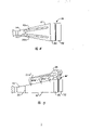
The gas turbine combined cycle system of Fig. 1 Succinct representation routine;
Fig. 2 Succinct representation does not adopt the waste gas flow pattern in the diffuser pipe of gas turbine combined cycle system of routine of flow dontroller;
The front view of the diffuser pipe of Fig. 3 Succinct representation gas turbine combined cycle system of the present invention;
The top view of Fig. 4 presentation graphs 3 diffuser pipes;
Second embodiment of Fig. 5 Succinct representation diffuser pipe of the present invention;
Fig. 6 Succinct representation vertical orientation gas turbine combined cycle system of the present invention comprises the 3rd embodiment of diffuser pipe.
With reference to each accompanying drawing, especially Fig. 1 has wherein represented conventional turbine-HRSG system, and total is marked with 10.This system comprises a gas generator 12, one compressors 13 and a combustion gas turbine 14, and they are linked to be the polyphone state.Turbine 14 has an import 21 and outlet 22.Waste gas is flowed through a diffuser pipe 16 and the import that enters heat recovery steam generator 18 from combustion gas turbine 14.HRSG18 comprises a superheater 30 and arranges boiler 32 in one of this superheater downstream.Because turbine outlet 22 inlets less than HRSG are so need Diffuser 16.Diffuser 16 is asymmetric, has 23 and outlets 25 of 19, one inlets of 17, one acclivitous expansion upper walls of a horizontal bottom wall.This structure shape is convenient to suitable connection the between turbine 14 and HRSG18, turbine need not be raised.If diffuser pipe 16 is expanded with symmetric mode, it need be raised originally.
When the diffuser pipe angle of flare with respect to the horizontal plane during, and when in diffuser pipe, not adopting the inner stream flow controller, may have through the gas flow of diffuser pipe and to be similar to distribution shown in Figure 2 greater than about 15 °.As shown in the figure, flow into HRSG18 along the combustion gas of the bottom of diffuser pipe 16, and the flow separation that experiences a backpressure gradient and cause refluxing along the combustion gas of upper wall.The pressure that this flow pattern has increased whole system falls, thereby system effectiveness is descended.This flow pattern also makes the interior heat transfer surface of HRSG effectively not utilize, and this point also will describe in detail below.
As the replacement scheme that in diffuser pipe, adopts the inner stream flow controller greater than 15 ° of angle expansions, one of diffuser pipe 16 of the present invention ' adopt is such as at the boundary layer negative pressure system shown in Fig. 3-6, as as shown in these figure, the boundary layer combustion gas is drawn out of from the enlarged portion of diffuser pipe, then in the upstream or downstream position introduce again in this system.This extraction has prevented basically or has reduced turbulent flow and backflow at least that this turbulent flow and backflow can come across the enlarged portion in the diffuser pipe under reverse situation.
The boundary layer negative pressure can realize with several different methods.Shown in Fig. 3 and 4, a kind of technology is to use the Venturi effect, and wherein the combustion gas that promptly has big cross-sectional area in the low velocity zone of diffuser pipe is drawn out of, and has at a high speed thereby introduce again the another location of low pressure.As shown in Figure 3, combustion gas along diffuser pipe 16 ' length uniformly-spaced be drawn out of through narrow pipe 20a-20c on the position at three.Press in the present embodiment the work of Venturi effect all one the cover in three the pipe 20a-20c, each pipe has an outlet end that is connected in turbine low tension outlet 22.
In the asymmetric diffuser pipe shown in Fig. 3 and 4, only need to apply the boundary layer negative pressure along the enlarged portion of wall.Can adopt any amount of pipe 20.The particular system in the running is depended in number of tubes and position, comprises the size of combustion gas turbine and steam generator, the angle of flare of diffuser pipe, and through the flow of the combustion gas of this pipe.
As shown in Figure 5, available pipe 20a '-20c ' replaces, with combustion gas from diffuser pipe 16 ' transport to downstream position.In this embodiment,, can apply negative pressure,, and again HRSG18 ' be introduced in combustion gas at suitable position so that suction side bleeds from the enlarged portion of this pipe along the boundary layer by means of a fan 24 that suitably is installed on pipe 20a '-20b '.Hope is introduced this combustion gas again in locations of low pressure.All places all is suitable usually.The selection of position depends in part on heat load and performance requirement, and ordinary person skilled in this field can make suitable selection.
A specific preferred embodiment of the present invention is shown in Fig. 6.In this embodiment, described combustion gas turbine HRSG system be vertical orientation with, 10 ' mark.This system comprise a generator 12 in the lower end ', gas compressor 13 ' and the combustion gas turbine that is connected in gas compressor top downstream above generator, turbine has an import 21.One symmetrical diffuser pipe 16 ' " with the outlet of combustion gas from turbine 14 ' introducing HRSG18 '.Because the result of system's 10 vertical orientations, HRSG18 can be disposed easily by pump circulation and be turned round.
Guaranteed to transfer to the minimum mixed gas flow of all boiler tubes of steam generator in the pump circulation of the water-steam mixture of HRSG or any steam generator water side.Because the improvement of this control can be adopted thin slightly boiler tube, because the cooling of these pipes improves by means of the internal soundness flow.For low pressure steam, these difference can be dwindled, with and need not pump circulation.Yet, increase with vapor pressure, need pump circulation more.In the forced circulation system that letter is shown in Fig. 6, utilize pump 36 that water is pumped in the lower heater 38 of boiler group from the drain pipe 42 that steam heats up in a steamer tube 40.Selected the considering of pump pressure will guarantee that current are passed to down heater 38 all discharge pipes.Along with the heat absorption of pipe, some water boilings form steam.The volume of pump will select to such an extent that guarantee that steam one aqueous mixtures remains in the furnace pipe.
Steam one aqueous mixtures is collected in the top of the boiler in the steamdrum 40.Steamdrum 40 is used for separate vapour and water.Steam is sent to the superheater of boiler and does further heating.Drain pipe 42 enters water the import of pump 36 from drum.
Waste gas is discharged through flue 26 from HRSG.Because the result of arranged perpendicular, flue itself is shorter than traditional flue of system horizontal, and this system horizontal has and the more equidistant outlets in ground.
Except being installed on forced circulation system in the steam generator easily, system 10 ' another advantage of vertical orientation be its diffuser pipe 16 that can adopt symmetry ' ".As shown in Figure 6, diffuser pipe has some pipes 20 ", they with combustion gas from diffuser pipe draw be back to turbine mouth 21 '.This turbine 14 ' by the turbine supporting system supporting of showing with 28 letters.The steam generator that flue is housed on it is by heavy iron and steel supporting system 29 supportings of HRSG.
System 10 ' vertical orientation configuration, make the area of plane in power station reduce to minimum.Owing to adopted symmetrical diffuser pipe, can reduce this intrasystem total head and fall, thereby the length of diffuser pipe can shorten.The comprehensive function of the improvement of diffuser pipe and HBSG water side pump circulation has reduced the heat transfer requirement.The improvement of diffuser pipe has improved the gas flow distribution, and it is more even from the air-flow of boiler piping outflow that the latter means again, and these tube surfaces are more effectively utilized.The improvement of surface utilization ratio means that available less square chi surface absorbs same heat.As noted above, the mixture that the pump circulation of steam one aqueous mixtures is convenient in the boiler tube has higher quality stream, thereby has guaranteed the suitable cooling of all pipes.This causes adopting smaller pipe.Thereby the gross weight of this system descends, and makes structural arrangements more economical.
Conspicuous as personnel skilled in this technical field, the various modifications and variations of said structure are the spirit and scope of the present invention that limited of detachment machine appended claims not.
Claims (19)
1, a kind of gas turbine combined cycle system comprises:
The combustion gas turbine of a combustion gas;
A steam generator that is used to receive waste gas;
One at the diffuser pipe that is used to reduce the flow velocity of exhaust before entering steam generator between combustion gas turbine and the steam generator, and this diffuser pipe has an enlarged portion that comprises the wall of being with inner wall surface;
Be used for extracting combustion gas out so that the boundary layer negative pressure device of the overall presure drop minimum in the diffuser pipe along the inner wall surface of diffuser pipe.
2, by the system of claim 1, it is characterized in that combustion gas turbine has an import, and the boundary layer negative pressure device comprises a combustion gas extraction pipe, extract pipe out and have an entrance point that in the diffusion tube wall, forms and an outlet end that is connected in this turbine import.
3, a kind of by the described system of claim 1, it is characterized in that this boundary layer negative pressure device comprises an entrance point that forms and an outlet end that is connected in this steam generator in the diffusion tube wall.
4, a kind of by the described system of claim 1, it is characterized in that this boundary layer negative pressure device comprises at least one pipe, pipe has one and is at least entrance point that the zone of P1 forms and one in the pipe internal pressure is in that its pressure is less than the outlet end in the zone of P1 in this system in the diffusion tube wall, and combustion gas utilizes the venturi effect to circulate through the boundary layer negative pressure device.
5, a kind of by the described system of claim 1, it is characterized in that diffuser pipe has an entrance point and an outlet end, at the about 5-15 of combustion gas mean velocity of entrance point doubly to the gas flow rate of outlet end.
6, a kind of system by claim 1 is characterized in that this diffuser pipe has an entrance point and an outlet end, at the about 9-11 of combustion gas mean velocity of entrance point doubly to the combustion gas mean velocity of outlet end.
7, a kind of by the described system of claim 1, it is characterized in that diffuser pipe has a wall with about angle of flare more than 15 ° at least.
8, a kind of by the described system of claim 1, it is characterized in that diffuser pipe has the wall with about 30-60 ° angle of flare at least.
9, a kind of by the described system of claim 1, it is characterized in that the structural arrangements of boundary layer negative pressure device must make combustion gas not experience backflow basically in diffuser pipe.
10, a kind of by the described system of claim 1, it is characterized in that the boundary layer negative pressure device extracts combustion gas out on the different distance point of combustion gas turbine a plurality of in diffuser pipe.
11, a kind of described system of claim 1 of pressing is characterized in that this combustion gas turbine, the equal vertical orientation of steam generator and diffuser pipe, and the residing height of steam generator is higher than combustion gas turbine.
12, a kind of by the described system of claim 1, it is characterized in that steam generator has the water-cooled side of band pump circulation.
13, a kind of by the described system of claim 11, it is characterized in that diffuser pipe has general symmetrical structure shape.
14, a kind of described system of tool claim 11 of pressing is characterized in that steam generator directly enters a flue with waste gas.
15, a kind of gas turbine combined cycle system is characterized in that comprising:
The vertical orientation turbine of a combustion gas;
A vertical orientation steam generator that receives waste gas,
The residing vertical height of this steam generator is higher than the height of turbine, and has the water side of band pump circulation;
One is in the diffuser pipe that is used to reduce the flow velocity of waste gas before entering steam generator between turbine and the steam generator.
16, a kind of by the described system of claim 15, it is characterized in that diffuser pipe has general symmetrical structure shape.
17, a kind of by the described system of claim 15, it is characterized in that steam generator directly enters a flue with waste gas.
18, the method for gas jet separation in a kind of diffuser pipe that reduces gas turbine combined cycle system, this diffuser pipe has an enlarged portion that comprises the wall of being with internal face, this method comprises employing boundary layer minus zone device, extract combustion gas out along the internal face of diffuser pipe enlarged portion, and in a certain upstream or downstream position the gas of extracting out is introduced again.
19, a kind of composition comprises a combustion gas turbine, a steam generator with water side and a method that is in the gas turbine combined cycle system of the diffuser pipe between combustion gas turbine and the steam generator in the combustion gas turbine downstream, and this method comprises:
Make combustion gas turbine, diffuser pipe and steam generator vertical orientation, the vertical position of steam generator is higher than combustion gas turbine;
Water side at steam generator is provided with forced circulation device.
Applications Claiming Priority (2)
| Application Number | Priority Date | Filing Date | Title |
|---|---|---|---|
| US08/175,972 US5467591A (en) | 1993-12-30 | 1993-12-30 | Gas turbine combined cycle system |
| US175,972 | 1993-12-30 |
Publications (1)
| Publication Number | Publication Date |
|---|---|
| CN1110759A true CN1110759A (en) | 1995-10-25 |
Family
ID=22642416
Family Applications (1)
| Application Number | Title | Priority Date | Filing Date |
|---|---|---|---|
| CN94119608A Pending CN1110759A (en) | 1993-12-30 | 1994-12-13 | Gas turbine combined cycle system |
Country Status (5)
| Country | Link |
|---|---|
| US (2) | US5467591A (en) |
| KR (1) | KR960010275B1 (en) |
| CN (1) | CN1110759A (en) |
| CA (1) | CA2134738A1 (en) |
| TW (1) | TW259834B (en) |
Cited By (2)
| Publication number | Priority date | Publication date | Assignee | Title |
|---|---|---|---|---|
| CN103206274A (en) * | 2012-01-11 | 2013-07-17 | 通用电气公司 | Diffuser having fluidic actuation |
| CN112576321A (en) * | 2014-07-03 | 2021-03-30 | Abb瑞士股份有限公司 | Outflow region of a turbine of an exhaust-gas turbocharger |
Families Citing this family (17)
| Publication number | Priority date | Publication date | Assignee | Title |
|---|---|---|---|---|
| IT1290579B1 (en) * | 1997-03-07 | 1998-12-10 | Abb Combustion Engineering S P | RECOVERY BOILER, WITH DIVERGENT CONDUCT. |
| US5946901A (en) * | 1997-12-17 | 1999-09-07 | Combustion Engineering, Inc. | Method and apparatus for improving gas flow in heat recovery steam generators |
| US6230480B1 (en) * | 1998-08-31 | 2001-05-15 | Rollins, Iii William Scott | High power density combined cycle power plant |
| EP1262637A1 (en) * | 2001-05-31 | 2002-12-04 | ALSTOM (Switzerland) Ltd | Gas turbine power plant and method therefor |
| FR2835019B1 (en) * | 2002-01-22 | 2004-12-31 | Snecma Moteurs | DIFFUSER FOR A LAND OR AERONAUTICAL GAS TURBINE ENGINE |
| US6896475B2 (en) * | 2002-11-13 | 2005-05-24 | General Electric Company | Fluidic actuation for improved diffuser performance |
| EP1577507A1 (en) * | 2004-03-01 | 2005-09-21 | Alstom Technology Ltd | Coal fired power plant |
| US7469710B1 (en) * | 2004-06-22 | 2008-12-30 | Ksy Corporation | Supersonic diffuser |
| US8146341B2 (en) * | 2008-09-22 | 2012-04-03 | General Electric Company | Integrated gas turbine exhaust diffuser and heat recovery steam generation system |
| CA2769955C (en) * | 2009-09-01 | 2017-08-15 | Exxonmobil Upstream Research Company | Low emission power generation and hydrocarbon recovery systems and methods |
| US8757969B2 (en) * | 2010-09-15 | 2014-06-24 | General Electric Company | Turbine exhaust plenum |
| RU2484264C2 (en) * | 2011-05-05 | 2013-06-10 | Юрий Игоревич Гладков | Continuous transient channel between high-pressure turbine and low-pressure turbine of double-flow aircraft engine |
| US9109466B2 (en) | 2011-07-22 | 2015-08-18 | The Board Of Trustees Of The Leland Stanford Junior University | Diffuser with backward facing step having varying step height |
| GB201217944D0 (en) | 2012-10-08 | 2012-11-21 | Rolls Royce Plc | An exhaust arrangement |
| KR101909595B1 (en) | 2017-04-28 | 2018-12-19 | 두산중공업 주식회사 | Exhaust Diffuser Having Spray Hole And Suction Hole, And Gas Turbine Having The Same |
| KR101909828B1 (en) * | 2017-06-28 | 2018-10-18 | 현대위아 주식회사 | Wheel cap separating device having magnetism for automobile |
| WO2023066462A1 (en) * | 2021-10-19 | 2023-04-27 | Gas Shipping Advisors, S.L. | Conversion method of lng carrier steam or hybrid propulsion installations |
Family Cites Families (5)
| Publication number | Priority date | Publication date | Assignee | Title |
|---|---|---|---|---|
| US2926493A (en) * | 1955-03-07 | 1960-03-01 | Babcock & Wilcox Co | Gas turbine with waste heat steam generator |
| AT203287B (en) * | 1957-09-09 | 1959-05-11 | Simmering Graz Pauker Ag | Gas turbine plant |
| US3442324A (en) * | 1967-03-06 | 1969-05-06 | American Mach & Foundry | Heat recovery device for turbine gases |
| US3561405A (en) * | 1969-02-04 | 1971-02-09 | Gen Electric | Secondary fuel system for a supplementary fired heat recovery steam generator |
| JPH04339138A (en) * | 1991-05-14 | 1992-11-26 | Ishikawajima Harima Heavy Ind Co Ltd | Cogeneration equipment |
-
1993
- 1993-12-30 US US08/175,972 patent/US5467591A/en not_active Expired - Fee Related
-
1994
- 1994-06-08 TW TW083105222A patent/TW259834B/zh active
- 1994-10-31 CA CA002134738A patent/CA2134738A1/en not_active Abandoned
- 1994-11-16 KR KR1019940029997A patent/KR960010275B1/en not_active IP Right Cessation
- 1994-12-13 CN CN94119608A patent/CN1110759A/en active Pending
-
1995
- 1995-06-07 US US08/472,429 patent/US5642614A/en not_active Expired - Fee Related
Cited By (3)
| Publication number | Priority date | Publication date | Assignee | Title |
|---|---|---|---|---|
| CN103206274A (en) * | 2012-01-11 | 2013-07-17 | 通用电气公司 | Diffuser having fluidic actuation |
| CN103206274B (en) * | 2012-01-11 | 2016-12-07 | 通用电气公司 | There is fluid-operated diffuser |
| CN112576321A (en) * | 2014-07-03 | 2021-03-30 | Abb瑞士股份有限公司 | Outflow region of a turbine of an exhaust-gas turbocharger |
Also Published As
| Publication number | Publication date |
|---|---|
| US5642614A (en) | 1997-07-01 |
| CA2134738A1 (en) | 1995-07-01 |
| KR950019072A (en) | 1995-07-22 |
| TW259834B (en) | 1995-10-11 |
| US5467591A (en) | 1995-11-21 |
| KR960010275B1 (en) | 1996-07-27 |
Similar Documents
| Publication | Publication Date | Title |
|---|---|---|
| CN1110759A (en) | Gas turbine combined cycle system | |
| RU2124672C1 (en) | Waste-heat boiler and method of its operation | |
| CN102519069B (en) | Multi-effect cascade jet type heat exchange based exhaust steam waste heat recovering and heat and power jointly producing system | |
| CN103644743B (en) | Combination system for efficiently using waste heat in iron mine sintering cooling process | |
| US6298655B1 (en) | Air supply duct for heat recovery steam generators | |
| US4905474A (en) | Air-cooled vacuum steam condenser | |
| RU99124764A (en) | DIRECT STEAM GENERATOR AND STARTING METHOD IN ACTION OF THE DIRECT STRAIGHT STEAM GENERATOR | |
| US5097819A (en) | Dispersed bubble condensation | |
| CN1103424C (en) | Continuous vertical-to-angular tube transitions | |
| CN202108549U (en) | Integrated system for coal generation, carbon dioxide collection and heating | |
| CN202350165U (en) | Device for recycling residual heat of exhaust steam of steam turbine by using multi-effect overlapped spraying type heat pump | |
| KR900003582A (en) | Waste heat steam generator | |
| CN102589307A (en) | Sintering flue gas waste heat recycling device and sintering equipment with same | |
| CN1745278A (en) | Air cooler for power station plant and use of such an air cooler | |
| CN108766599A (en) | A kind of nuclear power station passive residual heat removal system using spraying technique | |
| CN210267180U (en) | Full-premixing low-nitrogen condensation steam generator | |
| CN100467833C (en) | Dual-purpose vacuum apparatus for industrial afterheat power generation and flue gas dust collection | |
| CN2482660Y (en) | Heat conducting oil furnace | |
| EP0346848A2 (en) | Air-cooled vacuum steam condenser | |
| CN207538872U (en) | A kind of system for promoting Method of Small Scale Turbo-generator vacuum | |
| CN108150999A (en) | A kind of combined cycle unit supplies thermal drain deaerating type of cycles and deoxidation method | |
| CN2394947Y (en) | Steam jet type heat supply device | |
| CN2301607Y (en) | Boiler condensed water recovery heat exchange device | |
| CN2586827Y (en) | Terminal cooler for air compressor | |
| CN109812307A (en) | Pressure energy of natural gas recyclable device and method |
Legal Events
| Date | Code | Title | Description |
|---|---|---|---|
| C10 | Entry into substantive examination | ||
| SE01 | Entry into force of request for substantive examination | ||
| C10 | Entry into substantive examination | ||
| SE01 | Entry into force of request for substantive examination | ||
| C06 | Publication | ||
| PB01 | Publication | ||
| C01 | Deemed withdrawal of patent application (patent law 1993) | ||
| WD01 | Invention patent application deemed withdrawn after publication |