CN1110373C - Apparatus and method for spraying annular objects and holder for holding the same - Google Patents
Apparatus and method for spraying annular objects and holder for holding the same Download PDFInfo
- Publication number
- CN1110373C CN1110373C CN00109025A CN00109025A CN1110373C CN 1110373 C CN1110373 C CN 1110373C CN 00109025 A CN00109025 A CN 00109025A CN 00109025 A CN00109025 A CN 00109025A CN 1110373 C CN1110373 C CN 1110373C
- Authority
- CN
- China
- Prior art keywords
- anchor clamps
- article
- stator core
- electrostatic
- annular article
- Prior art date
- Legal status (The legal status is an assumption and is not a legal conclusion. Google has not performed a legal analysis and makes no representation as to the accuracy of the status listed.)
- Expired - Lifetime
Links
- 238000005507 spraying Methods 0.000 title claims abstract description 56
- 238000000034 method Methods 0.000 title claims abstract description 26
- 239000000843 powder Substances 0.000 claims abstract description 69
- 238000000576 coating method Methods 0.000 claims description 54
- 239000011248 coating agent Substances 0.000 claims description 37
- 238000007590 electrostatic spraying Methods 0.000 claims description 36
- 239000007921 spray Substances 0.000 claims description 32
- 238000012423 maintenance Methods 0.000 claims description 23
- 230000003068 static effect Effects 0.000 claims description 15
- 238000012545 processing Methods 0.000 claims description 9
- 230000002093 peripheral effect Effects 0.000 claims description 6
- 239000000463 material Substances 0.000 claims description 4
- 239000011162 core material Substances 0.000 description 113
- XEEYBQQBJWHFJM-UHFFFAOYSA-N Iron Chemical group [Fe] XEEYBQQBJWHFJM-UHFFFAOYSA-N 0.000 description 12
- 239000010410 layer Substances 0.000 description 9
- 238000010438 heat treatment Methods 0.000 description 6
- 238000009413 insulation Methods 0.000 description 5
- 239000002245 particle Substances 0.000 description 4
- 229910001369 Brass Inorganic materials 0.000 description 3
- 230000001464 adherent effect Effects 0.000 description 3
- 239000010951 brass Substances 0.000 description 3
- 239000011247 coating layer Substances 0.000 description 3
- 238000001816 cooling Methods 0.000 description 3
- 239000002184 metal Substances 0.000 description 3
- 229910052751 metal Inorganic materials 0.000 description 3
- 239000003973 paint Substances 0.000 description 3
- 238000007781 pre-processing Methods 0.000 description 3
- 229910000906 Bronze Inorganic materials 0.000 description 2
- OAICVXFJPJFONN-UHFFFAOYSA-N Phosphorus Chemical compound [P] OAICVXFJPJFONN-UHFFFAOYSA-N 0.000 description 2
- 229920006362 Teflon® Polymers 0.000 description 2
- 239000010974 bronze Substances 0.000 description 2
- KUNSUQLRTQLHQQ-UHFFFAOYSA-N copper tin Chemical compound [Cu].[Sn] KUNSUQLRTQLHQQ-UHFFFAOYSA-N 0.000 description 2
- 238000010586 diagram Methods 0.000 description 2
- 238000005516 engineering process Methods 0.000 description 2
- 238000002955 isolation Methods 0.000 description 2
- 150000002739 metals Chemical class 0.000 description 2
- 230000009972 noncorrosive effect Effects 0.000 description 2
- 229920003002 synthetic resin Polymers 0.000 description 2
- 239000000057 synthetic resin Substances 0.000 description 2
- 229910000976 Electrical steel Inorganic materials 0.000 description 1
- 230000005540 biological transmission Effects 0.000 description 1
- 230000003139 buffering effect Effects 0.000 description 1
- 238000013016 damping Methods 0.000 description 1
- 239000013536 elastomeric material Substances 0.000 description 1
- 238000010292 electrical insulation Methods 0.000 description 1
- 238000004070 electrodeposition Methods 0.000 description 1
- 238000007610 electrostatic coating method Methods 0.000 description 1
- 238000002474 experimental method Methods 0.000 description 1
- 238000002309 gasification Methods 0.000 description 1
- 239000007769 metal material Substances 0.000 description 1
- 230000003647 oxidation Effects 0.000 description 1
- 238000007254 oxidation reaction Methods 0.000 description 1
- 239000011236 particulate material Substances 0.000 description 1
- 230000005855 radiation Effects 0.000 description 1
- 230000001105 regulatory effect Effects 0.000 description 1
- 238000007634 remodeling Methods 0.000 description 1
- 238000007790 scraping Methods 0.000 description 1
- 238000007493 shaping process Methods 0.000 description 1
- 239000007787 solid Substances 0.000 description 1
- 238000007711 solidification Methods 0.000 description 1
- 230000008023 solidification Effects 0.000 description 1
- 229910001220 stainless steel Inorganic materials 0.000 description 1
- 239000010935 stainless steel Substances 0.000 description 1
Images


Classifications
-
- H—ELECTRICITY
- H02—GENERATION; CONVERSION OR DISTRIBUTION OF ELECTRIC POWER
- H02K—DYNAMO-ELECTRIC MACHINES
- H02K15/00—Processes or apparatus specially adapted for manufacturing, assembling, maintaining or repairing of dynamo-electric machines
- H02K15/12—Impregnating, moulding insulation, heating or drying of windings, stators, rotors or machines
-
- B—PERFORMING OPERATIONS; TRANSPORTING
- B05—SPRAYING OR ATOMISING IN GENERAL; APPLYING FLUENT MATERIALS TO SURFACES, IN GENERAL
- B05C—APPARATUS FOR APPLYING FLUENT MATERIALS TO SURFACES, IN GENERAL
- B05C13/00—Means for manipulating or holding work, e.g. for separate articles
- B05C13/02—Means for manipulating or holding work, e.g. for separate articles for particular articles
- B05C13/025—Means for manipulating or holding work, e.g. for separate articles for particular articles relatively small cylindrical objects, e.g. cans, bottles
-
- B—PERFORMING OPERATIONS; TRANSPORTING
- B05—SPRAYING OR ATOMISING IN GENERAL; APPLYING FLUENT MATERIALS TO SURFACES, IN GENERAL
- B05B—SPRAYING APPARATUS; ATOMISING APPARATUS; NOZZLES
- B05B5/00—Electrostatic spraying apparatus; Spraying apparatus with means for charging the spray electrically; Apparatus for spraying liquids or other fluent materials by other electric means
- B05B5/025—Discharge apparatus, e.g. electrostatic spray guns
- B05B5/047—Discharge apparatus, e.g. electrostatic spray guns using tribo-charging
-
- B—PERFORMING OPERATIONS; TRANSPORTING
- B05—SPRAYING OR ATOMISING IN GENERAL; APPLYING FLUENT MATERIALS TO SURFACES, IN GENERAL
- B05C—APPARATUS FOR APPLYING FLUENT MATERIALS TO SURFACES, IN GENERAL
- B05C9/00—Apparatus or plant for applying liquid or other fluent material to surfaces by means not covered by any preceding group, or in which the means of applying the liquid or other fluent material is not important
- B05C9/08—Apparatus or plant for applying liquid or other fluent material to surfaces by means not covered by any preceding group, or in which the means of applying the liquid or other fluent material is not important for applying liquid or other fluent material and performing an auxiliary operation
- B05C9/14—Apparatus or plant for applying liquid or other fluent material to surfaces by means not covered by any preceding group, or in which the means of applying the liquid or other fluent material is not important for applying liquid or other fluent material and performing an auxiliary operation the auxiliary operation involving heating or cooling
Landscapes
- Engineering & Computer Science (AREA)
- Manufacturing & Machinery (AREA)
- Power Engineering (AREA)
- Electrostatic Spraying Apparatus (AREA)
- Manufacture Of Motors, Generators (AREA)
Abstract
An apparatus and method for spraying electrostatically charged powder onto an annular article. The article to be painted is held by a holding jig comprising a first jig having a plurality of circularly arranged holding hooks elastically deformable in the radial direction and a second jig having a rod, the first and second jigs being inserted into the central hole of the article from opposite sides and engaged with each other, respectively. Since the mounting hole is not blocked or covered by the holding jig but a space is left between the annular article and the end surface of the holding jig, the powder ejected from the ejector reaches not only the outer surface but also the inner surface of the annular article.
Description
Technical field
The present invention relates to a kind of electrostatic spraying device, it is used for the powder of static electrification is sprayed to annular article, for example in the motor in the used stator core or magnet, but also relates to the method for a kind of electrostatic spraying such as annular article etc.In addition, the invention still further relates to a kind of anchor clamps that are used for clamping annular article when electrostatic spraying annular article.
Background technology
A kind of electrostatic spraying device that is used for spraying electrostatic powder on the armature of motor is disclosed among the Japanese Laid-Open Patent Application No.60-193560.This electrostatic spraying device comprise one be used for along transport path carry the chain-linked conveyer of armature core and one be placed in transport path midway on armature, to apply the electrostatic spraying station of static electrification powder.This equipment also comprises one and is used to keep or support anchor clamps unshakable in one's determination.Keep anchor clamps to be made of the metal cylindrical shape column of pair of conductive, each cylindrical shape column has the centre bore or the hole that are open to column one end respectively.Two ends that are fixed on the clamp axis of armature central authorities are assemblied in the described centre bore respectively removably.Armature is carried along transport path by chain-linked conveyer, and armature rotates with the cylindrical shape column of maintenance anchor clamps.When armature moved past the electrostatic spraying station, the static electrification powder that is made of solid particulate materials was injected on the armature, so that the coated powder of going up of armature.
Yet above-mentioned traditional spraying equipment can not spray to and be held the position that anchor clamps are covered with on the armature, and this is because powder can't arrive this position, and being exposed to extraneous position can be sprayed onto.In addition, owing to keep anchor clamps to be used for the axle of clamping armature, so can not be by the maintenance anchor clamps clamping in the legacy equipment such as the hollow ring article such as stator core in the outer rotor type motor.After clamp axis was assembled in the internal diameter unshakable in one's determination, iron core can be held.Yet inner surface unshakable in one's determination can't be sprayed onto.
In addition, wish to have different coating layer thicknesses sometimes in the different piece of iron core.For example, as disclosed among the Japanese Laid-Open Patent Application No.10-145988, when on the stator faces of motor the core portion of a permanent magnet circle and stator, twining coil, need make the coating on the various piece unshakable in one's determination have different-thickness.For example, being positioned at unshakable in one's determination lip-deep coating facing to permanent magnet should be thinner than coil unshakable in one's determination and twine coating on the inner surface of a part and an installing hole.In this patent application, in the disclosed equipment, need promptly first coating applied second coating again after needing some thin part removal of coating layer thickness by spraying twice by a special-purpose iron core that keeps the anchor clamps clamping.Like this, what formed the part (single spraying part) of band individual layer spray-coated film and band bilayer film on iron core doubles to spray part, so that have different coating layer thicknesses on the different piece of iron core.Yet, this formerly technology how not point out that the clamping ring-shaped core is to spray whole surface unshakable in one's determination during in spraying.Therefore, the coating on the each several part may be inhomogeneous, and some part may be by in the spraying.
Summary of the invention
An object of the present invention is to provide a kind of electrostatic spraying device, its can electrostatic spraying required part on the annular article.
Another object of the present invention provides a kind of electrostatic spraying device, its can electrostatic spraying the whole surface of annular article, comprise the inner surface of annular article.
Another object of the present invention provides a kind of electrostatic spraying device, its can electrostatic spraying the annular article so that form the different sprayed coating of thickness on the different piece of annular article.
Another object of the present invention provides a kind of electrostatic powder coating method, and it is used to spray the required part on the annular article.
Another object of the present invention provides a kind of electrostatic powder coating method, and the whole surface that it is used to spray annular article comprises the inner surface of annular article.
Another object of the present invention provides a kind of electrostatic powder coating method, and it is used for electrostatic spraying annular article, so that form the different sprayed coating of thickness on the different piece of annular article.
Another object of the present invention provides a kind of maintenance anchor clamps, and it is used for the annular article that needs of clamping are sprayed basically fully, and can not cover the surface of article.
Another object of the present invention provides a kind of maintenance anchor clamps, and it is used for the annular article that quilt of clamping sprays, and can not cover the inner surface of article.
Another object of the present invention provides a kind of maintenance anchor clamps, and it is used for annular article of clamping, so that the required part on the article is by electrostatic spraying.
Another object of the present invention provides a kind of maintenance anchor clamps, and it is used for annular article of clamping, so that the almost whole surface of article, comprises the inner surface of article, by electrostatic spraying.
According to an aspect of the present invention, a kind of electrostatic power spraying apparatus is provided, it is used for powder with static electrification and is sprayed on and has annular article of determining the inner surface of centre bore, this equipment comprises: one keeps anchor clamps, it comprises one first anchor clamps, described first anchor clamps have one group along the circular arrangement and the gripper hook of strain radially, and one second anchor clamps, described second anchor clamps have a bar, described first and second anchor clamps insert the centre bore of article and interlock each other from opposition side respectively, i.e. the described gripper hook of bar interlock is so that described hook strain and they are leaned on the inner surface of article; And the electrostatic powder injector, it is used for powderject with static electrification to the annular article of by the clamping of above-mentioned maintenance anchor clamps.
According to another aspect of the present invention, providing a kind of is used for electrostatic powder coating method above annular article, described annular article have an inner surface of determining a centre bore, and this method comprises following each step: the end of one group of resilient clamp hook in one first anchor clamps from annular article inserted the centre bore of annular article; One second anchor clamps are inserted so that in second anchor clamps and the described gripper hook interlock from the direction opposite with first anchor clamps, thereby make described gripper hook touch the inner surface of annular article, clamp annular article to utilize first and second anchor clamps; And charged powder coating is injected on the annular article of by the first and second anchor clamps clampings.
According to a further aspect of the invention, a kind of maintenance anchor clamps are provided, it is used for clamping and has annular article of determining the inner surface of centre bore, these article then will stand a kind of processing, these maintenance anchor clamps comprise: one first anchor clamps, it has one group along the circular arrangement and the gripper hook of strain radially, each described hook has a sharp end that radially outward stretches respectively, and one second anchor clamps, it has a bar, described first and second anchor clamps insert the centre bore of article and interlock each other from opposition side respectively, i.e. the described gripper hook of bar interlock is so that described hook strain and they are leaned on the inner surface of article.
In addition, according to one embodiment of present invention, after the whole surface of annular article was sprayed, the spray-coated film in the specific region of article was removed.Afterwards, the whole surface of annular article is sprayed once more, so that the spray-coated film thickness difference in the zones of different of annular article.
Brief description
Fig. 1 is the quilt vertical view of the stator core of electrostatic power spraying apparatus spraying according to an embodiment of the invention;
Fig. 2 is the profile of stator core along the line II-II among Fig. 1;
Fig. 3 is used for being shaped the flow chart of series of processing steps of an electrostatic spraying film in stator core;
Fig. 4 is the profile of the state of stator core after having passed through first electrostatic powder coating step;
The profile of the state that Fig. 5 is stator core after having passed through a local powder spraying step;
Fig. 6 is the schematic diagram according to the electrostatic power spraying apparatus of the embodiment of the invention;
Fig. 7 A, 7B are part sectioned views that keeps anchor clamps in the electrostatic power spraying apparatus shown in Figure 6;
Fig. 7 C is stator core and the exploded view that keeps positioning relation between the anchor clamps;
Fig. 8 is the part sectioned view that stator core is held the state of anchor clamps clamping; And
Fig. 9 A to 9C is the part sectioned view that first anchor clamps is connected to the process of second anchor clamps.
The specific embodiment
To about each accompanying drawing of the stator electrostatic spraying of an outer rotor type motor a kind of according to an embodiment of the invention electrostatic power spraying apparatus of annular article electrostatic spraying, a kind of annular article electrostatic coating method and a kind of maintenance anchor clamps that are used for annular article of clamping that are used in this equipment and the method for being used to be described by reference below.
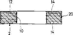
Usually comprise a stator and a rotor in outer-rotor type permanent magnet motor or the brush DC spindle motor, coil loop is twined around the tooth of a stator core, and the permanent magnet on the stator is radially facing to stator.As illustrated in fig. 1 and 2, the stator core 2 laminate core plate 4 that has annular shape and make by one group of silicon steel sheet.This iron core is to be made of a ring foundation part 6 and one group of tooth 8 that outwards stretches from foundation 6.Six teeth 8 are as an example along the circumferential direction with equidistant placement roughly, and centre bore 10 is formed in the middle body of foundation 6 and stretch along the stacked direction of plate 4 unshakable in one's determination.Stator core 2 is installed on a hollow circuit cylinder axle or the pillar part, promptly by cylinder axis is assemblied in the centre bore 10 (following centre bore 10 is known as installing hole), thereby constitutes a stationary parts of motor.
As shown in Figure 2, stator core 2 need be by an electric insulating film or a layer covering that has different-thickness in different piece unshakable in one's determination.That is to say, at the both sides end face 14 of foundation 6 and each tooth 8 and determine the electric insulating film at 18 places, surface of the groove 16 between the adjacent teeth 8 or outer surface 20 places that layer 12 should be thicker than each tooth 8, so that have electrical insulating property between coil that twines around each tooth 8 and the stator core 2, and stator core has antirust ability.On the other hand, wish that the thickness of electric insulating film 12 at outer surface 20 places of each tooth 8 determines surperficial 18 places less than foundation 6, each tooth 8 and groove, thus when making stator core 2 have antirust ability, make the tooth top periphery surface and the permanent magnet faced between the gap as far as possible little.For example, the thickness " T1 " of preferred electric insulating film 12 is at least 50 to 80 μ m, and should be 20 to 50 μ m at the both sides end face 14 of foundation 6 and each tooth 8 and the thickness " T2 " of electric insulating film 12 of determining 18 places, surface of the groove 16 between the adjacent teeth 8.
Also wish the foregoing same electrical insulation film 12 of spraying on the interior perimeter surface of the installing hole 10 of the foundation 6 of determining stator core 2.This electric insulating film 12 is used to make stator core 2 to have antirust ability, and can obtain buffering or damping to absorb or to reduce impact transmission between stator core 2 and the spindle unit.The thickness of wishing this film or layer equates with foregoing thickness " T1 ".
Please refer to Fig. 3 below, with the method for explanation this spray-coated film of acquisition in stator core 2, and the used maintenance anchor clamps that are used for clamping stator core 2 will be explained in the back in electrostatic power spraying apparatus and the spraying process.As shown in Figure 3, step 1 is the preprocessing process of stator core 2.In preprocessing process, be deposited on when the assembling of stator core 2 that stator core is lip-deep can be removed such as printing-ink and anticorrosion wet goods adherent before applying coating, so that do not damage the stability and the adherence of electric insulating film 12.In preprocessing process, the stator core 2 that has an adherent is stored in the container heating a scheduled time slot, controls temperature decomposing or the gasification adherent by hot gas convection current or infrared radiation in the container, and don't can make the core material oxidation.
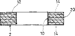
After step 1 finished, stator core 2 was cooled to room temperature and is transported to the station that is used for the first electrostatic powder coating process at step 2 place.In step 2, stator core 2 is displaced into that maintenance anchor clamps clamping in the electrostatic powder coating station and with keeping the rotation of anchor clamps monoblock type.Stator core 2 can be sprayed by the electrostatic powder coating device when mobile in the electrostatic powder coating station.After stator core 2 moves past the step 2 place station, have electric insulating film or the layer 12 that first predetermined thickness is 30 to 50 μ m on the almost whole surface of stator core 2 (the both sides end face 14 of stator core 2, groove are determined surface 18, the top perimeter surface 20 of tooth 8 and the interior perimeter surface of installing hole 10) is all coated, as shown in Figure 4.
After step 2, stator core 2 is transported to the station that is used for powder removal process at step 3 place and is held the anchor clamps clamping rotation.In step 3, stator core 2 is held the anchor clamps clamping and and rotate on together in the powder removal station.When stator core 2 was mobile in the powder removal station, the powder removal device that the spray-coated film on the outer surface 20 of the tooth of stator core 2 will be described was below removed.In step 3, as shown in Figure 5, the electric insulation spray-coated film 12 that only is positioned on the most peripheral surface 20 of each tooth 8 is removed, and other position of stator core 2 (the both sides end face 14 of stator core 2, groove are determined the interior perimeter surface of surface 18 and installing hole 10) then keeps their coating state.
After step 3, stator core 2 is transported to the station that is used for the second electrostatic powder coating process at step 4 place and is held the anchor clamps clamping rotation.In step 4, stator core 2 is held the anchor clamps clamping and and be displaced into together in the electrostatic powder coating station, identical in the structure of this station and processing procedure and the step 2.After step 4 finishes, has the electric insulating film 12 that second predetermined thickness is 20 to 50 μ m on the almost whole surface of stator core 2 (the both sides end face 14 of stator core 2, groove are determined surface 18, the top perimeter surface 20 of tooth 8 and the interior perimeter surface of installing hole 10) is all coated.
After step 4, as shown in Figure 2, determine that at the both sides of stator core 2 end face 14 and groove the thickness " T1 " of the electric insulating film 12 on the surface 18 is the film thickness sum that forms in the film thickness that forms in the first electrostatic powder coating process and the second electrostatic powder coating process, thereby this thickness is relatively large.Like this, determine to be coated with the electric insulating film 12 of thickness for " T1 " on the surface 18 at the both sides of stator core 2 end face 14 and groove, obtain enough electrical isolation capabilities thereby make around their coils, non-corrosive is then guaranteed on each surface.
On the other hand, as shown in Figure 2, the thickness " T2 " of the electric insulation spray-coated film 12 on the top perimeter surface 20 of tooth 8 is the film thickness that forms in the second electrostatic powder coating process, thereby this thickness is less relatively.Like this, coated on the most peripheral surface 20 of stator core 2 thickness is arranged is the electric insulating film 12 of " T2 ", to guarantee these surperficial non-corrosives, is coated with the zone of apposition thickness for the electric insulation spray-coated film 12 of " T1 " although their electrical isolation capabilities is lower than.After stator core is assembled in the motor, the less thickness " T2 " of the electric insulation spray-coated film 12 on the most peripheral surface 20 of tooth 8 can be guaranteed to reduce in the most peripheral surface 20 of spray-coated film inboard and the radial clearance between the magnet (not shown) inner surface, to reduce the magnetic resistance between stator and the magnet, so that motor obtains higher efficient with reduced size.
After step 4, stator core 2 is transported to the station that is used for first high-frequency heating process at step 5 place and is held the anchor clamps clamping rotation.In step 5, be held the anchor clamps clamping and rotational stator iron core 2 and will between the slippage coil of an existing heating generator, move.When stator core 2 was mobile between the slippage coil, stator core 2 was higher than room temperature greater than 20 to 40 seconds kinds of 150 ℃ of heating under an atmospheric pressure.When stator core 2 was heated after step 4 by this way, the particle that constitutes electric insulating film 12 can melt.
After step 5, stator core 2 is transported to the station that is used for first cooling procedure at step 6 place and is held the anchor clamps clamping rotation.In step 6, be held the anchor clamps clamping and rotational stator iron core 2 and can be cooled.The coating particles of the fusing in step 5 in the stator core 2 can be cooled to below the temperature of coating particles fusing point, thereby is cured, and is positioned at the lip-deep coating of stator core to form one.After cooling, compressed air blow to clamping stator core the maintenance anchor clamps and near, with remove adhesion more than powdery paints.
After step 6, stator core 2 also can be transported to step 7 place secondary high-frequency heating process the station and be held the anchor clamps clamping and rotation.In step 7, be held the anchor clamps clamping and rotational stator iron core 2 and move between will the slippage coil in being similar to step 5.Stator core 2 is heated to 20 to 40 seconds kinds of a temperature between 200 to 230 ℃ once more after step 6.After moving past the slippage coil, stator core 2 can be compressed air or hair-dryer through steps 8 (cooling procedure) and blow and force cool to room temperature, and adheres to can be removed simultaneously more than powdery paints in anchor clamps and the stator core 2.
After step 8, stator core 2 is transported to the station that is used for the back solidification process at step 9 place and is held the anchor clamps clamping rotation.In step 9, be held the anchor clamps clamping and rotational stator iron core 2 and will stand multiple processing.Stator core 2 can for example, make temperature rise to 240 ℃ in one minute, and keep this state three minutes under atmospheric pressure through being subject to processing after step 8, was reduced to room temperature again in seven minutes.Coating film in the stator core 2 or layer will have homogenizing after having stood multiple processing thickness, stabilized quality and good film thickness.After step 9, stator core 2 is taken off from the maintenance anchor clamps, thereby obtains the desirable stator core shown in Fig. 1 and 2.
Next, will be by explain the electrostatic power spraying apparatus that is used for implementation step 2 to 4 with reference to figure 6 to 9.Fig. 6 is the schematic diagram according to the electrostatic power spraying apparatus of the embodiment of the invention.Fig. 7 A, 7B are in the electrostatic power spraying apparatus shown in Figure 6 one front views that keeps anchor clamps, and wherein the first half has shown cross section and Lower Half has shown outward appearance.Fig. 8 is the part sectioned view of the state of stator core when being held the anchor clamps clamping.Fig. 9 A to 9C is the part sectioned view that shows when stator core is held anchor clamps clamping operation.
Electrostatic power spraying apparatus comprises one and keeps anchor clamps, conveying device, electrostatic powder coating device and powder removal device, as explaining in detail hereinafter.As shown in Figure 6, equipment comprises a main body 102, and it is installed on the floor or analog of factory.Sprayed the throughput direction of stator core in main body 102 upper edges, promptly direction shown in the arrow 104 is installed with one first electrostatic spraying district " A ", powder removal district " B " and one second an electrostatic spraying district " C ".In the first electrostatic spraying district " A " an electrostatic powder coating device 106 is housed, in order to the first electrostatic powder coating process in the performing step 2.Powder is removed in the district " B " powder removal device 108 is housed, and removes process in order to the powder in the performing step 3.In the two electrostatic spraying districts " C " electrostatic powder coating device 110 is housed, in order to the second electrostatic powder coating process in the performing step 4.
Corresponding electrostatic powder coating device 106 and 110 can have essentially identical each other structure among the first and second electrostatic powder coating districts " A " and " C ".Electrostatic powder coating device 106 and 110 is made of a triboelectric charging formula powder flush coater respectively, and powder particle is ejected into by on the spraying article in this machine, and is for example, disclosed such among the Japanese Laid-Open Patent Application No.10-145988.
Powder removal device 108 has a remover, and as a scraping blade or brush, it is used for, and for example, contacts with these article not stop by the mode of spraying article rotation.
Conveying device comprises the conveying screw rod of a pair of stretching, extension parallel to each other.This a pair of conveying screw rod along the first electrostatic spraying district " A ", the powder direction of removing the district " B " and the second electrostatic spraying district " C " is placed in the main body 102.When the rotation of a pair of conveying screw rod, stator core 2 in clamping and the maintenance anchor clamps 112 that are installed on the described screw rod can be moved by each direction that screw rod rotation drive along the first electrostatic spraying district " A ", powder is removed the district " B " and the second electrostatic spraying district " C ".Like this, along with stator core 2 is carried as described above, the processing in the performing step 2 and 4 as described above.After step 4, stator core 2 is held the anchor clamps clamping and and be transported to heating generator, with the processing in the implementation step 5.
Next, will be by explain the maintenance anchor clamps 112 that are used for clamping stator core 2 with reference to figure 7A, 7B, 7C and 8.Keep anchor clamps 112 to constitute by first and second anchor clamps that connecting with removably each other.
The other end (right side among Fig. 7 A to 8) at first cylindrical element 118 is being fixed a bar 134 that is used to carry first anchor clamps.At the opening of the through hole 120 of this other end that is arranged in cylindrical element 118, the internal diameter major part of an internal diameter greater than through hole 120 is shaped.On the circumferential surface of this internal diameter major part, a screw that radially penetrates is shaped.
A screw 136 is assemblied in this screw, lean outer surface by the end that makes screw 136 at the bar 134 that is used to carry, and an end (left side among Fig. 7 A to 8) that is used in the bar 134 of conveying is assemblied on the internal diameter major part of cylindrical element 118, the bar 134 that is used to carry can be fixed on cylindrical element 118.The bar 134 that is used to carry is by making such as conductive metallic materials such as brass.When being transferred screw and driving rotation, the bar 134 that is used to carry can move on conveying screw rod.
On the other hand, second anchor clamps 116 comprise one by second cylindrical element of making such as conducting metals such as brass 142.A through hole 142a who stretches vertically is formed in second cylindrical element 142.A radially screw of break-through cylindrical wall is shaped in the centre of second cylindrical element 142.End (right side among Fig. 7 A to 8) at second cylindrical element 142 is being fixed a connecting rod 144.A screw 146 is assemblied in the screw, leans on the outer surface of connecting rod 144 and connecting rod 144 is assemblied among the through hole 142a by the end that makes screw 146, connecting rod 144 can be fixed on second cylindrical element 142.Connecting rod 144 comprises a foundation that is used for being assembled to through hole 142a, diameter and partly stretches to terminal path end 152a greater than the hook agency part 148 of foundation, the tapering part 150 and the path from tapering part 150 that begin to attenuate from hook agency part 148.A crack 152 forms in the end of path end 152a vertically, thereby path end 152a prolongs slightly.In addition, connecting rod 144 can be configured as one with second cylindrical element 142.
Fixing one by the protection sleeve of making such as synthetic resin such as teflons 154 at an end of second cylindrical element 142, its protection sleeve 122 shapes with foregoing first anchor clamps 114 are identical.Second cylinder gripper specifically comprises second cylindrical element 142 and protection sleeve 154.Protection sleeve 154 is fixed on second cylindrical element 142, and its mode is identical with the mode that protection sleeve 122 is fixed on first cylindrical element 118.The hook agency part 148 of connecting rod 144 and path end 152a stretch out from an end (right side Fig. 7 A to 8) of protection sleeve 154, and stay enough intervals in the inner surface diameter of connecting rod 144 and protection sleeve 154.
Fixing a bar that is used to carry 156 at the other end of second cylindrical element 142, it is identical with the bar that is used to carry 134 shapes on foregoing first anchor clamps.Bar 156 is fixed on second cylindrical element 142, and its mode is identical with the mode that bar 134 is fixed on first cylindrical element 118.When being transferred screw and driving rotation, the bar 156 that is used to carry can move on conveying screw rod.
Next, will be by keeping the method for anchor clamps 112 clamping stator cores 2 to explain utilization with reference to figure 8 to 9C.To keep anchor clamps 112 clamping stator cores in order utilizing, shown in Fig. 9 A to 9C, to need to adopt an assembly fixture 162.Assembly fixture 162 comprise a long narrow shape be used for supporting the support body 164 that keeps anchor clamps 112 and stator core 2 and one be used for stator core 2 longitudinally (left and right directions of Fig. 8) remain on retaining part 166 on support body 164 top surfaces at middle position.Retaining part 166 comprises one and keeps recessed portion 168, and it is made of a pair of vertical wall 166a, and two walls are facing with each other and the interval between them or spacing equal to be held the thickness of stator core 2.The height of a pair of wall part 166a is to determine like this, and promptly the installing hole 10 of stator core 2 is uncovered when stator core 2 is held part 166 and is keeping.For retaining part 166, being shaped one on one side of support body 164 (right side of the retaining part 166 among Fig. 9 A to 9C) is used to guide the first support guide part 170 of first anchor clamps 114, is used to guide the second support guide part 172 of second anchor clamps 116 and be shaped on the opposite side one.
Before being held anchor clamps 112 clampings, stator core 2 is placed in earlier in the retaining part 166 of assembly fixture 162, shown in Fig. 9 A.The bottom of stator core 2 is contained in the retaining part 166, and installing hole 10 then is positioned on the retaining part 166.
Next, shown in Fig. 9 B, first anchor clamps 114 are placed on the first support guide part 170 that keeps anchor clamps 162, so that gripper hook 126 is facing to stator core 2.Afterwards, first anchor clamps 114 move along the first support guide part 170, lean on the retaining part 166 that is keeping anchor clamps 162 until protection sleeve 122.The hook portions 128 of one group of gripper hook 126 on first anchor clamps 114 is positioned to be held in the installing hole 10 of the stator core 2 that part 166 keeping, and hook portions 128 keeps loose fits with installing hole 10.
Interval that equates with the thickness of wall part 166a is specified between the end face of protection sleeve 122 of the end face (right side of the stator core 2 among Fig. 9 A to 9C) of stator core 2 and first anchor clamps 114.In addition, be slightly less than the internal diameter of the installing hole 10 of stator core 2 by a terminal determined imaginary diameter of a circle of the hook portions 128 of one group of gripper hook 126, therefore, when first anchor clamps 114 move to a predetermined occlusal position so that the end of first anchor clamps when touching stator core 2, these gripper hooks 126 can not touch stator core 2.
Next, shown in Fig. 9 C, second anchor clamps 116 are placed on the second support guide part 172 that keeps anchor clamps 162, so that connecting rod 144 is facing to stator core 2.Afterwards, second anchor clamps 116 move along the second support guide part 172, lean on the retaining part 166 that is keeping anchor clamps 162 until protection sleeve 154.The end of the connecting rod 144 of second anchor clamps 116 penetrates in the installing hole 10 that is held the stator core 2 that part 166 keeping and with installing hole and keeps loose fit.Afterwards, the end of the connecting rod 144 of second anchor clamps 116 moves into the imaginary circle of being determined and be arranged in installing hole 10 by one group of gripper hook 126, and insert in the through hole 120 of first anchor clamps 114 slightly this end.Meanwhile, the tapering part 150 of connecting rod 144 is leaning these gripper hooks 126, thereby along the external diameter direction diameter of a circle elasticity of being determined by gripper hook 126 is increased.In other words, gripper hook 126 is by resiliency urged and expansion radially outward.Like this, the hook portions 128 of these gripper hooks leans against elastic top on the inner surface of installing hole 10 of stator core 2.At this moment, has line between the end that has only each hook portions 128 and this inner surface or point contacts.
In addition; as shown in Figure 8; when second anchor clamps 116 move to when making its protection sleeve 154 with position that the retaining part 166 that keeps anchor clamps 162 leans mutually; the shaping of the end of connecting rod 144 makes that the both sides of slit 152 are that branch part slight radial outwards is offset, thereby the inner surface of through hole 120 can promote end so that end inside strain slightly radially.Like this, end is assemblied in the through hole 120 removably.Therefore, rotate at the volley even keep anchor clamps 112 clampings stator core 2, first and second anchor clamps 114 and 116 can be not disconnected from each other yet.
The hook agency part 148 of connecting rod 144 is leaning the part between hook portions 128 and middle body on the gripper hook 126, so that hook portions 128 is along the expansion of external diameter direction, with the position of definite and gripper hook subdivision 128.Like this, the hook portions 128 of one group of gripper hook 126 is maintained at such state, and promptly their elastic top are against the interior perimeter surface of the installing hole 10 of stator core 2.At this moment, interval that equates with the thickness of wall part 166a is specified between the end face of protection sleeve 154 of another end face of stator core 2 and second anchor clamps 116.
Being held stator core 2 that anchor clamps 112 clampings as previously mentioned can keep anchor clamps 112 and pull down from assembly fixture 162 by lifting upwards.At this moment, stator core 2 is held anchor clamps 112 clampings and but be not capped.Like this, stator core 2 be located in the electrostatic spraying device and be transported to ratio 2 make the station so that implement the first electrostatic powder coating process.
In the first and second electrostatic powder coating processes; charged powder or particulate coating material are injected into and are held as previously mentioned in the stator core 2 that anchor clamps 112 clampings; so that powdery paints not only can arrive the top perimeter surface 20 of both sides end face 14, the definite surface 18 of groove and each tooth 8; can also arrive the inner surface of installing hole 10; this is because installing hole 10 is not held anchor clamps 112 to be stopped up or cover, but leaves an interval between the end face of stator core 2 and the protection sleeve of maintenance anchor clamps.In addition, wish that this is spaced apart, for example, 1 to 2mm.By regulating the size at this interval, can regulate electric insulation spray-coated film or the layer 12 that is formed on the installing hole inner surface.
After above-mentioned steps 9 finished, stator core 2 was taken off from keep anchor clamps 112.A kind of be used for the method that keeps anchor clamps 112 to remove from stator core as described below.First and second anchor clamps 114 and 116 move and away from each other in opposite direction.After connecting rod 144 took off from gripper hook 126, the hook portions 128 of gripper hook 126 radially moved inward from the position of the inner surface of the installing hole 10 that leaning stator core 2, to return their initial position.Afterwards, stator core 2 breaks away from these gripper hooks 126 and can be along with further oppositely moving of first and second anchor clamps 114 and 116 from keeping anchor clamps 112 to take off.
In the present embodiment, keep at least one in the anchor clamps 112, for example, first anchor clamps 114 are ground connection by connecting spraying equipment main body 102.Like this, as being electrically connected conveying screw rod (spraying equipment main body 102) by one group of gripper hook 126, first cylindrical element 118 of ground connection and the bar 134 that is used to carry by the stator core 2 of spraying article, thus make charged particulate coating material can electrodeposition in stator core 2.In addition, if second anchor clamps 116 are by connecting spraying equipment main body 102 during ground connection, then stator core 2 is being electrically connected conveying screw rod (spraying equipment main body 102) by one group of gripper hook 126, connecting rod 144, second cylindrical element 142 of ground connection and the bar 156 that is used to carry.
The front has been described according to an embodiment who keeps anchor clamps and an electrostatic power spraying apparatus of the present invention.Yet scope of the present invention is not limited to this embodiment, but can make various changes and remodeling.
For example, among the described in front embodiment, the first and second electrostatic spraying districts " A " in the spraying equipment 102 and " C " are separated by along the article moving direction and are arranged on the spraying equipment 102.Yet, also can only on a position of spraying equipment, settle the electrostatic spraying district, can be moved into and shift out the electrostatic spraying district by the spraying article like this, to pass this spraying district twice.
In addition, among the described in front embodiment, adopted the stator core of motor to describe by the spraying article, wherein, therefore can change the quantity that powder spraying process or powder are removed process according to required different film thicknesses in the thickness difference of the zones of different spray-coated film of stator core or layer.On the other hand, when not needing different spray-coated film thickness, powder is removed process and the second powder spraying process can omit.
In addition, among the described in front embodiment, what sprayed the article employing is the iron core that constitutes stator.Yet article are not limited thereto, and the present invention also can be implemented on used recording disk fixed magnets in the driving arrangement of the magnet of iron core that electrostatic spraying constitutes rotor, motor or recording disk.Can also recognize, can be not limited to such motor part by being sprayed article, and can be any annular article that other need be sprayed at inner surface and outer surface.
Claims (20)
1. electrostatic power spraying apparatus, it is used for powder with static electrification and is sprayed on and has annular article of determining the inner surface of centre bore, and this equipment comprises:
One keeps anchor clamps, it comprises one first anchor clamps, described first anchor clamps have one group along the circular arrangement and the gripper hook of strain radially, and one second anchor clamps, described second anchor clamps have a bar, described first and second anchor clamps insert the centre bore of article and interlock each other from opposition side respectively, i.e. the described gripper hook of bar interlock is so that described hook strain and they are leaned on the inner surface of article; And
The electrostatic powder injector, it is used for powderject with static electrification to the annular article of by the clamping of above-mentioned maintenance anchor clamps.
2. electrostatic power spraying apparatus according to claim 1, it is characterized in that, each gripper hook has a hook portions respectively, the end of this hook portions is configured, feasible littler than the diameter of described centre bore by the determined imaginary diameter of a circle of described end, and described end leans on the inner surface of described article.
3. electrostatic power spraying apparatus according to claim 2 is characterized in that the end of described hook portions is sharp.
4. electrostatic power spraying apparatus according to claim 1 is characterized in that, described first anchor clamps comprise a hole, and it is used to receive the bar on described second anchor clamps, so that first and second anchor clamps are coupled together.
5. electrostatic power spraying apparatus according to claim 4, it is characterized in that, described first and second anchor clamps have an end face respectively, it is connected to each other and clamping can be facing to article when article at described anchor clamps, and described anchor clamps also comprise the device that is used for limiting their relative positions when described anchor clamps are in connection status, so that form at interval between described end face and article.
6. electrostatic power spraying apparatus according to claim 1 is characterized in that, it is concrete that described first anchor clamps comprise one first cylinder gripper; One group by having the gripper hook that electric conductivity and flexible material are made, and described gripper hook is arranged along the clamp body extending longitudinally and along an imaginary circle or cylinder; And a connecting hole, its end since first clamp body is shaped and is coaxial with one group of determined circle of gripper hook, and it is concrete that described second anchor clamps comprise one second cylinder gripper; And longitudinally extending bar-shaped connecting rod along second clamp body, this connecting rod has a first, it is used to insert connecting hole, and second portion, it is used for the described gripper hook of interlock so that latter's strain and they are contacted with the article inner surface, thereby clamps article.
7. electrostatic power spraying apparatus according to claim 1 is characterized in that, also comprises a conveyer, is used to carry be held the annular article that the anchor clamps clamping and pass through electrostatic sprayers.
8. electrostatic power spraying apparatus according to claim 7 is characterized in that, also comprises sprayed coating and removes the station, and it is used for removing the film that injected device is sprayed on the specific region of annular article; And one second injector, it is used for powderject with static electrification to annular article, described first and second anchor clamps have one respectively and are transferred the carriage that machine is supporting, and be transferred the machine conveying so that the anchor clamps of article in clamping, and anchor clamps can rotate with article are whole together.
9. electrostatic power spraying apparatus according to claim 1, it is characterized in that, injector comprises first spray equipment, it is used at first powderject with static electrification to annular article, and second spray equipment, it is used for subsequently powderject with static electrification to annular article, and also comprises a spray-coated film removal device in this electrostatic power spraying apparatus, and it is used for removing the sprayed coating first time of article specific region before spraying for the second time.
10. electrostatic power spraying apparatus according to claim 1 is characterized in that, described electrostatic powder injector comprises:
One the first electrostatic spraying station, it is used for powderject with static electrification to the annular article of by the clamping of described maintenance anchor clamps;
A sprayed coating is removed the station, and it is used for removing the powder bed that is positioned at a specific region on the annular article that sprays in the first electrostatic spraying station;
One the second electrostatic spraying station, it is used for the powderject of static electrification to the local annular article of having removed first sprayed coating; And
A conveyer, it is used for articles conveyed by the described first and second electrostatic spraying stations and the described sprayed coating removal station.
11. electrostatic power spraying apparatus according to claim 1, it is characterized in that, described annular article are stator core used in the motor, and described stator core has the ring foundation part and the one group of tooth that radially outward stretches from foundation that have the inner surface of determining a centre bore.
12. one kind keeps anchor clamps, it is used for clamping and has annular article of determining the inner surface of centre bore, and these article then will stand a kind of processing, it is characterized in that, described maintenance anchor clamps comprise:
One first anchor clamps, it has one group along the circular arrangement and the gripper hook of strain radially, and each described hook has a sharp end that radially outward stretches respectively, and
One second anchor clamps, it has a bar, and described first and second anchor clamps insert the centre bore of article and interlock each other from opposition side respectively, i.e. and the described gripper hook of bar interlock is so that described hook strain and they are leaned on the inner surface of article.
13. maintenance anchor clamps according to claim 12 is characterized in that, described first anchor clamps comprise a hole, and it is used to receive the bar on described second anchor clamps, so that described first and second anchor clamps are coupled together.
14. maintenance anchor clamps according to claim 13 is characterized in that, it is concrete that described first anchor clamps comprise one first cylinder gripper; One group by having the gripper hook that electric conductivity and flexible material are made, and described gripper hook is arranged along the clamp body extending longitudinally and along an imaginary circle or cylinder; And a connecting hole, its end since first clamp body is shaped and is coaxial with one group of determined circle of gripper hook, and it is concrete that second anchor clamps comprise one second cylinder gripper; And longitudinally extending bar-shaped connecting rod along second clamp body, this connecting rod has a first, it is used to insert connecting hole, and second portion, it is used for the described gripper hook of interlock so that latter's strain and they are contacted with the article inner surface, thereby clamps article.
15 maintenance anchor clamps according to claim 12, it is characterized in that, described annular article are stator core used in the motor, and described stator core has an inner surface of determining a centre bore, and described stator core then will be gone up the powder of static electrification by spraying.
16. one kind is used for the method for electrostatic powder coating on annular article, described annular article have an inner surface of determining a centre bore, it is characterized in that, this method comprises following each step:
The end of one group of resilient clamp hook in one first anchor clamps from annular article inserted the centre bore of annular article;
One second anchor clamps are inserted so that in second anchor clamps and the described gripper hook interlock from the direction opposite with first anchor clamps, thereby make described gripper hook touch the inner surface of annular article, clamp annular article to utilize first and second anchor clamps; And
Charged powder coating is injected on the annular article of by the first and second anchor clamps clampings.
17. electrostatic powder coating method according to claim 16 is characterized in that also comprising following steps: first and second anchor clamps are joined to one another, so that described gripper hook is supporting article.
18. electrostatic powder coating method according to claim 17 is characterized in that also comprising following steps: remove the spray-coated film in the specific region after spraying on the whole surface at annular article; And the whole surface that sprays annular article once more, so that the spray-coated film thickness difference in the zones of different of annular article.
19. electrostatic powder coating method according to claim 16, it is characterized in that, described annular article are stator cores that are used for motor, the powder of spraying static electrification on it, described stator core comprises the ring foundation part and the one group of tooth along stretching, extension of external diameter direction and equidistant placement that have the centre bore of being determined by inner surface, and described injecting step comprises:
Charged powder coating is injected on the whole surface of the stator core of by the anchor clamps clamping:
After the whole surface of annular article is sprayed, the lip-deep spray-coated film of the most peripheral of each tooth is removed; And
Spray the whole surface of annular article once more, so that the spray-coated film on the outer surface of each tooth is different with other lip-deep spray-coated film thickness of stator core.
20. electrostatic powder coating method according to claim 16, it is characterized in that, described annular article are stator cores that are used for motor, the powder of spraying static electrification on it, described stator core comprises the ring foundation part and the one group of tooth along stretching, extension of external diameter direction and equidistant placement that have the centre bore of being determined by inner surface, and described injecting step comprises:
The stator core that conveying by described anchor clamps clamping is used to remove second station and the 3rd station that is used for spraying once more the whole surface of stator core of the coating on the outermost part of tooth of stator core by first station that is used to spray the whole surface of stator core, one.
Applications Claiming Priority (2)
| Application Number | Priority Date | Filing Date | Title |
|---|---|---|---|
| JP153160/1999 | 1999-06-01 | ||
| JP15316099A JP3501395B2 (en) | 1999-06-01 | 1999-06-01 | Electrostatic powder coating equipment |
Publications (2)
| Publication Number | Publication Date |
|---|---|
| CN1276269A CN1276269A (en) | 2000-12-13 |
| CN1110373C true CN1110373C (en) | 2003-06-04 |
Family
ID=15556361
Family Applications (1)
| Application Number | Title | Priority Date | Filing Date |
|---|---|---|---|
| CN00109025A Expired - Lifetime CN1110373C (en) | 1999-06-01 | 2000-06-01 | Apparatus and method for spraying annular objects and holder for holding the same |
Country Status (3)
| Country | Link |
|---|---|
| US (1) | US6322629B1 (en) |
| JP (1) | JP3501395B2 (en) |
| CN (1) | CN1110373C (en) |
Families Citing this family (19)
| Publication number | Priority date | Publication date | Assignee | Title |
|---|---|---|---|---|
| JP4893902B2 (en) * | 2001-03-21 | 2012-03-07 | 株式会社一宮電機 | Ring jig holding jig, set jig and punching jig, and electrostatic powder coating method using them |
| DE10333187A1 (en) * | 2003-07-22 | 2005-03-03 | Robert Bosch Gmbh | Method for applying an electrical insulation |
| US7342334B2 (en) * | 2004-10-29 | 2008-03-11 | Emerson Electric Co. | Insulated stator with wire routing element |
| US7981465B2 (en) * | 2007-01-16 | 2011-07-19 | Globe Motors, Inc. | Method and apparatus for powder coating stator stacks |
| DE102008054810A1 (en) * | 2008-12-17 | 2010-06-24 | Robert Bosch Gmbh | Method for removing an electrically insulating powder layered on a stator iron, device for carrying out the method and electric machine with a stator iron |
| CN103023238B (en) * | 2012-11-28 | 2015-04-08 | 芜湖杰诺瑞汽车电器系统有限公司 | Generator stator winding paint dipping clamp |
| CN103263995B (en) * | 2013-05-08 | 2016-08-03 | 创斯达(南通)机电有限公司 | A kind of device for round piece spraying |
| CN103707203B (en) * | 2013-12-11 | 2016-08-17 | 中原内配集团股份有限公司 | Cylinder jacket sandblasting, spraying frock clamp |
| CN103785577B (en) * | 2014-01-17 | 2016-02-10 | 上海宇田机电设备有限公司 | A kind of bottle cap rubber-coated mechanism |
| CN104437935A (en) * | 2014-12-03 | 2015-03-25 | 贵州长征中压开关设备有限公司 | Device for spraying annular workpiece |
| CN104668130B (en) * | 2015-03-23 | 2017-07-28 | 浙江华立智能装备股份有限公司 | A kind of coating tool structure |
| DE102015225758A1 (en) | 2015-12-17 | 2017-06-22 | Robert Bosch Gmbh | Process for coating an electromagnetically excitable core |
| CN105537032B (en) * | 2016-02-02 | 2018-02-06 | 宿州市冠星金属制品制造有限公司 | A kind of annular one side coated steel belt frock |
| CN109622272B (en) * | 2018-12-17 | 2020-04-07 | 綦江县桥兴齿轮有限公司 | Gear device that oils |
| CN110052366B (en) * | 2019-05-13 | 2024-04-30 | 成都金士力科技有限公司 | Rotary glue filling equipment and method for high-low temperature vacuum stepper motor |
| CN110841817A (en) * | 2019-12-12 | 2020-02-28 | 中冶京诚工程技术有限公司 | Nozzle for powder spraying device and powder spraying device |
| CN113037034B (en) * | 2021-02-24 | 2022-07-29 | 北京航天控制仪器研究所 | Iron core hot dipping coating tool, system and method |
| CN114210519B (en) * | 2021-12-20 | 2022-10-18 | 宁波金坦磁业有限公司 | Automatic change coating equipment |
| CN120896399A (en) * | 2025-07-25 | 2025-11-04 | 东莞市益铁金属制品有限公司 | Fixtures and methods for electrostatic powder coating of motor cores |
Citations (2)
| Publication number | Priority date | Publication date | Assignee | Title |
|---|---|---|---|---|
| US3311085A (en) * | 1965-05-10 | 1967-03-28 | Millard F Smith | Apparatus for coating objects |
| US5540776A (en) * | 1991-02-27 | 1996-07-30 | Axis Usa, Inc. | Apparatus for applying a powdered coating to a workpiece |
Family Cites Families (5)
| Publication number | Priority date | Publication date | Assignee | Title |
|---|---|---|---|---|
| JPS60193560A (en) | 1984-03-15 | 1985-10-02 | Nippon Denko Kk | Device for rotating and moving material to be painted in automatic electrostatic painting machine |
| JPS6413573A (en) | 1987-07-08 | 1989-01-18 | Ricoh Kk | Image forming device |
| JP3434426B2 (en) | 1996-11-05 | 2003-08-11 | 株式会社田中製作所 | Motor core, motor provided with the motor core and jig for coating the core |
| JP3466837B2 (en) | 1996-11-05 | 2003-11-17 | 株式会社田中製作所 | Motor core and motor provided with the same |
| JP2987619B2 (en) | 1997-06-11 | 1999-12-06 | 株式会社英布 | Electrostatic powder coating equipment |
-
1999
- 1999-06-01 JP JP15316099A patent/JP3501395B2/en not_active Expired - Fee Related
-
2000
- 2000-05-31 US US09/584,383 patent/US6322629B1/en not_active Expired - Fee Related
- 2000-06-01 CN CN00109025A patent/CN1110373C/en not_active Expired - Lifetime
Patent Citations (2)
| Publication number | Priority date | Publication date | Assignee | Title |
|---|---|---|---|---|
| US3311085A (en) * | 1965-05-10 | 1967-03-28 | Millard F Smith | Apparatus for coating objects |
| US5540776A (en) * | 1991-02-27 | 1996-07-30 | Axis Usa, Inc. | Apparatus for applying a powdered coating to a workpiece |
Also Published As
| Publication number | Publication date |
|---|---|
| JP3501395B2 (en) | 2004-03-02 |
| US6322629B1 (en) | 2001-11-27 |
| JP2000334336A (en) | 2000-12-05 |
| CN1276269A (en) | 2000-12-13 |
Similar Documents
| Publication | Publication Date | Title |
|---|---|---|
| CN1110373C (en) | Apparatus and method for spraying annular objects and holder for holding the same | |
| CN101145717B (en) | Method and device for installing magnets | |
| CN111968849B (en) | A device and method for improving the coercive force of annular NdFeB magnets | |
| EP3029693A1 (en) | Method of bonding nd-fe-b permanent magnets | |
| US3355310A (en) | Method of forming layers of insulating material in slots of magnetic cores | |
| US6261403B1 (en) | Method for preventing bubbles or small bubbles when connecting substrate parts of optical data carriers by means of an adhesive | |
| JP2780017B2 (en) | Electrostatic powder coating equipment | |
| CN103072813A (en) | Device and method for automatic arrangement of laminated pieces of small-sized motor | |
| JP4191764B2 (en) | Method for applying an electrically insulating member | |
| CN110350733B (en) | Motor rotor permanent magnet attachment system | |
| US20170047832A1 (en) | Electric Motor and Process for Making an Electric Motor | |
| CN108654901A (en) | A kind of coating system and apply its workmanship of spraying plastics | |
| CN109660089B (en) | Automatic assembly process for permanent magnet motor stator | |
| JP2012110190A (en) | Stator core, method for manufacturing the same, and masking jig used for method for manufacturing the same | |
| JP2013183537A (en) | Rotor of permanent magnet type motor, and method of manufacturing the same | |
| JP7308351B2 (en) | Method for manufacturing stator for rotating electrical machine, stator for rotating electrical machine, and rotating electrical machine | |
| FR2754104A1 (en) | DEMAGNETIZATION PROCESS FOR ELECTRO-PERMANENT DEVICES | |
| AU2014317744A1 (en) | Synchronous electric machines | |
| FR2794053A1 (en) | MAGNETIC TRAY FOR FIXING MOLDS ON INJECTION MACHINES | |
| JP2936194B2 (en) | Core insulation method for rotating electrical machines | |
| US20230216382A1 (en) | Varnish applicator for electric motor | |
| RU2516266C2 (en) | Method for isolation of magnet core slots in motor armature | |
| CN203173441U (en) | Device for automatically arraying small electromotor laminated sheets | |
| CN207426828U (en) | Stator structure and motor with it | |
| JP5405179B2 (en) | Desorption device for masking jig for electrodeposition coating |
Legal Events
| Date | Code | Title | Description |
|---|---|---|---|
| C10 | Entry into substantive examination | ||
| SE01 | Entry into force of request for substantive examination | ||
| C06 | Publication | ||
| PB01 | Publication | ||
| C14 | Grant of patent or utility model | ||
| GR01 | Patent grant | ||
| CX01 | Expiry of patent term | ||
| CX01 | Expiry of patent term |
Granted publication date: 20030604 |