CN111037262B - Press mounting system - Google Patents
Press mounting system Download PDFInfo
- Publication number
- CN111037262B CN111037262B CN201911413742.6A CN201911413742A CN111037262B CN 111037262 B CN111037262 B CN 111037262B CN 201911413742 A CN201911413742 A CN 201911413742A CN 111037262 B CN111037262 B CN 111037262B
- Authority
- CN
- China
- Prior art keywords
- press
- frame
- fitting
- mounting
- pressure equipment
- Prior art date
- Legal status (The legal status is an assumption and is not a legal conclusion. Google has not performed a legal analysis and makes no representation as to the accuracy of the status listed.)
- Active
Links
Images


Classifications
-
- B—PERFORMING OPERATIONS; TRANSPORTING
- B23—MACHINE TOOLS; METAL-WORKING NOT OTHERWISE PROVIDED FOR
- B23P—METAL-WORKING NOT OTHERWISE PROVIDED FOR; COMBINED OPERATIONS; UNIVERSAL MACHINE TOOLS
- B23P19/00—Machines for simply fitting together or separating metal parts or objects, or metal and non-metal parts, whether or not involving some deformation; Tools or devices therefor so far as not provided for in other classes
- B23P19/02—Machines for simply fitting together or separating metal parts or objects, or metal and non-metal parts, whether or not involving some deformation; Tools or devices therefor so far as not provided for in other classes for connecting objects by press fit or for detaching same
- B23P19/027—Machines for simply fitting together or separating metal parts or objects, or metal and non-metal parts, whether or not involving some deformation; Tools or devices therefor so far as not provided for in other classes for connecting objects by press fit or for detaching same using hydraulic or pneumatic means
Abstract
The invention discloses a press mounting system, which is characterized in that: including base, pressure equipment frame, wherein the pressure equipment frame is arranged in on the base, be provided with first linear guide rail on the base, it is provided with pressure equipment anchor clamps layer board to slide on this first linear guide rail, first linear guide rail extends to pressure equipment frame below, be provided with first lead screw nut mechanism on the base, on the pressure equipment frame for all be provided with first pressure equipment mechanism on the preceding, the back of pressure equipment anchor clamps layer board direction of motion, the top surface of pressure equipment frame is provided with second pressure equipment mechanism, wherein second pressure equipment mechanism includes a plurality of pressure equipment heads along same slide rail horizontal slip, wherein the direction of motion of pressure equipment head with the direction of motion of pressure equipment anchor clamps layer board is perpendicular. The invention has the advantages of realizing multi-position automatic press mounting in a horizontal plane and a vertical plane, along with high working efficiency, high automation degree, labor saving and strong adaptability of the press mounting system.
Description
Technical Field
The invention relates to the field of press-fitting equipment, in particular to a press-fitting system.
Background
In the press fitting equipment in the prior art, the structure curing function is single, the corresponding bushing press fitting clamp can only be developed aiming at a single product, then the clamp is placed on a press for independent press fitting, the production efficiency is low, the application range of the press fitting clamp is narrow, especially, multiple groups of press fitting equipment are required to be used in different models of products of the same type, and the universality is not strong.
Disclosure of Invention
Aiming at the defects in the prior art, the invention aims to provide a press-fitting system which can realize simultaneous press-fitting in two directions in a horizontal plane and a vertical plane and independent press-fitting in two directions in the horizontal plane or the vertical plane, can adjust different press-fitting positions and is suitable for press-fitting of parts with various shapes and sizes.
In order to achieve the purpose, the invention adopts the following technical scheme:
a press fitting system is characterized in that: the press mounting device comprises a base and a press mounting frame, wherein the press mounting frame is arranged on the base, a first linear guide rail is arranged on the base, a press mounting fixture supporting plate is arranged on the first linear guide rail in a sliding mode, the first linear guide rail extends to the lower portion of the press mounting frame, a first lead screw nut mechanism for driving the press mounting fixture supporting plate to move horizontally along the first linear guide rail is arranged on the base, a first press mounting mechanism is arranged on the press mounting frame relative to the front and the back of the movement direction of the press mounting fixture supporting plate, a second press mounting mechanism is arranged on the top surface of the press mounting frame, the second press mounting mechanism comprises a plurality of press mounting heads which horizontally slide along the same sliding rail, and the movement direction of the press mounting heads is perpendicular to the movement direction of the press mounting fixture supporting plate.
Further, the electric cabinet control device further comprises an electric cabinet arranged at the rear part of the base and a control console arranged on one side of the base, wherein the control console is in control connection with the electric cabinet.
Further, the first press-fitting mechanism comprises a sliding frame horizontally arranged on the press-fitting frame, two ends of the sliding frame are connected to a group of stand columns of the press-fitting frame in a sliding mode, a press-fitting movable plate is horizontally arranged on the sliding frame in a sliding mode, a first ejector rod is arranged on the press-fitting movable plate, the first ejector rod is arranged behind the press-fitting movable plate, the front end of the first ejector rod penetrates through the press-fitting movable plate, and a horizontal electric cylinder pressure head or a hydraulic cylinder pressure head is connected to the front end of the first ejector rod.
Further, a second lead screw and nut mechanism for driving the sliding frame to vertically move is arranged on the press mounting frame; and a third lead screw nut mechanism for driving the press-fitting moving plate to horizontally move is arranged on the sliding frame.
Further, the second press-fitting mechanism further comprises a lifting frame, the lifting frame is lifted at the top of the press-fitting frame, the sliding rail is mounted on the lifting frame, the press-fitting head is connected to the sliding rail in a sliding mode through the press-fitting moving frame, and a sliding block is arranged on the press-fitting moving frame and is in sliding fit with the sliding rail.
Furthermore, a fourth screw-nut mechanism for driving the press-fitting moving frame to horizontally slide is arranged on the hoisting frame.
Furthermore, a second ejector rod is arranged on the press-fitting moving frame, a guide frame is arranged on the lower portion of the press-fitting moving frame, an extension rod is arranged on the guide frame, the upper end of the extension rod is connected with the second ejector rod, and the lower end of the extension rod penetrates through the guide frame and then is connected with the press-fitting head.
Further, the guide frame comprises a connecting plate, a guide rod, a connecting sleeve and a guide sleeve, wherein the guide sleeve is arranged at the lower part of the press-fitting moving frame; the upper end of the guide rod is arranged in the guide sleeve in a matching way, and the lower part of the guide rod is connected with the connecting plate; the connecting sleeve is arranged in the middle of the connecting plate; the lower part of the extension rod penetrates through the connecting sleeve and is fixedly connected with the connecting sleeve.
Furthermore, the bottom of the pressing fixture supporting plate is connected with a sliding block which is arranged on the first linear guide rail in a matching mode, positioning columns are arranged at two ends of the top surface of the pressing fixture supporting plate, and a plurality of raised supporting plates are arranged in the middle of the top surface of the pressing fixture supporting plate.
The invention has the advantages of realizing multi-position press mounting in a horizontal plane or a vertical plane, having high working efficiency, high automation degree, labor saving and strong adaptability of the press mounting system, and realizing horizontal press mounting and vertical press mounting of different parts with different sizes.
Drawings
FIG. 1 is a schematic structural view of the present invention;
FIG. 2 is a schematic structural view of a first press-fitting mechanism according to the present invention;
FIG. 3 is a schematic structural view of a second press-fitting mechanism in the present invention;
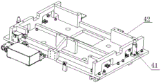
fig. 4 is a schematic structural view of a press-fitting jig pallet in the embodiment of the present invention.
Detailed Description
The present invention will be described in further detail with reference to the following embodiments and the accompanying drawings.
A press-fitting system as shown in fig. 1-4, comprising a base 1 and a press-fitting frame 2, wherein the press-fitting frame 2 is arranged on the base 1. The base 1 is provided with a first linear guide rail 3 extending from front to back along the base 1. The first linear guide rail 3 is provided with a press-fitting fixture supporting plate 4 in a sliding manner, the first linear guide rail 3 extends to the lower part of the press-fitting frame 2, so that the press-fitting fixture supporting plate 4 can move to the lower part of the press-fitting frame 2, and the base 1 is provided with a first lead screw and nut mechanism 5 for driving the press-fitting fixture supporting plate 4 to horizontally move along the first linear guide rail 3. The front and the back of the press-fitting frame 2 relative to the moving direction of the press-fitting clamp supporting plate 4 are provided with first press-fitting mechanisms 6; and a second press-fitting mechanism 8 is arranged on the top surface of the press-fitting frame 2. The second press-fitting mechanism 8 comprises a plurality of press-fitting heads 9 which horizontally slide along the same slide rail, wherein the moving direction of the press-fitting heads 9 is vertical to the moving direction of the press-fitting fixture supporting plate 4.
The press-fitting system disclosed by the invention is an automatic press-fitting system, and therefore, the press-fitting system further comprises an electrical cabinet 10 arranged at the rear part of the base 1 and a control console 11 arranged on one side of the base 1, wherein the control console 11 is in control connection with the electrical cabinet 10. The console 11 comprises a human-computer interaction interface for setting parameters of the press-fitting system.
In the embodiment of the present invention shown in fig. 1 and 2, the first press-fitting mechanism 6 includes a carriage 61 horizontally disposed on the press-fitting frame 2, and both ends of the carriage 61 are slidably connected to a set of columns of the press-fitting frame 2 through a linear slider mechanism, and the set of columns should be located in front of or behind the press-fitting frame 2. The sliding frame 61 is provided with a press mounting moving plate 62 through a linear guide rail sliding block mechanism in a horizontal sliding mode. The press-mounting frame 2 is provided with a second lead screw and nut mechanism 65 for driving the sliding frame 61 to vertically move; the carriage 61 is provided with a third lead screw and nut mechanism for driving the press-fitting moving plate 62 to move horizontally. The press-fitting moving plate 62 is provided with a first push rod 63, the first push rod 63 is an electric push rod or a hydraulic push rod, preferably, an electric push rod in the embodiment, the first push rod 63 is arranged behind the press-fitting moving plate 62, and the front end of the first push rod passes through the press-fitting moving plate 62. The front end of the first ejector rod 63 is connected with a horizontal electric cylinder pressure head 64. The first ejector rod 63 drives the horizontal electric cylinder pressing head 64 to move forwards to realize press mounting. In actual work, the first press-fitting mechanisms 6 positioned on the front and rear surfaces of the press-fitting frame 2 act synchronously and can mutually support to press-fit the front and rear sides of the workpiece simultaneously.
As shown in fig. 3, the second press-fitting mechanism 8 further includes a hoisting frame 81, and the hoisting frame 81 is hoisted to the top of the press-fitting frame 2. The slide rail is installed on the hoisting frame 81, the two press-fitting heads 9 are respectively connected to the slide rail in a sliding manner through the press-fitting moving frame 82, and a slide block is arranged on the press-fitting moving frame 82 and is in sliding fit with the slide rail. The hoisting frame 81 is provided with a fourth screw and nut mechanism 83 for driving the press-fitting movable frame 82 to horizontally slide, and the press-fitting movable frames 82 corresponding to the two press-fitting heads 9 are respectively and independently provided with the fourth screw and nut mechanism 83. The press-fitting moving frame 82 is provided with a second ejector rod 86, the second ejector rod 86 is an electric ejector rod or a hydraulic ejector rod, preferably, an electric ejector rod in this embodiment, the lower portion of the press-fitting moving frame 82 is provided with a guide frame 84, and the guide frame 84 is provided with an extension rod 85. The upper end of the extension rod 85 is connected with the second top rod 86, and the lower end of the extension rod passes through the guide frame 84 and then is connected with the press-fitting head 9. The guide frame 84 comprises a connecting plate 841, a guide rod 842, a connecting sleeve 843 and a guide sleeve 844, wherein the guide sleeve 844 is arranged at the lower part of the press-fitting movable frame 82; the upper end of the guide rod 842 is arranged in the guide sleeve 844 in a matching way, and the lower part of the guide rod 842 is connected with the connecting plate 841; the connecting sleeve 843 is arranged in the middle of the connecting plate 843; the lower part of the extension rod 85 penetrates through the connecting sleeve 843 and is fixedly connected with the connecting sleeve 843. The guide frame 84 is used for keeping the rigidity and the movement track of the extension rod 85 from deviating.
As shown in fig. 4, the bottom of the pressing fixture supporting plate 4 in this embodiment is connected with a sliding block, and the sliding block is fittingly arranged on the first linear guide rail. Positioning columns 41 are arranged at two ends of the top surface of the pressing fixture supporting plate 4, a plurality of raised supporting plates 42 are arranged in the middle of the top surface of the pressing fixture supporting plate, and the pressing fixture is placed on the supporting plates 42 and is positioned through the positioning columns 41. The press mounting system can be used by replacing various clamps, and has wide application range and high equipment utilization rate.
The technical solutions provided by the embodiments of the present invention are described in detail above, and the principles and embodiments of the present invention are explained herein by using specific examples, and the descriptions of the embodiments are only used to help understanding the principles of the embodiments of the present invention; meanwhile, for a person skilled in the art, according to the embodiments of the present invention, there may be variations in the specific implementation manners and application ranges, and in summary, the content of the present description should not be construed as a limitation to the present invention.
Claims (8)
1. A press fitting system is characterized in that: the press-mounting device comprises a base (1) and a press-mounting frame (2), wherein the press-mounting frame (2) is arranged on the base (1), a first linear guide rail (3) is arranged on the base (1), a press-mounting clamp supporting plate (4) is arranged on the first linear guide rail (3) in a sliding manner, the first linear guide rail (3) extends to the lower part of the press-mounting frame (2), a first lead screw nut mechanism (5) for driving the press-mounting clamp supporting plate (4) to horizontally move along the first linear guide rail (3) is arranged on the base (1), first press-mounting mechanisms (6) are arranged on the front and rear surfaces of the press-mounting frame (2) relative to the movement direction of the press-mounting clamp supporting plate (4), each first press-mounting mechanism (6) comprises a sliding frame (61) horizontally arranged on the press-mounting frame (2), and two ends of each sliding frame (61) are connected to a group of stand columns of the press-mounting frame (2) in a sliding manner, the horizontal sliding is provided with a press mounting moving plate (62) on the sliding frame (61), a first ejector rod (63) is arranged on the press mounting moving plate (62), the first ejector rod (63) is arranged behind the press mounting moving plate (62), the front end of the first ejector rod (63) penetrates through the press mounting moving plate (62), a horizontal electric cylinder pressure head (64) is connected to the front end of the first ejector rod (63), a second press mounting mechanism (8) is arranged on the top surface of the press mounting frame (2), the second press mounting mechanism (8) comprises a plurality of press mounting heads (9) which horizontally slide along the same sliding rail, and the moving direction of the press mounting heads (9) is perpendicular to the moving direction of the press mounting clamp supporting plate (4).
2. A press-fitting system according to claim 1, wherein: the device is characterized by further comprising an electrical cabinet (10) arranged at the rear part of the base (1) and a control console (11) arranged on one side of the base (1), wherein the control console (11) is in control connection with the electrical cabinet (10).
3. A press-fitting system according to claim 1, wherein: a second lead screw and nut mechanism (65) for driving the sliding frame (61) to vertically move is arranged on the press mounting frame (2); and a third lead screw and nut mechanism for driving the press-fitting moving plate (62) to horizontally move is arranged on the sliding frame (61).
4. A press-fitting system according to claim 1, wherein: the second press-fitting mechanism (8) further comprises a hoisting frame (81), the hoisting frame (81) is hoisted at the top of the press-fitting frame (2), the slide rail is installed on the hoisting frame (81), the press-fitting head (9) is connected onto the slide rail in a sliding mode through the press-fitting moving frame (82), a slide block is arranged on the press-fitting moving frame (82), and the slide block is in sliding fit with the slide rail.
5. A press-fitting system according to claim 4, wherein: and a fourth lead screw nut mechanism (83) for driving the press-fitting moving frame (82) to horizontally slide is arranged on the hoisting frame (81).
6. A press-fitting system according to claim 4, wherein: set up second ejector pin (86) on pressure equipment moving rack (82), pressure equipment moving rack (82) lower part has leading truck (84), be provided with extension rod (85) on leading truck (84), this extension rod (85) upper end with second ejector pin (86) are connected, and its lower extreme passes connect behind leading truck (84) pressure equipment head (9).
7. A press-fitting system according to claim 6, wherein: the guide frame (84) comprises a connecting plate (841), a guide rod (842), a connecting sleeve (843) and a guide sleeve (844), wherein the guide sleeve (844) is arranged at the lower part of the press-fitting moving frame (82); the upper end of the guide rod (842) is arranged in the guide sleeve (844) in a matching way, and the lower part of the guide rod is connected with the connecting plate (841); the connecting sleeve (843) is arranged in the middle of the connecting plate; the lower part of the extension rod (85) penetrates through the connecting sleeve (843) and is fixedly connected with the connecting sleeve (843).
8. A press-fitting system according to claim 1, wherein: the bottom of the press-fitting fixture supporting plate (4) is connected with a sliding block which is arranged on the first linear guide rail (3) in a matching mode, positioning columns (41) are arranged at two ends of the top surface of the press-fitting fixture supporting plate (4), and a plurality of raised supporting plates (42) are arranged in the middle of the top surface of the press-fitting fixture supporting plate.
Priority Applications (1)
| Application Number | Priority Date | Filing Date | Title |
|---|---|---|---|
| CN201911413742.6A CN111037262B (en) | 2019-12-31 | 2019-12-31 | Press mounting system |
Applications Claiming Priority (1)
| Application Number | Priority Date | Filing Date | Title |
|---|---|---|---|
| CN201911413742.6A CN111037262B (en) | 2019-12-31 | 2019-12-31 | Press mounting system |
Publications (2)
| Publication Number | Publication Date |
|---|---|
| CN111037262A CN111037262A (en) | 2020-04-21 |
| CN111037262B true CN111037262B (en) | 2021-10-08 |
Family
ID=70242721
Family Applications (1)
| Application Number | Title | Priority Date | Filing Date |
|---|---|---|---|
| CN201911413742.6A Active CN111037262B (en) | 2019-12-31 | 2019-12-31 | Press mounting system |
Country Status (1)
| Country | Link |
|---|---|
| CN (1) | CN111037262B (en) |
Families Citing this family (1)
| Publication number | Priority date | Publication date | Assignee | Title |
|---|---|---|---|---|
| CN112756942B (en) * | 2020-12-31 | 2022-04-08 | 无锡灵德自动化科技有限公司 | High-intelligent servo press-mounting machine |
Citations (9)
| Publication number | Priority date | Publication date | Assignee | Title |
|---|---|---|---|---|
| WO2005115684A1 (en) * | 2004-05-25 | 2005-12-08 | Honda Motor Co., Ltd. | Installation apparatus for piston ring |
| CN201800252U (en) * | 2010-08-18 | 2011-04-20 | 张宝霞 | Refrigerator inner liner and evaporator four-side automatic pressing machine |
| CN205074747U (en) * | 2015-10-21 | 2016-03-09 | 安徽星瑞齿轮传动有限公司 | Assembly automotive transmission upper cover erection equipment |
| CN206415854U (en) * | 2017-01-05 | 2017-08-18 | 毕勤自动化设备(上海)有限公司 | A kind of double end pressing machine |
| CN207087288U (en) * | 2017-07-06 | 2018-03-13 | 南通广野自动化系统工程有限公司 | A kind of lower cylinder body cup plug and steel ball press mounting machine |
| CN108857390A (en) * | 2018-07-09 | 2018-11-23 | 天津亚星世纪实业股份有限公司 | The efficient pressing machine of automobile radiators horizontal type |
| CN110181251A (en) * | 2019-06-27 | 2019-08-30 | 东莞市爱康电子科技有限公司 | A kind of press equipment |
| CN209365172U (en) * | 2018-12-11 | 2019-09-10 | 深圳市光和精密自动化有限公司 | A kind of six face press equipments suitable for screen cloth heat pressing process |
| CN209849628U (en) * | 2019-04-02 | 2019-12-27 | 惠州市祥兴机械设备有限公司 | Grid slide punching machine |
-
2019
- 2019-12-31 CN CN201911413742.6A patent/CN111037262B/en active Active
Patent Citations (9)
| Publication number | Priority date | Publication date | Assignee | Title |
|---|---|---|---|---|
| WO2005115684A1 (en) * | 2004-05-25 | 2005-12-08 | Honda Motor Co., Ltd. | Installation apparatus for piston ring |
| CN201800252U (en) * | 2010-08-18 | 2011-04-20 | 张宝霞 | Refrigerator inner liner and evaporator four-side automatic pressing machine |
| CN205074747U (en) * | 2015-10-21 | 2016-03-09 | 安徽星瑞齿轮传动有限公司 | Assembly automotive transmission upper cover erection equipment |
| CN206415854U (en) * | 2017-01-05 | 2017-08-18 | 毕勤自动化设备(上海)有限公司 | A kind of double end pressing machine |
| CN207087288U (en) * | 2017-07-06 | 2018-03-13 | 南通广野自动化系统工程有限公司 | A kind of lower cylinder body cup plug and steel ball press mounting machine |
| CN108857390A (en) * | 2018-07-09 | 2018-11-23 | 天津亚星世纪实业股份有限公司 | The efficient pressing machine of automobile radiators horizontal type |
| CN209365172U (en) * | 2018-12-11 | 2019-09-10 | 深圳市光和精密自动化有限公司 | A kind of six face press equipments suitable for screen cloth heat pressing process |
| CN209849628U (en) * | 2019-04-02 | 2019-12-27 | 惠州市祥兴机械设备有限公司 | Grid slide punching machine |
| CN110181251A (en) * | 2019-06-27 | 2019-08-30 | 东莞市爱康电子科技有限公司 | A kind of press equipment |
Also Published As
| Publication number | Publication date |
|---|---|
| CN111037262A (en) | 2020-04-21 |
Similar Documents
| Publication | Publication Date | Title |
|---|---|---|
| CN113199269B (en) | Fan support milling surface drilling flexible clamp and clamping and positioning method | |
| CN213998475U (en) | Servo pressure equipment automatic switch-over pressure head device | |
| CN111037262B (en) | Press mounting system | |
| CN107283172B (en) | Exchange table device for machine tool | |
| CN105752373A (en) | Turned edge press-fit device | |
| CN108941984B (en) | Efficient machining mechanism for grid plate machining and working method thereof | |
| CN209071307U (en) | A kind of semiconductor wafer loading tool of precise positioning | |
| CN110900072A (en) | Positioning tool and welding equipment for left and right side plates of inflatable environment-friendly cabinet | |
| CN108406209B (en) | Explosion-proof control cabinet explosion-proof surface welding device | |
| CN115106750A (en) | Automatic assembly mechanism for screw rod bearing and bearing seat | |
| CN210306934U (en) | Convertible frock platform with adjustable anchor clamps | |
| CN210997681U (en) | Quick clamp for section bar processing | |
| CN209814983U (en) | Linkage grabbing and shifting mechanism | |
| CN219854091U (en) | Compatible positioning and clamping mechanism for curved surface parts | |
| CN220731975U (en) | Terminal positioning jig | |
| CN213289372U (en) | Assembly equipment | |
| CN220093357U (en) | XY axle aluminium spot welder | |
| CN220560982U (en) | CCB framework floor connecting support leg drilling clamping mechanism and machining clamp | |
| CN218964465U (en) | Web splice welding processing equipment | |
| CN210967786U (en) | Automatic assembling machine for circuit board isolation column | |
| CN211880722U (en) | Binding machine pressure head device | |
| CN220574535U (en) | High-automation universal joint riveting equipment | |
| CN219704074U (en) | Automatic press-fitting device | |
| CN217750248U (en) | Be used for many bushes assembly devices | |
| CN219881689U (en) | Side wall positioning fixture about automobile body |
Legal Events
| Date | Code | Title | Description |
|---|---|---|---|
| PB01 | Publication | ||
| PB01 | Publication | ||
| SE01 | Entry into force of request for substantive examination | ||
| SE01 | Entry into force of request for substantive examination | ||
| GR01 | Patent grant | ||
| GR01 | Patent grant |