CN111031976A - Fabric wound filler - Google Patents
Fabric wound filler Download PDFInfo
- Publication number
- CN111031976A CN111031976A CN201880051241.5A CN201880051241A CN111031976A CN 111031976 A CN111031976 A CN 111031976A CN 201880051241 A CN201880051241 A CN 201880051241A CN 111031976 A CN111031976 A CN 111031976A
- Authority
- CN
- China
- Prior art keywords
- fibers
- fabric
- tissue interface
- tissue
- strands
- Prior art date
- Legal status (The legal status is an assumption and is not a legal conclusion. Google has not performed a legal analysis and makes no representation as to the accuracy of the status listed.)
- Pending
Links
- 239000004744 fabric Substances 0.000 title claims description 247
- 239000000945 filler Substances 0.000 title description 11
- 238000000034 method Methods 0.000 claims abstract description 71
- 229920006254 polymer film Polymers 0.000 claims abstract description 19
- 239000000835 fiber Substances 0.000 claims description 211
- 239000000463 material Substances 0.000 claims description 89
- 238000000576 coating method Methods 0.000 claims description 29
- 239000011248 coating agent Substances 0.000 claims description 28
- 238000002844 melting Methods 0.000 claims description 19
- 230000008018 melting Effects 0.000 claims description 19
- 125000006850 spacer group Chemical group 0.000 claims description 12
- 229920000642 polymer Polymers 0.000 claims description 11
- 230000008878 coupling Effects 0.000 claims description 10
- 238000010168 coupling process Methods 0.000 claims description 10
- 238000005859 coupling reaction Methods 0.000 claims description 10
- 238000004519 manufacturing process Methods 0.000 claims description 10
- 229920003009 polyurethane dispersion Polymers 0.000 claims description 10
- 239000000853 adhesive Substances 0.000 claims description 7
- 230000001070 adhesive effect Effects 0.000 claims description 7
- 239000011148 porous material Substances 0.000 claims description 7
- 238000004049 embossing Methods 0.000 claims description 6
- 238000007666 vacuum forming Methods 0.000 claims description 6
- 238000010438 heat treatment Methods 0.000 claims description 5
- 239000002904 solvent Substances 0.000 claims description 5
- 230000002745 absorbent Effects 0.000 claims description 4
- 239000002250 absorbent Substances 0.000 claims description 4
- 238000005520 cutting process Methods 0.000 claims description 4
- XLYOFNOQVPJJNP-UHFFFAOYSA-N water Substances O XLYOFNOQVPJJNP-UHFFFAOYSA-N 0.000 claims description 4
- 238000003466 welding Methods 0.000 claims description 4
- 230000008859 change Effects 0.000 claims description 3
- 238000005516 engineering process Methods 0.000 claims description 3
- 239000007788 liquid Substances 0.000 claims description 3
- 239000011230 binding agent Substances 0.000 claims description 2
- 239000003292 glue Substances 0.000 claims 3
- 230000008520 organization Effects 0.000 claims 2
- 238000009966 trimming Methods 0.000 claims 2
- 239000011344 liquid material Substances 0.000 claims 1
- 239000011850 water-based material Substances 0.000 claims 1
- 210000001519 tissue Anatomy 0.000 description 158
- 239000012530 fluid Substances 0.000 description 39
- 206010052428 Wound Diseases 0.000 description 33
- 208000027418 Wounds and injury Diseases 0.000 description 33
- 239000004020 conductor Substances 0.000 description 11
- 238000004891 communication Methods 0.000 description 9
- 238000002560 therapeutic procedure Methods 0.000 description 9
- 238000007373 indentation Methods 0.000 description 7
- 230000008901 benefit Effects 0.000 description 6
- 239000012528 membrane Substances 0.000 description 6
- 238000009826 distribution Methods 0.000 description 5
- 238000005469 granulation Methods 0.000 description 5
- 230000003179 granulation Effects 0.000 description 5
- 230000008569 process Effects 0.000 description 5
- 229920002614 Polyether block amide Polymers 0.000 description 4
- 239000004433 Thermoplastic polyurethane Substances 0.000 description 4
- 230000002950 deficient Effects 0.000 description 4
- 230000001788 irregular Effects 0.000 description 4
- 239000000126 substance Substances 0.000 description 4
- 230000001225 therapeutic effect Effects 0.000 description 4
- 229920002725 thermoplastic elastomer Polymers 0.000 description 4
- 229920002803 thermoplastic polyurethane Polymers 0.000 description 4
- 229920006342 thermoplastic vulcanizate Polymers 0.000 description 4
- 229920000954 Polyglycolide Polymers 0.000 description 3
- 230000010261 cell growth Effects 0.000 description 3
- 238000010586 diagram Methods 0.000 description 3
- 210000000416 exudates and transudate Anatomy 0.000 description 3
- 230000004927 fusion Effects 0.000 description 3
- 230000012010 growth Effects 0.000 description 3
- 208000014674 injury Diseases 0.000 description 3
- 238000009581 negative-pressure wound therapy Methods 0.000 description 3
- 239000004633 polyglycolic acid Substances 0.000 description 3
- 230000008733 trauma Effects 0.000 description 3
- 208000025865 Ulcer Diseases 0.000 description 2
- 238000010521 absorption reaction Methods 0.000 description 2
- 239000006260 foam Substances 0.000 description 2
- 230000006870 function Effects 0.000 description 2
- 230000002209 hydrophobic effect Effects 0.000 description 2
- 239000000155 melt Substances 0.000 description 2
- 239000000203 mixture Substances 0.000 description 2
- 239000004626 polylactic acid Substances 0.000 description 2
- 238000003825 pressing Methods 0.000 description 2
- 238000007789 sealing Methods 0.000 description 2
- 210000003491 skin Anatomy 0.000 description 2
- 238000003860 storage Methods 0.000 description 2
- 231100000397 ulcer Toxicity 0.000 description 2
- BVKZGUZCCUSVTD-UHFFFAOYSA-L Carbonate Chemical compound [O-]C([O-])=O BVKZGUZCCUSVTD-UHFFFAOYSA-L 0.000 description 1
- 235000014653 Carica parviflora Nutrition 0.000 description 1
- 241000243321 Cnidaria Species 0.000 description 1
- 102000008186 Collagen Human genes 0.000 description 1
- 108010035532 Collagen Proteins 0.000 description 1
- 206010056340 Diabetic ulcer Diseases 0.000 description 1
- 206010063560 Excessive granulation tissue Diseases 0.000 description 1
- 208000004210 Pressure Ulcer Diseases 0.000 description 1
- 239000004820 Pressure-sensitive adhesive Substances 0.000 description 1
- 239000003522 acrylic cement Substances 0.000 description 1
- 230000001154 acute effect Effects 0.000 description 1
- 210000000577 adipose tissue Anatomy 0.000 description 1
- 239000004599 antimicrobial Substances 0.000 description 1
- 230000001580 bacterial effect Effects 0.000 description 1
- 230000004888 barrier function Effects 0.000 description 1
- 230000009286 beneficial effect Effects 0.000 description 1
- 230000005540 biological transmission Effects 0.000 description 1
- 230000017531 blood circulation Effects 0.000 description 1
- 210000000988 bone and bone Anatomy 0.000 description 1
- 229910000389 calcium phosphate Inorganic materials 0.000 description 1
- 239000001506 calcium phosphate Substances 0.000 description 1
- 235000011010 calcium phosphates Nutrition 0.000 description 1
- 210000000845 cartilage Anatomy 0.000 description 1
- 238000012412 chemical coupling Methods 0.000 description 1
- 230000001684 chronic effect Effects 0.000 description 1
- 229920001436 collagen Polymers 0.000 description 1
- 239000002131 composite material Substances 0.000 description 1
- 238000007906 compression Methods 0.000 description 1
- 230000006835 compression Effects 0.000 description 1
- 210000002808 connective tissue Anatomy 0.000 description 1
- 230000001054 cortical effect Effects 0.000 description 1
- 230000007547 defect Effects 0.000 description 1
- 238000011161 development Methods 0.000 description 1
- 238000001035 drying Methods 0.000 description 1
- 230000000694 effects Effects 0.000 description 1
- 239000013013 elastic material Substances 0.000 description 1
- 210000002615 epidermis Anatomy 0.000 description 1
- 210000000981 epithelium Anatomy 0.000 description 1
- 230000008020 evaporation Effects 0.000 description 1
- 238000001704 evaporation Methods 0.000 description 1
- 238000001125 extrusion Methods 0.000 description 1
- 239000006261 foam material Substances 0.000 description 1
- 239000000499 gel Substances 0.000 description 1
- 210000001126 granulation tissue Anatomy 0.000 description 1
- 230000035876 healing Effects 0.000 description 1
- 239000000416 hydrocolloid Substances 0.000 description 1
- 239000000017 hydrogel Substances 0.000 description 1
- 230000002706 hydrostatic effect Effects 0.000 description 1
- 229910052588 hydroxylapatite Inorganic materials 0.000 description 1
- 230000006872 improvement Effects 0.000 description 1
- 230000001939 inductive effect Effects 0.000 description 1
- 208000015181 infectious disease Diseases 0.000 description 1
- 230000007794 irritation Effects 0.000 description 1
- 238000005304 joining Methods 0.000 description 1
- 238000009940 knitting Methods 0.000 description 1
- 210000003041 ligament Anatomy 0.000 description 1
- 230000004807 localization Effects 0.000 description 1
- 238000005259 measurement Methods 0.000 description 1
- 230000005012 migration Effects 0.000 description 1
- 238000013508 migration Methods 0.000 description 1
- 238000012986 modification Methods 0.000 description 1
- 230000004048 modification Effects 0.000 description 1
- 210000003205 muscle Anatomy 0.000 description 1
- 230000001537 neural effect Effects 0.000 description 1
- 230000003287 optical effect Effects 0.000 description 1
- 206010033675 panniculitis Diseases 0.000 description 1
- 239000002245 particle Substances 0.000 description 1
- 239000006072 paste Substances 0.000 description 1
- 230000037361 pathway Effects 0.000 description 1
- XYJRXVWERLGGKC-UHFFFAOYSA-D pentacalcium;hydroxide;triphosphate Chemical compound [OH-].[Ca+2].[Ca+2].[Ca+2].[Ca+2].[Ca+2].[O-]P([O-])([O-])=O.[O-]P([O-])([O-])=O.[O-]P([O-])([O-])=O XYJRXVWERLGGKC-UHFFFAOYSA-D 0.000 description 1
- 230000035699 permeability Effects 0.000 description 1
- 229920000747 poly(lactic acid) Polymers 0.000 description 1
- 239000004417 polycarbonate Substances 0.000 description 1
- 229920000515 polycarbonate Polymers 0.000 description 1
- 239000002861 polymer material Substances 0.000 description 1
- 229920001296 polysiloxane Polymers 0.000 description 1
- 229920006264 polyurethane film Polymers 0.000 description 1
- 238000002360 preparation method Methods 0.000 description 1
- 238000012545 processing Methods 0.000 description 1
- 238000004080 punching Methods 0.000 description 1
- 229910052709 silver Inorganic materials 0.000 description 1
- 239000004332 silver Substances 0.000 description 1
- 238000007920 subcutaneous administration Methods 0.000 description 1
- 210000004304 subcutaneous tissue Anatomy 0.000 description 1
- 239000000758 substrate Substances 0.000 description 1
- 230000000153 supplemental effect Effects 0.000 description 1
- 238000001356 surgical procedure Methods 0.000 description 1
- 210000002435 tendon Anatomy 0.000 description 1
- 230000009772 tissue formation Effects 0.000 description 1
- 230000008467 tissue growth Effects 0.000 description 1
- 238000012546 transfer Methods 0.000 description 1
- 230000000472 traumatic effect Effects 0.000 description 1
- QORWJWZARLRLPR-UHFFFAOYSA-H tricalcium bis(phosphate) Chemical compound [Ca+2].[Ca+2].[Ca+2].[O-]P([O-])([O-])=O.[O-]P([O-])([O-])=O QORWJWZARLRLPR-UHFFFAOYSA-H 0.000 description 1
- 238000011144 upstream manufacturing Methods 0.000 description 1
- 230000002792 vascular Effects 0.000 description 1
- 201000002282 venous insufficiency Diseases 0.000 description 1
- 239000002699 waste material Substances 0.000 description 1
- 238000009941 weaving Methods 0.000 description 1
- PAPBSGBWRJIAAV-UHFFFAOYSA-N ε-Caprolactone Chemical compound O=C1CCCCCO1 PAPBSGBWRJIAAV-UHFFFAOYSA-N 0.000 description 1
Images


Classifications
-
- A61F13/05—
-
- A—HUMAN NECESSITIES
- A61—MEDICAL OR VETERINARY SCIENCE; HYGIENE
- A61F—FILTERS IMPLANTABLE INTO BLOOD VESSELS; PROSTHESES; DEVICES PROVIDING PATENCY TO, OR PREVENTING COLLAPSING OF, TUBULAR STRUCTURES OF THE BODY, e.g. STENTS; ORTHOPAEDIC, NURSING OR CONTRACEPTIVE DEVICES; FOMENTATION; TREATMENT OR PROTECTION OF EYES OR EARS; BANDAGES, DRESSINGS OR ABSORBENT PADS; FIRST-AID KITS
- A61F13/00—Bandages or dressings; Absorbent pads
- A61F13/00987—Apparatus or processes for manufacturing non-adhesive dressings or bandages
-
- A—HUMAN NECESSITIES
- A61—MEDICAL OR VETERINARY SCIENCE; HYGIENE
- A61F—FILTERS IMPLANTABLE INTO BLOOD VESSELS; PROSTHESES; DEVICES PROVIDING PATENCY TO, OR PREVENTING COLLAPSING OF, TUBULAR STRUCTURES OF THE BODY, e.g. STENTS; ORTHOPAEDIC, NURSING OR CONTRACEPTIVE DEVICES; FOMENTATION; TREATMENT OR PROTECTION OF EYES OR EARS; BANDAGES, DRESSINGS OR ABSORBENT PADS; FIRST-AID KITS
- A61F13/00—Bandages or dressings; Absorbent pads
- A61F13/02—Adhesive plasters or dressings
- A61F13/0276—Apparatus or processes for manufacturing adhesive dressings or bandages
- A61F13/0286—Apparatus or processes for manufacturing adhesive dressings or bandages manufacturing of non adhesive dressings
-
- A—HUMAN NECESSITIES
- A61—MEDICAL OR VETERINARY SCIENCE; HYGIENE
- A61F—FILTERS IMPLANTABLE INTO BLOOD VESSELS; PROSTHESES; DEVICES PROVIDING PATENCY TO, OR PREVENTING COLLAPSING OF, TUBULAR STRUCTURES OF THE BODY, e.g. STENTS; ORTHOPAEDIC, NURSING OR CONTRACEPTIVE DEVICES; FOMENTATION; TREATMENT OR PROTECTION OF EYES OR EARS; BANDAGES, DRESSINGS OR ABSORBENT PADS; FIRST-AID KITS
- A61F13/00—Bandages or dressings; Absorbent pads
- A61F13/02—Adhesive plasters or dressings
- A61F13/0276—Apparatus or processes for manufacturing adhesive dressings or bandages
- A61F13/0289—Apparatus or processes for manufacturing adhesive dressings or bandages manufacturing of adhesive dressings
-
- A—HUMAN NECESSITIES
- A61—MEDICAL OR VETERINARY SCIENCE; HYGIENE
- A61M—DEVICES FOR INTRODUCING MEDIA INTO, OR ONTO, THE BODY; DEVICES FOR TRANSDUCING BODY MEDIA OR FOR TAKING MEDIA FROM THE BODY; DEVICES FOR PRODUCING OR ENDING SLEEP OR STUPOR
- A61M1/00—Suction or pumping devices for medical purposes; Devices for carrying-off, for treatment of, or for carrying-over, body-liquids; Drainage systems
- A61M1/90—Negative pressure wound therapy devices, i.e. devices for applying suction to a wound to promote healing, e.g. including a vacuum dressing
- A61M1/91—Suction aspects of the dressing
- A61M1/915—Constructional details of the pressure distribution manifold
-
- A—HUMAN NECESSITIES
- A61—MEDICAL OR VETERINARY SCIENCE; HYGIENE
- A61F—FILTERS IMPLANTABLE INTO BLOOD VESSELS; PROSTHESES; DEVICES PROVIDING PATENCY TO, OR PREVENTING COLLAPSING OF, TUBULAR STRUCTURES OF THE BODY, e.g. STENTS; ORTHOPAEDIC, NURSING OR CONTRACEPTIVE DEVICES; FOMENTATION; TREATMENT OR PROTECTION OF EYES OR EARS; BANDAGES, DRESSINGS OR ABSORBENT PADS; FIRST-AID KITS
- A61F13/00—Bandages or dressings; Absorbent pads
- A61F2013/00089—Wound bandages
- A61F2013/00246—Wound bandages in a special way pervious to air or vapours
- A61F2013/00251—Wound bandages in a special way pervious to air or vapours with macroscopic openings
Abstract
A method may include forming a web comprising a plurality of strands interwoven together. Each of the plurality of strands may include a polymer film. The method may include perforating the web to form a perforated web having one or more perforations. The method may further comprise texturing the perforated web to form a textured perforated web having at least one dimple or groove. A system may include a cap configured to form a seal over the tissue site. The system may also include a reduced-pressure source configured to provide reduced pressure through the cap at the tissue site. The system may also include a tissue interface configured to be disposed under the cap at a tissue site. The tissue interface may include a textured pad having a plurality of strands of polymer film intertwined together and at least one dimple or groove.
Description
RELATED APPLICATIONS
The present application claims the benefit of U.S. provisional patent application serial No. 62/518,283 entitled "FABRIC WOUND FILLER" (FABRIC WOUND FILLER), filed on 12/6/2017, in accordance with 35 u.s.c. § 119(e), which is incorporated herein by reference for all purposes.
Technical Field
The present invention set forth in the appended claims relates generally to tissue treatment systems and more particularly, but not by way of limitation, to the preparation and use of manifold-shaped wound fillers for use in conjunction with reduced pressure wound therapy.
Background
Clinical studies and practice have shown that reducing pressure near a tissue site can enhance and accelerate new tissue growth at the tissue site. The applications of this phenomenon are numerous, but it has proven particularly advantageous for treating wounds. Regardless of whether the wound etiology is trauma, surgery, or other cause, proper care of the wound is important to the outcome. The treatment of wounds or other tissues with reduced pressure may be generally referred to as "reduced pressure treatment," but by other names, including, for example, "negative pressure wound therapy," negative pressure therapy, "" vacuum assisted closure, "and" localized negative pressure. Reduced pressure treatment may provide a number of benefits, including migration of epithelial and subcutaneous tissue, improved blood flow, and micro-deformation of tissue at the wound site. These benefits may collectively improve the development of granulation tissue and shorten healing time.
Tissue treatment systems may use tissue interfaces (such as wound manifolds or wound fillers) that facilitate varying degrees of tissue ingrowth when installed at a tissue site (such as on or within a wound of the tissue site), which may cause pain or discomfort to the patient, and in some cases, residue of the tissue interface remains on the wound when the tissue interface is removed from the tissue site.
Accordingly, it is desirable to improve the tissue interface.
While the clinical benefits of reduced pressure treatment and tissue interfaces are well known, improvements in treatment systems, components, and processes may be beneficial to medical care providers and patients.
Disclosure of Invention
New and useful systems, devices and methods for manufacturing and implementing tissue interfaces with embossed reticulated films and embossed manifolded-shaped wound fillers are set forth in the appended claims. Various illustrative embodiments are also provided to enable any person skilled in the art to make and use the claimed subject matter.
In a first embodiment, a method of manufacturing a tissue interface for a reduced-pressure tissue treatment system is provided. The method may include forming a spacer fabric comprising a plurality of fibers. Each of the plurality of fibers comprises a polymeric material. The method may further include fusing the plurality of fibers of the spacer fabric together. The method may further include applying a hydrophilic material to the plurality of fibers.
In a second embodiment, a method of manufacturing a tissue interface for a reduced-pressure tissue treatment system is provided. The method may include forming a web comprising a plurality of strands interwoven together. Each of the plurality of strands may include a polymer film. The method may further comprise perforating the web to form a perforated web having one or more perforations. The method may further comprise texturing the perforated web to form a textured perforated web having at least one dimple or groove.
In a third embodiment, a system is used to provide reduced pressure at a tissue site. The system may include a cap configured to form a seal over the tissue site. The system may also include a reduced-pressure source configured to provide reduced pressure through the cap at the tissue site. The system may also include a tissue interface configured to be disposed under the cap at a tissue site. The tissue interface may include a textured pad having a plurality of strands of polymer film intertwined together and at least one dimple or groove.
In a fourth embodiment, a tissue interface configured to be disposed at a tissue site is provided. The tissue interface may include a textured puncture pad. The textured perforated pad may include a plurality of strands of polymeric film that are entangled together. At least one of the plurality of strands may include a polymer film comprising a material different from a material of the polymer film of at least one other of the plurality of strands. The textured perforated pad may further include at least one of dimples or grooves formed by texturing a surface of the pad, thereby forming a textured pad. The textured perforated pad may further comprise one or more perforations formed by perforating the textured pad, thereby forming a textured perforated pad. The shape of the one or more perforations may include at least one of a circle, a polygon, or an oval. The diameter of the one or more perforations may be between about 0.5mm and about 1 mm. The tissue interface may be configured to be disposed under the cap at the tissue site. The tissue interface may also be configured to receive reduced pressure from a reduced pressure source.
The objects, advantages and preferred modes of making and using the claimed subject matter are best understood by reference to the following detailed description of illustrative embodiments when read in conjunction with the accompanying drawings.
Drawings
Fig. 1 is a simplified functional block diagram of an exemplary embodiment of a treatment system for providing reduced pressure treatment that includes a tissue interface including an embossed mesh film or an embossed manifold-shaped wound filler;
FIG. 2 is a top view showing a tissue interface of the treatment system of FIG. 1;
FIG. 3 is a top view showing a tissue interface of the treatment system of FIG. 1;
FIG. 4 is a flow chart of a method for manufacturing a fabric of the tissue interface of the treatment system of FIG. 1;
FIG. 5 is a schematic perspective view illustrating a first embodiment of a tissue interface including a plurality of fibers for use with the treatment system of FIG. 1;
FIG. 6A is a perspective view of a first embodiment of at least some of the plurality of fibers of the tissue interface of FIG. 5 in contact with one another;
FIG. 6B is a perspective view of a second embodiment of at least some of the plurality of fibers of the tissue interface of FIG. 5 coupled to one another;
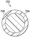
FIG. 7 is a cross-sectional view showing details that may be associated with some exemplary embodiments of the plurality of fibers of FIGS. 5, 6A, and 6B;
FIG. 8 is a schematic perspective view illustrating a second embodiment of a tissue interface for the treatment system of FIG. 1; and
fig. 9 is a flow chart of a second method for manufacturing a tissue interface of the treatment system of fig. 1.
Detailed Description
The following description of exemplary embodiments provides information that enables one of ordinary skill in the art to make and use the subject matter recited in the appended claims, but may omit certain details that are already known in the art. The following detailed description is, therefore, to be regarded as illustrative rather than restrictive.
The exemplary embodiments may also be described herein with reference to the spatial relationships between different elements or the spatial orientations of different elements depicted in the figures. In general, such a relationship or orientation assumes a frame of reference that is consistent with or relative to a patient in a position to be treated. However, those skilled in the art will recognize that this frame of reference is merely a descriptive expedient and is not strictly necessary.
Fig. 1 is a simplified functional block diagram of an exemplary embodiment of a treatment system 100 for providing reduced pressure treatment that includes a tissue interface that includes an embossed mesh film or an embossed manifold-shaped wound filler.
In this context, the term "tissue site" broadly refers to a wound, defect, or other therapeutic target located on or within a tissue, including but not limited to bone tissue, adipose tissue, muscle tissue, neural tissue, skin tissue, vascular tissue, connective tissue, cartilage, tendons, or ligaments. Wounds may include, for example, chronic, acute, traumatic, subacute, and dehiscent wounds, partial cortical burns, ulcers (such as diabetic ulcers, pressure ulcers, or venous insufficiency ulcers), flaps, and grafts. The term "tissue site" may also refer to any area of tissue that is not necessarily wounded or defective, but rather an area in which it may be desirable to increase or facilitate the growth of additional tissue. For example, reduced pressure may be applied to the tissue site to grow additional tissue that may be harvested and transplanted.
The treatment system 100 may include a reduced-pressure supply source and may include or be configured to be coupled to a distribution component or tube (such as a dressing). In general, the distribution component may refer to any supplemental or auxiliary component configured to be fluidly coupled to a reduced pressure supply source in a fluid path between the reduced pressure supply source and a tissue site. The distribution member is preferably removable and may be disposable, reusable or recyclable. For example, the dressing 102 may be fluidly coupled to a reduced-pressure source 104, as shown in fig. 1. In some embodiments, the dressing may include a cover, a tissue interface, or both. The dressing 102 may include, for example, a cover 106 and a tissue interface 108. A regulator or controller, such as controller 110, may also be coupled to reduced pressure source 104.
In some embodiments, the dressing interface may facilitate coupling the reduced-pressure source 104 to the dressing 102. For example, such a dressing interface may be available from texasKCI of San Antonio, Texas Pads or Sensa
 A liner. The
 treatment system 100 may optionally include a fluid container, such as container 112, coupled to the dressing 102 and the reduced pressure source 104.
Additionally, the therapy system 100 may include sensors for measuring operating parameters and providing feedback signals indicative of the operating parameters to the controller 110. For example, as shown in fig. 1, treatment system 100 may include at least one of a pressure sensor 120 or an electrical sensor 122 coupled to controller 110 via electrical conductors 126 and 127, respectively. The pressure sensor 120 may also be coupled or configured to be fluidly coupled to the reduced-pressure source 104 via distribution components (such as fluid conductors 131 and 132). For example, as shown in fig. 1, electrical conductors 126 provide electrical communication between electrical sensor 122 and controller 110. Electrical conductors 127 provide electrical communication between pressure sensor 120 and controller 110. Electrical conductors 128 provide electrical communication between controller 110 and reduced pressure source 104. Electrical conductors 129 provide electrical communication between the electrical sensor 122 and the reduced pressure source 104.
The components may be fluidly coupled to one another so as to provide a path for transferring a fluid (such as at least one of a liquid or a gas) between the components. The components may be fluidly coupled by a fluid conductor (such as a tube). For example, the fluid conductor 130 provides fluid communication between the dressing 102 and the receptacle 112; a fluid conductor 131 provides fluid communication between the reduced-pressure source 104 and the reservoir 112; and fluid conductor 132 provides fluid communication between pressure sensor 120 and reservoir 112. "tube" as used herein broadly includes a tube, pipe, hose, conduit, or other structure having one or more lumens adapted to convey fluid between two ends. Typically, the tube is an elongated cylindrical structure with some flexibility, but the geometry and rigidity may vary. In some embodiments, the components may also be coupled by physical proximity, be integral with a unitary structure, or be formed from the same piece of material. Further, some of the fluid conductors 124 may be molded into or otherwise integrally combined with other components. In some cases, coupling may also include mechanical coupling, thermal coupling, electrical coupling, or chemical coupling (such as chemical bonding). For example, in some embodiments, a tube may mechanically and fluidly couple dressing 102 to container 112.
In general, the components of treatment system 100 may be coupled directly or indirectly. For example, the reduced-pressure source 104 may be coupled directly to the controller 110 and may be coupled indirectly to the dressing 102 through the container 112.
The fluid mechanics of using a reduced pressure source to reduce pressure in another component or location, such as within a sealed treatment environment, can be mathematically complex. However, the rationale for fluid mechanics applicable to reduced pressure treatment is generally well known to those skilled in the art, and the process of reducing pressure may illustratively be described herein as, for example, "delivering," "dispensing," or "generating" reduced pressure.
Generally, exudates and other fluids flow along the fluid path toward lower pressures. Thus, the term "downstream" generally implies a location in the fluid path that is relatively closer to the reduced pressure source or further from the positive pressure source. Conversely, the term "upstream" implies a location relatively further from the reduced pressure source or closer to the positive pressure source. Similarly, it may be convenient to describe certain features in this frame of reference in terms of fluid "inlets" or "outlets". This orientation is generally assumed to describe the different features and components herein. However, in some applications the fluid path may also be reversed, such as by replacing the positive pressure source with a reduced pressure source, and this descriptive convention should not be construed as limiting convention.
"reduced pressure" or "negative pressure" generally refers to a pressure less than the local ambient pressure, which is the ambient pressure in the local environment, such as outside the sealed therapeutic environment provided by dressing 102. In many cases, the local ambient pressure may also be the atmospheric pressure at the location of the tissue site. Alternatively, the pressure may be less than a hydrostatic pressure associated with tissue at the tissue site. Unless otherwise stated, the values of pressure stated herein are gauge pressures. Similarly, reference to an increase in reduced pressure typically refers to a decrease in absolute pressure, while a decrease in reduced pressure typically refers to an increase in absolute pressure. While the amount and nature of the reduced pressure applied to the tissue site may vary depending on the treatment requirements, the pressure is generally a low vacuum, also commonly referred to as a rough vacuum, between-5 mm Hg (-667Pa) and-500 mm Hg (-66.7 kPa). A common treatment range is between-75 mmHg (-9.9kPa) and-300 mm Hg (-39.9 kPa).
The reduced pressure supply source (such as reduced pressure source 104) may be an air reservoir at reduced pressure, or may be a manually or electrically driven device that can reduce the pressure in the sealed volume, such as a vacuum pump, suction pump, wall suction port or micropump that may be used in many healthcare facilities. The reduced pressure supply may be housed within or used in conjunction with other components, such as sensors, processing units, alarm indicators, memory, databases, software, display devices, or user interfaces that further facilitate treatment. For example, in some embodiments, reduced pressure source 104 may be combined with controller 110 and other components into a therapy unit. The reduced pressure supply source may also have one or more supply ports configured to facilitate coupling and decoupling of the reduced pressure supply source to the one or more distribution members.
A sensor, such as pressure sensor 120 or electrical sensor 122, is generally considered in the art to be any device operable to detect or measure a physical phenomenon or characteristic, and generally provides a signal indicative of the detected or measured phenomenon or characteristic. For example, pressure sensor 120 and electrical sensor 122 may be configured to measure one or more operating parameters of therapy system 100. In some embodiments, the pressure sensor 120 may be a transducer configured to measure pressure in the pneumatic circuit and convert the measurement into a signal indicative of the measured pressure. In some embodiments, for example, the pressure sensor 120 may be a piezoresistive strain gauge. In some embodiments, electrical sensor 122 may optionally measure an operating parameter of reduced pressure source 104, such as a voltage or current. Preferably, the signals from pressure sensor 120 and electrical sensor 122 are suitable as input signals to controller 110, but in some embodiments, it may be suitable to make some signal adjustments. For example, the signal may need to be filtered or amplified before being processed by the controller 110. Typically, the signals are electrical signals, but may be represented in other forms, such as optical signals.
The container 112 may represent a container, canister, bag, or other storage component that may be used to manage exudates and other fluids drawn from the tissue site. In many environments, a rigid container may be preferable or desirable for collecting, storing, and disposing of fluids. In other environments, the fluid may be properly disposed of without the need for rigid container storage, and the reusable container can reduce waste and costs associated with reduced pressure therapy.
In some embodiments, the cap 106 can provide a bacterial barrier and avoid physical trauma. The cap 106 may also be constructed of a material that reduces evaporation losses and provides a fluid seal between two components or two environments, such as between a therapeutic environment and a local external environment. The cap 106 may be, for example, an elastomeric film or membrane that may provide a seal sufficient to maintain reduced pressure at the tissue site for a given reduced-pressure source. In some applications, the cover 106 may have a high Moisture Vapor Transmission Rate (MVTR). For example, in some embodiments, the MVTR may be at least 300g/m ^2 every twenty-four hours. In some exemplary embodiments, the cover 106 may be a water vapor permeable but liquid impermeable polymeric drape, such as a polyurethane film. Such drapes typically have a thickness in the range of 25-50 μm (microns). For permeable materials, the permeability generally should be low enough so that the desired reduced pressure can be maintained.
The cover 106 can be attached to an attachment surface, such as an undamaged skin, a pad, or another cover, using an attachment device. The attachment means may take a variety of forms. For example, the attachment means may be a medically acceptable pressure sensitive adhesive that extends around a perimeter, a portion, or all of the sealing member. In some embodiments, for example, some or all of the cover 106 may be coated with an acrylic adhesive and the coating weight is between 25-65 grams per square meter (g.s.m). In some embodiments, a thicker adhesive or combination of adhesives may be applied to improve sealing and reduce leakage. Other exemplary embodiments of the attachment device may include double-sided tape, paste, hydrocolloid, hydrogel, silicone gel, or organogel.
The tissue interface 108 may be configured to contact a tissue site. The tissue interface 108 may be in partial or complete contact with the tissue site. If the tissue site is a wound, for example, the tissue interface 108 may partially or completely fill the wound, or may be placed over the wound. The tissue interface 108 may take many forms and may have a variety of sizes, shapes, or thicknesses depending on a variety of factors, such as the type of treatment being performed or the nature and size of the tissue site. For example, the size and shape of the tissue interface 108 may accommodate the contours of deep and irregularly shaped tissue sites. In addition, any or all surfaces of the tissue interface 108 may have protrusions or uneven, rough, or jagged contours that may cause strain and stress at the tissue site, which may promote granulation growth at the tissue site.
In some embodiments, the tissue interface 108 may be a manifold. In this context, a "manifold" generally includes any substance or structure that provides multiple pathways adapted to collect or distribute fluid under pressure across a tissue site. For example, the manifold may be adapted to receive reduced pressure from the source and distribute the reduced pressure across the tissue site through the plurality of apertures, which may have the effect of collecting fluid from the tissue site and drawing the fluid toward the source. In some embodiments, the fluid path may be reversed or a secondary fluid path may be provided to facilitate delivery of fluid across the tissue site.
In operation, referring at least to fig. 1, the tissue interface 108 may be placed within, over, on, or otherwise proximate to a tissue site. The cap 106 can be placed over the tissue interface 108 and sealed to an attachment surface that can be proximate, surrounding, or adjacent to the tissue site. For example, the cap 106 may be sealed to the intact epidermis surrounding the tissue site. Accordingly, the dressing 102 may provide a sealed treatment environment proximate the tissue site that is substantially isolated from the external environment, and the reduced-pressure source 104 may reduce the pressure in the sealed treatment environment. Reduced pressure applied across the tissue interface 108 on the tissue site in the sealed therapeutic environment may induce macro-and micro-strains in the tissue site and remove exudates and other fluids from the tissue site that may be collected in the container 112.
The tissue interface 108 may include one or more fabrics having various shapes, including, for example, a fabric having a sheet-like shape or a thicker fabric having a more three-dimensional shape. The sheet-like shape may include a shape in which a portion of the shape is thin compared to its length or its width or breadth. The sheet may comprise a mesh or a pad. The mesh may comprise a woven, knitted or braided material having an open texture of uniformly spaced apertures. The mesh may also include a mesh pattern or configuration. The mesh may also include an interwoven structure. The pad may comprise a tangled and sometimes thick bulky material that is compressed in at least some cases. The mat may also comprise a densely felted material.
Three-dimensional fabrics have various geometric shapes, such as circular or rectangular, or various irregular shapes. The fabric may have various characteristics such as non-linting fabric, elastic fabric, hydrophobic fabric, and hydrophilic fabric. Exemplary embodiments of three-dimensional fabrics may include those available from MULLERTM3MESH ofTM. The fabric may serve various functions such as the manifold fabric, the space fabric, the spacer fabric, the filler, or a combination of several functions described above. In some embodiments, the three-dimensional fabric may have a thickness between about 1.0mm (millimeters) and about 50 mm. The tissue interface 108 may comprise one or more layers of the same or different fabrics that may be stacked together, laminated to one another, welded together, or sealed together by various different adhesives.
The three-dimensional fabric may comprise a spacer fabric. The spacer fabric may comprise a knitted fabric comprised of two separate knitted substrates that pass therebetweenThe spacer yarns are joined together or kept separate. The spacer fabric may further comprise a first hydrophilic layer, a second hydrophobic layer and a spacer layer having monofilaments or multifilaments. Exemplary embodiments of spacer fabrics may include those available from BALTEXTMHEATHCOAT ofTMAnd XD SPACERTM。
As noted above, the fabric may comprise an elastic material that may be elastic when compressed or expanded. For example, the fabric may be compressed or stretched in different directions and return to its original shape and size when compression or stretching ceases. In some embodiments, the fabric may be expanded to a fixed shape forming a three-dimensional structure (such as a scaffold). The fabric may be used as a scaffold to promote cell growth. A scaffold is generally a substance or structure used to enhance or promote cell growth or tissue formation, such as a three-dimensional porous structure that provides a template for cell growth. Illustrative examples of scaffold materials include calcium phosphate, collagen, PLA/PGA, coral hydroxyapatite, carbonate, or processed allograft material. In various embodiments, the fabric may be constructed of a bioabsorbable material. When the fabric is constructed of a bioabsorbable material, if a portion of the fabric remains within the tissue site after the tissue interface 108 is removed, the portion of the fabric does not cause infection or irritation at the tissue site. Suitable bioabsorbable materials can include, but are not limited to, polymeric blends of polylactic acid (PLA) and polyglycolic acid (PGA). The polymeric blend may also include, but is not limited to, at least one of polycarbonate, polyfumarate, or caprolactone.
In at least some embodiments, the fabric can be a treated fabric. For example, the fabric may be treated or coated with a hydrophilic material or an elastomeric membrane. The treatment may include coating or impregnating the fabric with a hydrophilic material, or bonding a hydrophilic material to the fabric. In some embodiments, the hydrophilic material or elastic membrane may be applied to the fabric in a particular pattern such that some portions of the fabric are treated while other portions of the fabric are not. The elastic film may include a thermoplastic elastomer (TPE), a thermoplastic vulcanizate (TPV), a Thermoplastic Polyurethane (TPU), or a polyether block amide (PEBAX). The fabric may be treated with a hydrophilic material or an elastomeric membrane to provide at least one of fluid transport, wicking, or absorption properties. For example, a fabric of the tissue interface 108 treated with a hydrophilic material or an elastomeric membrane may allow the tissue interface 108 to wick fluid away from the tissue site while continuing to distribute reduced pressure to the tissue site.
In some embodiments, the fabric may have a textured surface. For example, the fabric may be textured or treated to form a textured surface having a non-uniform, rough, jagged profile or other profile capable of inducing micro-strain and/or stress at the tissue site when reduced pressure is applied to the fabric. When the pressure in the sealed treatment environment is reduced or adjusted such that some movement of the textured surface of the fabric adjacent the tissue site occurs, the textured surface of the fabric may promote granulation growth at the tissue site.
As indicated above, the fabric may comprise a frame or structure in the form of a mesh or mat comprising a plurality of strands or fibers woven or knitted together to form the fabric. Referring more particularly to fig. 2 and 3, the tissue interface 108 includes a fabric 202 formed from a plurality of strands or fibers 206 that are woven together in an orthogonal pattern to form the fabric 202. The fibers 206 may be coupled together using, for example, bonding (such as welding or adhesive). In some embodiments, the fibers 206 may be fused together using chemical or thermal fusion. Each of the fibers 206 may have a cross-sectional shape that includes a circle, polygon, oval, or other geometric shape. In some embodiments, the fibers 206 may have a relatively flat rectangular cross-section to form, for example, a mat. One of ordinary skill in the art will be able to identify the various types of cross-sectional shapes required for the fiber to form the fabric type that may be desired for the tissue interface 108 necessary to treat the tissue site.
The fibers 206 may be formed by providing the fibers from one or more yarns or one or more polymeric materials. For example, the fibers 206 may be formed from a variety of different types of yarns or various types of polymeric materials. The polymeric material may include at least one of a non-foam material or a nonwoven material. One of ordinary skill in the art will be able toThe type of yarn and polymer material that best fits the fabric 202 is identified. Effective examples of polymeric membranes include those available from Delstar Technologies, Inc., Middletown, Delaware Apertured film and
 an engineered composite. In some embodiments, the polymer film may include a thermoplastic elastomer (TPE), a thermoplastic vulcanizate (TPV), a Thermoplastic Polyurethane (TPU), or a polyether block amide (PEBAX).
In various exemplary embodiments, the fabric 202 may be perforated or textured to enhance wound therapy. The fabric 202 may include indentations or recesses on the surface of the fabric 202. The fabric 202 may be perforated to include one or more fenestrations or perforations 204 extending through any of the embodiments of the fabric 202 described above. Perforations 204 may communicate fluid through fabric 202 to enhance wound therapy, including negative pressure wound therapy. The fabric 202 may also include a surface having one or more indentations or recesses thereon that do not extend through the fabric 202. Such indentations or recesses may have various shapes, such as one or more grooves 208 or dimples 210 as shown in more detail in fig. 3.
In some embodiments, the fibers 206 of the fabric 202 forming the tissue interface 108 may be loosely woven to leave voids or gaps between the individual fibers 206. The gaps between the fibers 206 may be uniformly or randomly formed through the fabric 202 to facilitate fluid communication through the tissue interface in a manner similar to the perforations 204 when, for example, reduced pressure is applied to the tissue interface 108. In some embodiments, the gaps may be formed such that they are more concentrated in one area of the tissue interface 108 to enhance the application of reduced pressure, while being less concentrated in other areas of the tissue interface 108. In some embodiments of the fabric 202, the gaps may be formed through the fabric 202 in combination with one or more of the other features described herein. For example, gaps may be formed on the fabric 202 between or along with dimples 210 and/or grooves 208.
In any embodiment of the tissue interface 108, the fabric 202 may be perforated such that one or more fenestrations or perforations 204 extend through the fabric 202. The perforations 204 may be fluidly connected to the fabric 202 to enhance wound therapy, including negative pressure wound therapy. The perforations 204 may be formed by punching through the fabric 202, perforating the fabric 202, cutting holes in the fabric 202, or any of a variety of different methods. The perforations 204 may also be formed by a vacuum forming process. Perforations 204 may be formed in one or more shapes, including, for example, elliptical shapes, including circles, polygons, ovals, or simple slots through the material. The perforations 204 having an elliptical shape may have a diameter between about 300 μm and about 1000 μm. The perforations 204 may be stretched in different directions to change the shape of the perforations 204. Stretching the fabric 202 in one or more directions to form different shapes and sizes facilitates fluid communication through the fabric 202. Perforations 204 may be randomly located throughout fabric 202. In at least some embodiments, the perforations 204 may be positioned such that one or more perforations 204 are more concentrated in one area of the fabric 202, while other perforations 204 are less concentrated in other areas of the fabric 202. In some embodiments of the tissue interface 108, the fabric 202 may include perforations 204 formed through the fabric 202 in combination with one or more of the other features described herein. For example, the perforations 204 may be through holes extending through the fabric 202 from the base of the grooves discussed herein rather than or in addition to the surface of the fabric 202.
In any of the embodiments of the tissue interface 108 described herein, the fabric 202 may additionally or alternatively be textured such that one or more indentations, recesses, protrusions, or roughened portions of various shapes and sizes may be positioned on or within the surface of the fabric 202. The indentations, recesses, protrusions, or asperities may not extend through the fabric 202. The surface of the fabric 202 may include a pattern or arrangement of particles or components of the fabric 202. In another exemplary embodiment, the surface of the weave fabric 202 may include any flexible or rigid protrusions extending from one side of the fabric 202. Such patterns or protrusions may have various shapes, such as pyramids, cylinders, ribs, or other non-symmetrical shapes. The protrusions may be arranged in a regular or irregular pattern, and the pattern itself is formed irregularly and/or asymmetrically on the surface of the fabric 202. The protrusions of the surface may be formed with a coarse or fine grained surface. The surface may be formed by an embossing process that covers the surface of the fabric 202 with a pattern of protrusions that are raised above the surface of the fabric 202.
As shown in at least fig. 3, the tissue interface 108 may include a fabric 202 having one or more recesses or indentations to provide one or more grooves 208. Grooves 208 may be located or formed on the surface of fabric 202. For example, the grooves 208 may direct or direct fluid along the surface of the fabric 202 when reduced pressure is applied through the tissue interface 108. Grooves 208 may be randomly positioned or formed in an irregular pattern on web 202. In various embodiments, the trench 208 may be formed by: embossing the web 202 (e.g., using an embossing roll), pressing a pattern of grooves into the surface of the web 202, vacuum forming the web 202, or by any other method known to those skilled in the art. In some embodiments, portions of the fabric 202 may be reinforced such that grooves 208 may be formed and maintained on the surface of the fabric 202. The grooves 208 may have a variety of different shapes and sizes positioned at locations formed on the surface of the fabric 202. The grooves 208 may have a linear shape, a curved shape, or an angled shape formed on the surface of the fabric 202. The groove 208 may have a cross-sectional shape that includes a semi-circular shape, a general shape, a V-shape, a circle, or any other geometric shape known to those skilled in the art. The trench 208 may have a depth of between about 200 μm and about 1000 μm and a width of between about 200 μm and about 1000 μm. In various embodiments, at least one of the grooves 208 may be positioned or formed on a surface of the fabric 202 to intersect with other features described herein (including at least one of the protrusion 204 or another groove 208). In at least some embodiments, the grooves 208 may be positioned on the surface of the fabric 202 such that some of the grooves 208 are more concentrated in one area of the fabric 202, while other grooves 208 are less concentrated in another area of the fabric 202. In various embodiments, the grooves 208 may be sized, shaped, or positioned on the surface of the fabric 202 such that the grooves 208 cannot fold over themselves or on a separate layer or fabric of the tissue interface 108 and cannot block another groove 208.
As shown in at least fig. 3, the tissue interface 108 may include a fabric 202 having recesses or indentations to provide one or more dimples 210. The dimple 210 may be located or formed on the surface of the tissue interface 108. The dimples 210 can create a greater surface area on the surface of the tissue interface 108 to facilitate absorption of fluid into the pores of the tissue interface 108. The tissue interface 108 may be textured to form one or more dimples 210 in a variety of ways: pressing the pattern of dimples 210 into the surface of the tissue interface 108, vacuum forming the pattern of dimples 210 into the surface of the tissue interface 108, or any other method known to those skilled in the art. At least one of the dimples 210 can have a diameter of between about 50 μm and about 2000 μm. The dimple 210 can have a hollow shape, including the shape of a cone, ellipsoid, hemisphere, or polyhedron. The dimples 210 can also have a depth of between about 200 μm and about 1000 μm. The dimple 210 can have a variety of different shapes and sizes positioned at locations formed on the surface of the tissue interface 108. The dimples 210 can be randomly positioned or formed on the tissue interface 108 in an irregular pattern. In at least some embodiments, the dimples 210 can be positioned such that some of the dimples 155 are more concentrated in at least one region of the tissue interface 108, while other dimples 155 are less concentrated in another region of the tissue interface 108. In some embodiments, portions of the fabric 202 may be reinforced such that dimples 210 are maintained on the surface of the fabric 202. In various embodiments, the dimple 210 can be sized, shaped, or positioned on the surface of the tissue interface 108 such that the dimple 210 cannot fold over on itself or on a separate layer of the tissue interface 108 and cannot block the groove 208 or another dimple 210.
As discussed herein, the fabric 202 may include at least one of a mesh, a pad, or a spacer fabric. In some embodiments, the fabric 202 may be a web formed from one or more fibers 206 of a plurality of fibers 206 woven together to form the fabric 202. In some embodiments, the fabric 202 may be a mat formed from one or more fibers 206 of a plurality of fibers 206 pressed together to form the fabric 202. In some embodiments, the fabric 202 may be a spacer fabric formed from one or more fibers 206 of the plurality of fibers 206 having a thicker three-dimensional shape to form or maintain a space between one or more other elements, such as the cap 106 and tissue site discussed with respect to fig. 1.
Fig. 4 is a flow chart of a method 400 for manufacturing a fabric of a tissue interface of the treatment system 100 of fig. 1. At step 405, a fabric of a tissue interface may be formed. The fabric may be the same as or similar to at least the fabric 202 of fig. 2 and 3. The tissue interface may be the same as or similar to at least the tissue interface 108 of fig. 1. The fabric 202 may include a plurality of fibers, such as the fibers 206 shown in fig. 2 and 3. The fibers 206 may be extracted from the polymeric material, for example, by using an extrusion process. The polymeric material may also include at least one of a polymeric film or a nonwoven material. The fibers 206 may be joined, braided, woven, bonded, or fused together as discussed herein. At step 410, the fabric 202 of the tissue interface 108 may be perforated or windowed to form one or more perforations 204. In at least some embodiments, the fabric 202 can be stretched to change the shape of the perforations 204. At step 415, the fabric 202 may be formed to include one or more grooves 208. At step 420, a hydrophilic material may be applied to the fabric 202. The hydrophilic material may include at least one of a coating or a hydrophilic binder. At step 425, the fabric 202 may be fused with one or more fused fibers. At step 430, the fabric 202 may be coated with an expanded polymer. At step 435, an absorbent layer may be disposed on the fabric 202.
Turning to at least fig. 5, the tissue interface 508 may have a fabric 502 with one or more layers 504. The tissue interface 508 may be the same as or similar to the tissue interface 108 shown in fig. 1, 2, and 3. The fabric 502 may be the same as or similar to the fabric 202 of fig. 2 and 3. Each of the layers 504 of the fabric 502 may include a plurality of fibers 506. In some embodiments, the plurality of fibers 506 may be the same as or similar to the plurality of fibers 206 of fig. 2 and 3. Each of the fibers 506 may comprise the same material or a variety of different materials. Additionally, the fibers 506 of the first layer may be of the same material as the fibers 506 of the second layer, or the fibers 506 of the first layer may be of a different material than the fibers 506 of the second layer. As shown in fig. 5, the one or more layers 504 can include at least a top layer 510, a middle layer 512 (such as a surface middle layer), and a bottom layer 514. The top layer 510 and the bottom layer 514 may include fibers 506 that allow the fabric 502 to flex. The middle layer 512 may include fibers 506 that are more elastic than the fibers 506 of the top layer 510 and the bottom layer 514. In some embodiments, the middle layer 512 may have a greater concentration of fibers 506 than the top layer 510 and the bottom layer 514.
Fig. 6A is a perspective view of a first embodiment of at least some of the plurality of fibers 506 of the tissue interface 508 of fig. 5 in contact with each other. As shown in fig. 6A, each of the fibers 506 may be in physical contact with each other or disposed proximate to each other at fiber intersections 602 and 604. Fig. 6B is a perspective view of a second embodiment of at least some of the plurality of fibers 506 of the tissue interface 508 of fig. 5 coupled to one another. As shown in fig. 6B, each of the fibers 506 may be coupled to one another at fiber intersections 602 and 604. It should be understood that the term "coupled" may include bonded, fastened, glued, welded, or otherwise securely contacted.
After knitting or weaving the fibers 506 to form the fabric 502, the fibers 506 may be coupled to one another, arranged in direct physical contact with one another, or arranged in close proximity to one another at fiber intersections. As shown in fig. 6A, the fibers 506 may cross over each other at fiber intersections 602 and 604. Although the fibers 506 shown in fig. 6A may be in direct physical contact with each other or may be in close contact with each other at the fiber intersections 602 and 604, the fibers 506 may be able to move freely because they are not coupled to each other. As shown in fig. 6B, the fibers 506 may be coupled to each other at fiber intersections 602 and 604. Thus, in the exemplary embodiment of fig. 6B, the fiber 506 may not be free to move at the fiber intersections 602 and 604. The fibers 506 may be coupled to one another at fiber intersections 602 and 604, for example, to stop or reduce linting when the fabric 502 is cut or removed from a wound. The fibers 506 may be coupled to one another in a variety of ways, including at least one of: using adhesives, heat, melting, fusing, twisting, binding, compressing, or other methods known to those of ordinary skill in the art. In some embodiments, after the fibers 506 are coupled to one another, a coating (such as a solvent coating, a water-based coating, or a foam-based coating) may be applied over the fibers 206 that, upon drying, will deposit a thin, high-strength elastic polymer film over the fibers 506.
In some embodiments, one or more voids or interstices 607 may be formed between the fibers 506 when the fibers 506 are coupled to one another to communicate fluid through the fabric 502. In various embodiments, joining the fibers 506 at the fiber intersections 602 and 604 may create defective joints between the fibers 506. A defective attachment refers to portions of a fiber 506 being attached to another fiber 506 while other portions of the same fiber 506 are not attached to the same fiber 506 or another fiber 506. Thus, a defective coupling may provide a portion of a fiber 506 that is free or unconnected to another fiber 506 to form a gap 607 between the fibers 506.
In at least some embodiments, the fiber intersections 602 and 604 can be randomly located or can occur at different locations along a particular fiber 506. Different locations of the fiber intersections 602 and 604 may form gaps 607 of different sizes through the fabric 502. For example, a larger gap 607 through the fabric 502 is formed compared to fibers 506 having two fiber intersections with other fibers 506 and a first distance from each other than fibers 506 having two fiber intersections with other fibers 506 and a second distance from each other that is shorter than the first distance. It should be understood that although fig. 6A and 6B illustrate fibers 206 having two fiber intersections, fibers 506 may have one or more intersections.
It should also be appreciated that the concentration of fibers or fiber density in the fabric 502 may affect the size of the gaps 607 and the number of gaps 607 that pass through the fabric 502. For example, a first portion of the fabric 502 (such as a first layer of the fabric 502) may have a greater concentration of fibers 506 than a second portion of the fabric 502 (such as a second layer of the fabric 502). Thus, a first portion of the fabric 502 may have more fiber intersections on a particular fiber 506 than fibers 506 of a second portion of the fabric 502. The more fiber intersections that are present on a particular fiber 506, the shorter the distance that can be present between the fiber intersections on that particular fiber 506. Thus, a first portion of web 502 may have gaps 607 that have a smaller cross-sectional area than the gaps 607 of a second portion of web 502. Further, as the number of fiber intersections on a particular fiber 506 increases, the number of gaps 607 may also increase over a particular portion of the fabric 502. Thus, for example, a first portion of the fabric 502 may have more gaps 607 than a second portion of the fabric 502 because the fibers 506 of the first portion may have more fiber intersections than the fibers 506 of the second portion.
In some embodiments, the fibers 506 may be coupled to each other using heat. The heat may create a temperature gradient through the fabric 502 that may also affect the size of the gaps 607 and the number of gaps 607 that pass through the fabric 502. For example, after forming the fabric 502 and the fabric 502 is subjected to a heating process that causes the fibers to reduce shrinkage, fibers 506 in the layers that are located closer to the surface of the fabric 502 may be subject to more melting than fibers 506 that are located further from the surface of the fabric 502 or closer to the center thereof. This may be because of the reliance on heat sources external to the fabric 502 to transfer heat to the fabric 502 and to create a temperature gradient across the fabric. Because fibers 506 closer to the surface of fabric 502 may be subject to more melting than fibers located farther from the surface of fabric 502 or closer to the center of fabric 502, more fibers closer to the surface of fabric 502 may be joined at more fiber locations. The temperature gradient across the fabric 502 can form more gaps 607 and gaps 607 having a smaller cross-sectional area at locations of the fabric 502 closer to the surface of the fabric 502 relative to locations of the fabric 502 further away from the surface of the fabric 502 or closer to the center of the fabric 502. Thus, the greater the temperature gradient across fabric 502, the greater the number of gaps 607 and the smaller the cross-sectional area of each of gaps 607 in the area closer to the surface of fabric 502 or closer to the heat source relative to the number of gaps 607 and the size of gaps 607 in the area closer to the center of fabric 502 or further from the heat source.
In various embodiments, one or more of the plurality of fibers 506 in fig. 5, 6A, and 6B may be monocomponent fibers. The monocomponent fibers may be fibers comprising only one material or yarn. In some embodiments, one or more of the plurality of fibers 506 in fig. 5, 6A, and 6B may be bi-monocomponent fibers. Bicomponent fibers may include fibers having two different materials or yarns. Fig. 7 is a cross-sectional view illustrating details that may be associated with some exemplary embodiments of the fiber 506 of fig. 5, 6A, and 6B. Specifically, fig. 7 illustrates an exemplary embodiment of a bicomponent fiber 702. As shown in fig. 7, the bicomponent fiber 702 may include an outer or outer sheath layer 704 and an inner or inner core 706. The outer jacket layer 704 may be made of a first material and the inner core 706 may be made of a second, different material. It should be understood that the fibers 506 of the tissue interface 508 may be entirely bicomponent fibers or a combination of bicomponent fibers and monocomponent fibers.
In some embodiments, the bicomponent fibers 702 may include a first material and a second material, wherein the first material has a lower melting point than the second material. For example, the bicomponent fiber 702 may include an outer sheath layer 704 made of a first material having a lower melting point than a second material forming an inner core 706. Thus, after forming the fabric 502 including the bicomponent fibers 702, the fabric 502 may be subjected to a heating process that reduces shrinkage of the fibers. The heating process may be to a temperature that also melts at least a portion of the outer sheath layer 704 of the bicomponent fibers 702 without melting the inner core 706 of each of the bicomponent fibers 702. The first material of the outer jacket layer 704 has a lower melting point relative to the higher melting point of the second material of the inner core 706, which may cause the outer jacket layer 704 to melt in a temperature range that does not melt the inner core 706. One of ordinary skill in the art should be able to identify a temperature range in which the first material of the outer jacket layer 704 can be melted without melting the second material of the inner core 706. Because the outer jacket layer 704 melts, the bicomponent fibers 702 may join other fibers, including monocomponent fibers or other bicomponent fibers 702, at fiber intersections where the fibers are in close or direct physical contact.
Fig. 8 is a schematic perspective view illustrating a second embodiment of a tissue interface for the treatment system 100 of fig. 1. The tissue interface shown in fig. 8 may be the same as or similar to the tissue interface 108 shown in fig. 1 or the tissue interface 508 shown in fig. 5. For example, the tissue interface 808 may include one or more features of the tissue interface 108 of fig. 1. In the exemplary embodiment of fig. 8, the tissue interface 808 may include a fabric 802. The fabric 802 may be the same as or similar to the fabric 202 of fig. 2 and 3 or the fabric 502 of fig. 5. In some embodiments, after forming the fabric 802, a strong elastic polymer coating, such as a polyurethane dispersion (PUD) coating, may be applied to the fabric 802. Useful examples of PUD coatings include those available from BAYERTMThe PUD coating of (1). The fabric 802 may also be pre-cut in size, where the edges are fused and sealed to prevent or reduce linting. In some embodiments, the pre-cut fabric may be cut into individual sizes. In some embodiments, the edges of the pre-cut fabric may be stitched, for example using an over-lock stitch technique that encapsulates any free fibers with the fabric 802. In some embodiments, the edges of the pre-cut web may be fused using a hot cutting blade, ultrasonic fusion, or radio frequency fusion. As shown in the exemplary embodiment of fig. 8, the fabric 802 may be cut into one or more fabric sheets, such as a first fabric sheet 804, a second fabric sheet 806, and a third fabric sheet 807. Each of the one or more fabric sheets may be connected to each other using fibers 810 and 812. Fibers 810 and 812 may be cut by a user to place a single piece of fabric into a wound or tissue site.
Fig. 9 is a flow diagram of a second method 900 for manufacturing a tissue interface of the treatment system of fig. 1. At step 905, a fabric of a tissue interface may be formed. The fabric may be the same as or similar to the fabric 202 of fig. 2 and 3, the fabric 502 of fig. 5, or the fabric 802 of fig. 8. The tissue interface may be the same as or similar to the tissue interface 108 of fig. 1, the tissue interface 508 of fig. 5, or the tissue interface 808 of fig. 8. The fabric may include a plurality of fibers, such as the fibers 206 of fig. 2 and 3, the fibers 506 of fig. 5, or the bicomponent fibers 702 of fig. 7. At step 910, each of the fibers may be on one or more fibersAre coupled to each other at the intersection points. At step 915, the fabric may be coated with a material, such as a solvent or foam based material, which when dried will deposit a thin high strength elastic polymer film on the fibers. The effective gap sizes of the fabrics may each be different due to, for example, the concepts discussed herein. Thus, the fabric may have both large and small gap sizes on the surfaces of the tissue interface 808 (such as on the top and bottom layers). Fabrics with large gaps on the surface can be used at wound contact sites where granulation is desired. Fabrics with small gaps can be used where little or no granulation is required. The fabric may also be structured to provide a range of apposition forces in different directions depending on the orientation used when placing the fabric in the wound or tissue site. The strength of the fabric as discussed herein can be significantly higher than GRANUFOAMTMAnd gauze, while at least reducing the risk of leaving debris in the wound due to increased strength of the fabric after removal of the fabric. In some embodiments, the fabrics discussed herein may include radiopaque materials that allow for X-ray localization. In some embodiments, the fibers discussed herein may include an antimicrobial agent, such as silver.
The systems, devices, and methods described herein may provide significant advantages. For example, a tissue interface (such as a wound filler) may reduce trauma and facilitate convenient removal when treating both deep and shallow wounds. The tissue interface promotes granulation without the disadvantage of tissue ingrowth that leads to pain or discomfort after removal.
While shown in some illustrative embodiments, one of ordinary skill in the art will recognize that the systems, devices, and methods described herein are susceptible to various changes and modifications. Moreover, the use of terms such as "or" does not require mutual exclusivity in describing the various alternatives unless the context clearly requires otherwise, and the indefinite article "a" or "an" does not limit the subject matter to a single instance unless the context clearly requires otherwise. Components can also be combined or eliminated in various configurations for purposes of sale, manufacture, assembly, or use. For example, in some configurations, the dressing 102, the container 112, or both may be eliminated or manufactured or sold separately from the other components. In other exemplary configurations, the controller 110 may also be manufactured, configured, assembled, or sold independently of other components.
The accompanying claims set forth novel and inventive aspects of the above-described subject matter, but the claims may also encompass additional subject matter that is not explicitly recited. For example, certain features, elements, or aspects may be omitted from the claims if not necessary to distinguish the novel and inventive features from features known to those of ordinary skill in the art. The features, elements, and aspects described herein may also be combined or substituted with alternative features serving the same, equivalent, or similar purpose, without departing from the scope of the invention, which is defined by the claims.
Claims (111)
1. A method of manufacturing a tissue interface for a reduced-pressure tissue treatment system, the method comprising:
forming a fabric comprising a plurality of fibers, wherein each of the plurality of fibers comprises a polymeric material;
coupling the plurality of fibers of the fabric together; and
applying a hydrophilic material to the plurality of fibers.
2. The method of claim 1, wherein the plurality of fibers are one of bicomponent fibers or monocomponent fibers.
3. The method of claim 1, further comprising applying a coating to the plurality of fibers, the coating comprising at least one of a solvent-based coating, a water-based coating, or a solvent-free liquid coating.
4. The method of claim 3, wherein the coating is an elastomeric polymer coating.
5. The method of claim 3, wherein the elastomeric polymer coating comprises a polyurethane dispersion (PUD) coating.
6. The method of claim 1, wherein each of the plurality of fibers comprises an outer jacket material formed on an inner material, and wherein the outer jacket material has a lower melting point than the inner material.
7. The method of claim 6, wherein coupling the plurality of fibers comprises melting an outer jacket material of at least one of the plurality of fibers without melting an inner material of each of the plurality of fibers.
8. The method of claim 1, wherein forming the fabric comprises forming a fabric having a top layer, a surface intermediate layer, and a bottom layer.
9. The method of claim 8, wherein at least one of the top layer, the superficial intermediate layer, or the bottom layer comprises at least one fiber that is different from one or more remaining fibers of the plurality of fibers of the fabric.
10. The method of claim 1, wherein at least one of the plurality of fibers comprises at least one of a woven material, a non-woven material, or a knitted material.
11. The method of claim 10, wherein the woven, nonwoven, or knitted material has a thickness between about 1 millimeter (mm) and about 30 mm.
12. The method of claim 1, wherein coupling the plurality of fibers comprises heating the plurality of fibers.
13. The method of claim 1, wherein the fabric has a thickness between about 1mm and about 2 mm.
14. The method of claim 1, wherein the fabric comprises one or more perforations.
15. The method of claim 14, wherein each of the one or more perforations is between about 3mm and about 2mm in diameter or width.
16. The method of claim 1, wherein a first set of fibers of the plurality of fibers form at least one of a top layer of the fabric or a bottom layer of the fabric.
17. The method of claim 16, wherein the first set of fibers has a first density, and wherein the first set of fibers is configured to allow flexibility of the fabric.
18. The method of claim 17, wherein a second group of the plurality of fibers forms an interfacial layer of the fabric, and wherein the second group of fibers has a second density that is greater than the first density.
19. The method of claim 1, further comprising configuring the fabric to be positioned at or within a wound.
20. The method of claim 19, wherein deploying the fabric comprises trimming the fabric.
21. The method of claim 19, further comprising fusing one or more edges of the fabric after configuring the fabric to be positioned at the wound or wound using at least one of a thermal cutting blade, an ultrasonic technique, or a radio frequency technique.
22. The method of claim 1, wherein the fabric is configured to retain free fibers.
23. The method of claim 22, wherein the edges of the fabric are stitched over to retain the free fibers.
24. The method of claim 23, wherein stitching is used to overlook the edges of the fabric.
25. A system for providing reduced pressure onto a tissue site, the system comprising:
a cap configured to form a seal over the tissue site;
a reduced-pressure source configured to provide reduced pressure through the cap at the tissue site; and
a tissue interface configured to be disposed beneath the cap at the tissue site and comprising a fabric having a plurality of fibers coupled together.
26. The system of claim 25, wherein the plurality of fibers are one of bicomponent fibers or monocomponent fibers.
27. The system of claim 25, wherein each of the plurality of fibers is coated with a coating comprising at least one of a solvent-based coating or a water-based coating.
28. The system of claim 27, wherein the coating is an elastomeric polymer.
29. The system of claim 28, wherein the elastomeric polymer comprises a polyurethane dispersion (PUD) coating.
30. The system of claim 29, wherein each of the plurality of fibers comprises an outer sheath material formed on an inner material, and wherein the outer sheath material has a lower melting point than the inner material.
31. The system of claim 30, wherein the plurality of fibers are fused together by melting an outer jacket material of at least one of the plurality of fibers without melting an inner material of each of the plurality of fibers.
32. The system of claim 25, wherein the fabric comprises a top layer, a surface intermediate layer, and a bottom layer.
33. The system of claim 32, wherein at least one of the top layer, the superficial intermediate layer, or the bottom layer comprises at least one fiber that is a different material than one or more remaining fibers of the plurality of fibers of the fabric.
34. The system of claim 25, wherein at least one of the plurality of fibers comprises at least one of a woven material, a non-woven material, or a knitted material.
35. The system of claim 34, wherein a thickness of at least one of the woven material, the nonwoven material, or the knitted material is between about 1 millimeter (mm) and about 30 mm.
36. The system of claim 25, wherein the plurality of fibers are coupled together by heating the plurality of fibers.
37. The system of claim 25, wherein the fabric has a thickness between about 1mm and about 2 mm.
38. The system of claim 25, wherein the fabric comprises one or more perforations.
39. The system of claim 38, wherein each of the one or more perforations is between about 3mm and about 2mm in diameter or width.
40. The system of claim 25, wherein a first set of fibers of the plurality of fibers form at least one of a top layer of the fabric or a bottom layer of the fabric.
41. The system of claim 40, wherein the first set of fibers has a first density, and wherein the first set of fibers is configured to allow flexibility of the fabric.
42. The system of claim 41, wherein a second group of the plurality of fibers forms an interfacial layer of the fabric, and wherein the second group of fibers has a second density that is greater than the first density.
43. The system of claim 25, wherein the fabric is configured to be positioned at or within a wound.
44. The system of claim 43, wherein the fabric is configured to be positioned at or within a wound by trimming the fabric.
45. The system of claim 25, wherein one or more edges of the fabric are fused together using at least one of a cutting blade, ultrasonic technology, or radio frequency technology.
46. The system of claim 25, wherein the fabric is configured to retain free fibers.
47. The system of claim 46, wherein edges of the fabric are stitched over to retain the free fibers.
48. The system of claim 47, wherein stitching is used to overlook the edges of the fabric.
49. A method of manufacturing a tissue interface for a reduced-pressure tissue treatment system, the method comprising:
forming a mesh comprising a plurality of strands braided together, wherein each of the plurality of strands comprises a polymeric film;
perforating the web to form a perforated web having one or more perforations; and
the perforated web is textured to form a textured perforated web having at least one textured surface.
50. The method of claim 49, wherein the polymer film comprises a nonwoven material.
51. The method of claim 49, wherein texturing the perforated web to form the textured perforated web having at least one textured surface comprises at least one of embossing the perforated web or vacuum forming the perforated web.
52. The method of claim 49, further comprising stretching the perforated web to change the shape of the one or more perforations after perforating the web.
53. The method of claim 49, wherein the shape of the one or more perforations comprises at least one of a circle, a polygon, or an oval.
54. The method of claim 49, wherein the one or more perforations are between about 3mm and about 2 mm.
55. The method of claim 49, wherein the cross-sectional shape of each of the plurality of strands comprises at least one of a circle, a polygon, or an oval.
56. The method of claim 49, further comprising applying a hydrophilic treatment to the web.
57. The method of claim 56, wherein the hydrophilic treatment comprises at least one of a coating or a hydrophilic binder.
58. The method of claim 49, wherein the mesh comprises one or more pores, each pore having a diameter or width between about 300 μm (micrometers) and about 2000 μm.
59. The method of claim 49, wherein the plurality of strands are braided together by bonding at least one of the plurality of strands to at least one other of the plurality of strands using at least one of welding or glue.
60. The method of claim 49, wherein the textured surface comprises at least one of dimples or grooves.
61. The method of claim 60, wherein the dimples are between about 50 μm and about 2000 μm in diameter.
62. The method of claim 60, wherein the dimple shape comprises at least one of a cone, an ellipse, a spherical cap, or a polyhedron.
63. The method of claim 60 wherein the depth of the trench is between about 50 μm and about 1000 μm.
64. The method of claim 60 wherein the width of the trench is between about 50 μm and about 1000 μm.
65. The method of claim 49, further comprising fusing the web with one or more fibers.
66. The method of claim 49, further comprising coating the mesh with an expanded polymer.
67. The method of claim 49, further comprising disposing an absorbent layer on the web.
68. A system for providing reduced pressure onto a tissue site, the system comprising:
a cap configured to form a seal over the tissue site;
a reduced-pressure source configured to provide reduced pressure through the cap at the tissue site; and
a tissue interface configured to be disposed beneath the cap at the tissue site and comprising a textured pad having a plurality of strands of entangled polymeric film and at least one textured surface.
69. The system of claim 68, wherein the polymer film comprises a nonwoven material.
70. The system of claim 68, wherein the pad is textured using at least one of vacuum forming or embossing.
71. The system of claim 70, wherein the pad is perforated to form one or more perforations.
72. The system of claim 71, wherein the shape of the one or more perforations is formed by stretching the perforated pad after forming the one or more perforations.
73. The system of claim 71, wherein the shape of the one or more perforations comprises at least one of a circle, a polygon, an oval, a slot, or a slit.
74. The system of claim 71, wherein the one or more perforations are between about 3mm and about 2mm in diameter or width.
75. A system as in claim 68, wherein the plurality of strands are extruded from one or more polymer films.
76. The system of claim 75, wherein at least one of the plurality of strands comprises a polymer film that is different from the polymer film of at least one other of the plurality of strands.
77. The system of claim 75, wherein the cross-sectional shape of each of the plurality of strands comprises at least one of a circle, a polygon, an oval, a slot, or a slit.
78. The system of claim 75, wherein the plurality of strands are bonded by at least one of welding or glue.
79. The system of claim 68, wherein the tissue interface comprises a hydrophilic treatment comprising at least one of a coating or a hydrophilic adhesive.
80. The system of claim 68, wherein the pad comprises one or more pores, each pore having a diameter or width between about 300 μm (micrometers) and about 2000 μm.
81. The system of claim 68, wherein the textured surface comprises at least one of dimples or grooves.
82. The system of claim 81, wherein the dimple has a diameter between about 50 μm and about 2000 μm.
83. The system of claim 81, wherein the dimple shape comprises at least one of a cone, an ellipse, a spherical cap, or a polyhedron.
84. The system of claim 81, wherein the depth of the trench is between about 50 μm and about 1000 μm.
85. The system of claim 81, wherein the trench has a width of between about 50 μm and about 1000 μm.
86. A system as in claim 68, wherein each of the plurality of strands is fused with one or more fused fibers.
87. The system of claim 68, wherein the pad is coated with an expanded polymer.
88. The system of claim 68, wherein the tissue interface comprises an absorbent layer disposed on the pad.
89. A tissue interface configured to be disposed at a tissue site, the tissue interface comprising:
a textured pad comprising:
a plurality of strands of entangled polymer film, and
at least one of a dimple or a trench; and is
Wherein the organization interface is configured to:
is disposed below the cap at the tissue site, and
a reduced pressure is received from a reduced pressure source.
90. The tissue interface of claim 89, wherein the polymer film comprises a nonwoven material.
91. The tissue interface of claim 89, wherein the pad is textured using at least one of vacuum forming or embossing.
92. The tissue interface of claim 89, wherein the pad is perforated to form one or more perforations.
93. The tissue interface of claim 92, wherein the shape of the one or more perforations is formed by stretching the textured pad.
94. The tissue interface of claim 92, wherein the shape of the one or more perforations comprises at least one of a circle, a polygon, an oval, a slot, or a slit.
95. The tissue interface of claim 92, wherein the one or more perforations are between about 3mm and about 2mm in diameter or width.
96. The tissue interface of claim 89, wherein the plurality of strands are extruded from one or more polymer films.
97. The tissue interface of claim 96, wherein at least one of the plurality of strands comprises a polymer film that is different from a polymer film of at least one other of the plurality of strands.
98. The tissue interface of claim 96, wherein the cross-sectional shape of each of the plurality of strands comprises at least one of a circle, a polygon, an oval, a slot, or a slit.
99. The tissue interface of claim 96, wherein the plurality of strands are bonded by at least one of welding or glue.
100. The tissue interface of claim 90, wherein the tissue interface comprises a hydrophilic treatment comprising at least one of a coating or a hydrophilic adhesive.
101. The tissue interface of claim 100, wherein the pad comprises one or more pores, each pore having a diameter or width between about 300 μ ι η (microns) and about 2000 μ ι η.
102. The tissue interface of claim 100, wherein the textured pad comprises one or more textured surfaces, wherein at least one textured surface comprises at least one of dimples or grooves.
103. The tissue interface of claim 102, wherein the dimple has a diameter between about 50 μ ι η and about 2000 μ ι η.
104. The tissue interface of claim 102, wherein the dimple shape comprises at least one of a cone, an ellipse, a spherical cap, or a polyhedron.
105. The tissue interface of claim 102, wherein the depth of the grooves is between about 50 μ ι η and about 1000 μ ι η.
106. The tissue interface of claim 102, wherein the width of the groove is between about 50 μ ι η and about 1000 μ ι η.
107. The tissue interface of claim 119, wherein each of the plurality of strands is fused to one or more fused fibers.
108. The tissue interface of claim 89, wherein the textured pad is coated with an expanded polymer.
109. The tissue interface of claim 89, wherein the tissue interface comprises an absorbent layer disposed on the textured pad.
110. A tissue interface configured to be disposed at a tissue site, the tissue interface comprising:
a spacer fabric having a top layer, a middle layer, and a bottom layer, wherein each of the top layer, the middle layer, and the bottom layer comprises a plurality of fibers, wherein the plurality of fibers are coupled together by melting an outer sheath of the plurality of fibers without melting an inner material of each of the plurality of fibers, wherein the outer sheath is formed over the inner material of each of the plurality of fibers, wherein the outer sheath has a melting point temperature that is lower than a melting point temperature of the inner material, wherein each of the plurality of fibers is coated with a material comprising at least one of a solvent-based material, a water-based material, or a solvent-free liquid material, wherein the material is an elastic polymer, and wherein the elastic polymer comprises a polyurethane dispersion (PUD) material.
111. A tissue interface configured to be disposed at a tissue site, the tissue interface comprising:
a textured perforated pad, the textured perforated pad comprising:
a plurality of strands of entangled polymeric film, wherein at least one strand of the plurality of strands comprises a polymeric film comprising a material that is different from the material of the polymeric film of at least one other strand of the plurality of strands,
at least one of a dimple or a groove formed on a surface of the pad, an
One or more perforations formed by perforating the pad, wherein the shape of the one or more perforations comprises at least one of a circle, a polygon, or an oval, and wherein the diameter or width of the one or more perforations is between about 3mm and about 2 mm; and is
Wherein the organization interface is configured to:
is disposed below the cap at the tissue site, and
a reduced pressure is received from a reduced pressure source.
Applications Claiming Priority (3)
| Application Number | Priority Date | Filing Date | Title |
|---|---|---|---|
| US201762518283P | 2017-06-12 | 2017-06-12 | |
| US62/518,283 | 2017-06-12 | ||
| PCT/US2018/037086 WO2018231815A2 (en) | 2017-06-12 | 2018-06-12 | Fabric wound filler |
Publications (1)
| Publication Number | Publication Date |
|---|---|
| CN111031976A true CN111031976A (en) | 2020-04-17 |
Family
ID=62779145
Family Applications (1)
| Application Number | Title | Priority Date | Filing Date |
|---|---|---|---|
| CN201880051241.5A Pending CN111031976A (en) | 2017-06-12 | 2018-06-12 | Fabric wound filler |
Country Status (5)
| Country | Link |
|---|---|
| US (1) | US20200085628A1 (en) |
| EP (2) | EP4233814A3 (en) |
| JP (1) | JP2020523116A (en) |
| CN (1) | CN111031976A (en) |
| WO (1) | WO2018231815A2 (en) |
Cited By (2)
| Publication number | Priority date | Publication date | Assignee | Title |
|---|---|---|---|---|
| CN113180753A (en) * | 2021-04-29 | 2021-07-30 | 董蔚 | Bead blanket type progressive repairing sheet for perforation of compartment space |
| CN114053034A (en) * | 2021-11-19 | 2022-02-18 | 青岛大学 | Expansion pressurization band-aid/application and preparation method |
Families Citing this family (2)
| Publication number | Priority date | Publication date | Assignee | Title |
|---|---|---|---|---|
| WO2020263895A1 (en) * | 2019-06-25 | 2020-12-30 | Kci Licensing, Inc. | System for treating a tissue site on an appendage using a flowable tissue dressing material |
| TWI740755B (en) * | 2020-12-24 | 2021-09-21 | 南緯實業股份有限公司 | Dressing |
Citations (12)
| Publication number | Priority date | Publication date | Assignee | Title |
|---|---|---|---|---|
| US20020065494A1 (en) * | 2000-11-29 | 2002-05-30 | Lockwood Jeffrey S. | Vacuum therapy and cleansing dressing for wounds |
| US20020161346A1 (en) * | 2000-11-29 | 2002-10-31 | Lockwood Jeffrey S. | Vacuum therapy and cleansing dressing for wounds |
| WO2006005939A1 (en) * | 2004-07-09 | 2006-01-19 | Ethicon, Inc. | Vacuum wound dressings |
| CN101888821A (en) * | 2007-12-06 | 2010-11-17 | 史密夫及内修公开有限公司 | Dressing |
| CN102209813A (en) * | 2008-09-11 | 2011-10-05 | 阿尔巴尼国际公司 | Permeable belt for the manufacture of tissue, towel and nonwovens |
| CN102697602A (en) * | 2011-02-28 | 2012-10-03 | 强生消费者公司 | Adhesive bandage |
| CN103025941A (en) * | 2010-07-07 | 2013-04-03 | 3M创新有限公司 | Patterned air-laid nonwoven fibrous webs and methods of making and using same |
| CN103655046A (en) * | 2013-12-03 | 2014-03-26 | 佛山市优特医疗科技有限公司 | Wound dressing with three-layer structure and preparation method of wound dressing |
| US20140336557A1 (en) * | 2013-05-10 | 2014-11-13 | Biovation Ii, Llc | Biopolymer multi-layer multi-functional medical dressing and method of making same |
| US20150282991A1 (en) * | 2012-10-29 | 2015-10-08 | Foshan United Medical Technologies, Ltd. | High hygroscopic wound dressing and preparation method and use thereof |
| CN105188780A (en) * | 2013-03-15 | 2015-12-23 | 史密夫及内修公开有限公司 | Wound dressing sealant and use thereof |
| US20160051720A1 (en) * | 2013-05-17 | 2016-02-25 | Shakthi Knitting Limited | Microbicidal composite material |
Family Cites Families (14)
| Publication number | Priority date | Publication date | Assignee | Title |
|---|---|---|---|---|
| CA2674997C (en) * | 2007-02-09 | 2012-08-14 | Kci Licensing, Inc. | A breathable interface system for topical reduced pressure |
| EP2157948B1 (en) * | 2007-05-24 | 2017-02-15 | Applied Tissue Technologies Llc | Wound treatment device employing negative pressure |
| US20130096518A1 (en) * | 2007-12-06 | 2013-04-18 | Smith & Nephew Plc | Wound filling apparatuses and methods |
| DK2309961T3 (en) * | 2008-08-08 | 2018-03-12 | Smith & Nephew Inc | Wound dressing of continuous fibers |
| US20100191196A1 (en) * | 2009-01-26 | 2010-07-29 | Heagle David G | Fibrous Wound Filler Material for Negative Pressure Wound Therapy |
| US8721606B2 (en) * | 2010-03-11 | 2014-05-13 | Kci Licensing, Inc. | Dressings, systems, and methods for treating a tissue site |
| US9877872B2 (en) * | 2011-07-14 | 2018-01-30 | Smith & Nephew Plc | Wound dressing and method of treatment |
| EP2567681B1 (en) * | 2011-09-09 | 2014-11-12 | Paul Hartmann AG | Wound dressing for the abdominal area |
| EP3296436B1 (en) * | 2011-11-01 | 2019-07-24 | Brightwake Limited | Wound dressings, and fabric useful therein |
| US9572968B2 (en) * | 2012-10-11 | 2017-02-21 | Hanuman Pelican, Inc. | Compressive oxygen diffusive wound dressings |
| US20160120706A1 (en) * | 2013-03-15 | 2016-05-05 | Smith & Nephew Plc | Wound dressing sealant and use thereof |
| CN105813660B (en) * | 2013-08-12 | 2023-06-23 | Bsn医疗有限公司 | Wound care article with superabsorbent fibers and superabsorbent particles |
| WO2015130471A1 (en) * | 2014-02-28 | 2015-09-03 | Kci Licensing, Inc. | Hybrid drape having a gel-coated perforated mesh |
| EP3203954B1 (en) * | 2014-10-06 | 2018-12-05 | KCI Licensing, Inc. | Multi-function dressing structure for negative-pressure therapy |
-
2018
- 2018-06-12 EP EP23175811.1A patent/EP4233814A3/en active Pending
- 2018-06-12 WO PCT/US2018/037086 patent/WO2018231815A2/en unknown
- 2018-06-12 US US16/618,950 patent/US20200085628A1/en active Pending
- 2018-06-12 CN CN201880051241.5A patent/CN111031976A/en active Pending
- 2018-06-12 EP EP18735162.2A patent/EP3638171B1/en active Active
- 2018-06-12 JP JP2019568225A patent/JP2020523116A/en active Pending
Patent Citations (12)
| Publication number | Priority date | Publication date | Assignee | Title |
|---|---|---|---|---|
| US20020065494A1 (en) * | 2000-11-29 | 2002-05-30 | Lockwood Jeffrey S. | Vacuum therapy and cleansing dressing for wounds |
| US20020161346A1 (en) * | 2000-11-29 | 2002-10-31 | Lockwood Jeffrey S. | Vacuum therapy and cleansing dressing for wounds |
| WO2006005939A1 (en) * | 2004-07-09 | 2006-01-19 | Ethicon, Inc. | Vacuum wound dressings |
| CN101888821A (en) * | 2007-12-06 | 2010-11-17 | 史密夫及内修公开有限公司 | Dressing |
| CN102209813A (en) * | 2008-09-11 | 2011-10-05 | 阿尔巴尼国际公司 | Permeable belt for the manufacture of tissue, towel and nonwovens |
| CN103025941A (en) * | 2010-07-07 | 2013-04-03 | 3M创新有限公司 | Patterned air-laid nonwoven fibrous webs and methods of making and using same |
| CN102697602A (en) * | 2011-02-28 | 2012-10-03 | 强生消费者公司 | Adhesive bandage |
| US20150282991A1 (en) * | 2012-10-29 | 2015-10-08 | Foshan United Medical Technologies, Ltd. | High hygroscopic wound dressing and preparation method and use thereof |
| CN105188780A (en) * | 2013-03-15 | 2015-12-23 | 史密夫及内修公开有限公司 | Wound dressing sealant and use thereof |
| US20140336557A1 (en) * | 2013-05-10 | 2014-11-13 | Biovation Ii, Llc | Biopolymer multi-layer multi-functional medical dressing and method of making same |
| US20160051720A1 (en) * | 2013-05-17 | 2016-02-25 | Shakthi Knitting Limited | Microbicidal composite material |
| CN103655046A (en) * | 2013-12-03 | 2014-03-26 | 佛山市优特医疗科技有限公司 | Wound dressing with three-layer structure and preparation method of wound dressing |
Cited By (2)
| Publication number | Priority date | Publication date | Assignee | Title |
|---|---|---|---|---|
| CN113180753A (en) * | 2021-04-29 | 2021-07-30 | 董蔚 | Bead blanket type progressive repairing sheet for perforation of compartment space |
| CN114053034A (en) * | 2021-11-19 | 2022-02-18 | 青岛大学 | Expansion pressurization band-aid/application and preparation method |
Also Published As
| Publication number | Publication date |
|---|---|
| EP4233814A3 (en) | 2023-09-13 |
| EP3638171A2 (en) | 2020-04-22 |
| EP4233814A2 (en) | 2023-08-30 |
| WO2018231815A2 (en) | 2018-12-20 |
| WO2018231815A3 (en) | 2019-04-18 |
| EP3638171B1 (en) | 2023-05-31 |
| WO2018231815A8 (en) | 2019-03-07 |
| JP2020523116A (en) | 2020-08-06 |
| US20200085628A1 (en) | 2020-03-19 |
Similar Documents
| Publication | Publication Date | Title |
|---|---|---|
| US20230065604A1 (en) | Negative pressure wound therapy apparatus | |
| US11596552B2 (en) | Wound dressing and method of treatment | |
| US20230105444A1 (en) | Negative pressure wound therapy apparatus | |
| US20220062061A1 (en) | Negative pressure wound therapy apparatus | |
| US11771820B2 (en) | Negative pressure wound therapy apparatus for post breast surgery wounds | |
| CN111031976A (en) | Fabric wound filler | |
| CN112912042A (en) | Differential collapse wound dressing | |
| US11452640B2 (en) | Dressing with bolster for linear tissue sites | |
| EP3634515A1 (en) | Tissue interface incorporating multiple layers |
Legal Events
| Date | Code | Title | Description |
|---|---|---|---|
| PB01 | Publication | ||
| PB01 | Publication | ||
| SE01 | Entry into force of request for substantive examination | ||
| SE01 | Entry into force of request for substantive examination | ||
| TA01 | Transfer of patent application right | ||
| TA01 | Transfer of patent application right |
Effective date of registration: 20210508 Address after: American Minnesota Applicant after: 3M innovation intellectual property Co. Address before: Texas, USA Applicant before: KCI LICENSING, Inc. |
|
| WD01 | Invention patent application deemed withdrawn after publication | ||
| WD01 | Invention patent application deemed withdrawn after publication |
Application publication date: 20200417 |