CN111030022B - Wire stockbridge damper antiskid - Google Patents
Wire stockbridge damper antiskid Download PDFInfo
- Publication number
- CN111030022B CN111030022B CN201911223092.9A CN201911223092A CN111030022B CN 111030022 B CN111030022 B CN 111030022B CN 201911223092 A CN201911223092 A CN 201911223092A CN 111030022 B CN111030022 B CN 111030022B
- Authority
- CN
- China
- Prior art keywords
- wire
- skidding
- sleeve
- antiskid
- erection
- Prior art date
- Legal status (The legal status is an assumption and is not a legal conclusion. Google has not performed a legal analysis and makes no representation as to the accuracy of the status listed.)
- Expired - Fee Related
Links
- 229910000831 Steel Inorganic materials 0.000 claims description 23
- 239000010959 steel Substances 0.000 claims description 23
- 238000005266 casting Methods 0.000 claims description 16
- 239000000725 suspension Substances 0.000 claims description 14
- 239000011248 coating agent Substances 0.000 claims description 6
- 238000000576 coating method Methods 0.000 claims description 6
- 239000012212 insulator Substances 0.000 claims description 6
- 238000009958 sewing Methods 0.000 claims description 6
- 238000009434 installation Methods 0.000 abstract description 10
- 230000000694 effects Effects 0.000 description 7
- 239000004020 conductor Substances 0.000 description 3
- 230000002265 prevention Effects 0.000 description 3
- HCHKCACWOHOZIP-UHFFFAOYSA-N Zinc Chemical compound [Zn] HCHKCACWOHOZIP-UHFFFAOYSA-N 0.000 description 1
- 238000005452 bending Methods 0.000 description 1
- 230000009286 beneficial effect Effects 0.000 description 1
- 230000007547 defect Effects 0.000 description 1
- 238000010586 diagram Methods 0.000 description 1
- 238000006073 displacement reaction Methods 0.000 description 1
- 230000000737 periodic effect Effects 0.000 description 1
- 239000011701 zinc Substances 0.000 description 1
- 229910052725 zinc Inorganic materials 0.000 description 1
Images


Classifications
-
- H—ELECTRICITY
- H02—GENERATION; CONVERSION OR DISTRIBUTION OF ELECTRIC POWER
- H02G—INSTALLATION OF ELECTRIC CABLES OR LINES, OR OF COMBINED OPTICAL AND ELECTRIC CABLES OR LINES
- H02G7/00—Overhead installations of electric lines or cables
- H02G7/14—Arrangements or devices for damping mechanical oscillations of lines, e.g. for reducing production of sound
-
- H—ELECTRICITY
- H02—GENERATION; CONVERSION OR DISTRIBUTION OF ELECTRIC POWER
- H02G—INSTALLATION OF ELECTRIC CABLES OR LINES, OR OF COMBINED OPTICAL AND ELECTRIC CABLES OR LINES
- H02G7/00—Overhead installations of electric lines or cables
- H02G7/05—Suspension arrangements or devices for electric cables or lines
Landscapes
- Suspension Of Electric Lines Or Cables (AREA)
- Bridges Or Land Bridges (AREA)
Abstract
The invention relates to a wire shockproof hammer antiskid device, which comprises a shockproof hammer, the anti-skidding mechanism comprises an anti-skidding upper plate and an anti-skidding lower plate, semicircular wire grooves are formed in the middle inner sides of the middle parts of the anti-skidding upper plate and the anti-skidding lower plate, an anti-skidding head is arranged at the other end of a rotating shaft on the ratchet wheel, and an anti-skidding convex strip is arranged in the middle of the anti-skidding head; the invention has the advantages of simple structure, convenient installation and use and strong practicability.
Description
Technical Field
The invention belongs to the technical field of wire vibration dampers, and particularly relates to an anti-skidding device of a wire vibration damper.
Background
On a high-voltage overhead line, a small hammer is usually hung on a wire close to two sides of an insulator, and the small hammer is called as a damper and is arranged for reducing the vibration of the wire due to wind force; the high-voltage overhead line has high pole position and large span, when the wire is acted by wind force, the wire can vibrate, when the wire vibrates, the working condition at the suspension part of the wire is most unfavorable, because of repeated vibration, the wire can generate fatigue damage due to periodic bending, when the span of the overhead line is more than 120 meters, the vibration of the overhead line is generally prevented by adopting a damper; the damper consists of a heavy hammer with certain mass, a zinc steel stranded wire with higher elasticity and high strength and a wire clamp, and after the damper is installed, the damper can generate motion opposite to the vibration phase of a lead so as to eliminate or weaken the vibration of the lead; therefore, it is necessary to provide an anti-slip device for a wire damper, which has a simple structure, is convenient to install and use, has strong practicability, and effectively prevents the wire accessories such as the damper from slipping.
Disclosure of Invention
The invention aims to overcome the defects of the prior art and provides the wire vibration damper antiskid device which has a simple structure, is convenient to install and use and strong in practicability and can effectively prevent wire accessories such as a vibration damper and the like from sliding.
The purpose of the invention is realized as follows: a wire shockproof hammer antiskid device comprises a shockproof hammer, a wire locking mechanism and an antiskid mechanism, wherein a steel strand is arranged on the right side of the shockproof hammer, a first erection sleeve is arranged on the right side of the steel strand, the wire locking mechanism is arranged above the first erection sleeve, a locking bolt is arranged in the middle of the lower end of the wire locking mechanism, cutting sleeves are arranged in the middle of the upper portions of the left side and the right side of the wire locking mechanism, wire guide holes are formed in the inner circumference of each cutting sleeve, six pre-twisted wire holes are uniformly formed in the outer circumferential surface of each cutting sleeve, the pre-twisted wires penetrate through the cutting sleeves to be wound and fixed on a wire through the pre-twisted wire holes, a second erection sleeve is arranged on the right side of the first erection sleeve, a connecting plate is arranged above the second erection sleeve, a pawl is arranged above the middle of the connecting plate, the pawl is installed on the connecting plate through a bearing, and a ratchet wheel is arranged above the pawl, the ratchet wheel is arranged on the connecting plate through a rotating shaft, the outer circumference of the ratchet wheel is provided with ratchets, the other end of the connecting plate corresponding to the rotating shaft of the ratchet wheel is provided with an anti-skid mechanism which comprises an anti-skid upper plate and an anti-skid lower plate, the inner sides of the middle parts of the anti-skid upper plate and the anti-skid lower plate are respectively provided with a semicircular wire placing groove, the upper end and the lower end of the anti-skid mechanism are respectively fixed on the connecting plate through screws, the other end of the rotating shaft on the ratchet wheel is provided with an anti-skid head, the anti-skid head penetrates through a semicircular wire placing groove on the anti-skid upper plate and is arranged on the rotating shaft through a bearing, the middle part of the antiskid head is provided with an antiskid convex strip, the conducting wire is provided with a suspension clamp, a connecting pole tower is arranged above the suspension clamp, the connecting pole tower is evenly provided with three insulators, and the vibration dampers are arranged on the left side and the right side of the suspension clamp.
The steel strand wire run through the stockbridge damper of first frame sleeve and second frame sleeve intercommunication both sides, stockbridge damper, first frame sleeve and second frame sleeve install on the steel strand wire through the casting, book-locking mechanism install on first frame sleeve through the casting, the connecting plate install and erect the sleeve at the second through the casting.
The wire guide hole and the pre-twisted wire hole are both unthreaded through holes.
The antiskid bulges are covered with a layer of antiskid coating.
The inside of the book sewing mechanism is provided with a through hole with the diameter equal to that of the wire guide hole of the clamping sleeve, and the outside of the book sewing mechanism is provided with a rectangular groove.
The ratchet wheel, the ratchet and the pawl are matched for use, and the size of the pawl is equal to that of the ratchet.
The invention has the beneficial effects that: the invention adopts a wire locking mechanism and an anti-slip mechanism, wherein the middle part of the lower end of the wire locking mechanism is provided with a locking bolt, the middle parts above the left side and the right side of the wire locking mechanism are provided with a cutting sleeve, the inner circumference of the cutting sleeve is provided with a wire guide hole, the outer circumference surface is evenly provided with six pre-twisted wire holes, the locking bolt is firstly screwed out, the cutting sleeve is arranged at the left side and the right side of the locking mechanism, a wire passes through the wire guide hole in the cutting sleeve, then the wire is arranged in the wire locking mechanism, the pre-twisted wire passes through the pre-twisted wire hole on the cutting sleeve to be wound and fixed on the wire, the engaging force between the wire locking mechanism and the wire is increased, then the locking bolt is screwed, thus the wire is fixed in the locking mechanism, the wire cannot slide or move in the locking mechanism, because the wire locking mechanism is arranged in a first erection sleeve by casting, the anti-vibration is realized, the first erection sleeve and a second erection sleeve are arranged on the steel twisted wire by casting, therefore, the vibration damper can be stably fixed on the steel twisted wire, the vibration damper cannot displace relative to the lead, and the vibration damper is high in practicability and convenient to install and use; the invention adopts an antiskid mechanism, the antiskid mechanism comprises an antiskid upper plate and an antiskid lower plate, the inner sides of the middle parts of the antiskid upper plate and the antiskid lower plate are respectively provided with a semicircular wire placing groove, the two semicircular wire placing grooves clamp a wire, then the upper end and the lower end of the whole antiskid mechanism are fixed on a connecting plate through screws, then a ratchet wheel is rotated, the ratchet wheel drives a rotating shaft to rotate so as to drive an antiskid head to rotate, the antiskid head moves towards the inner part of the wire placing groove on the antiskid upper plate and further locks the wire, an antiskid raised line on the surface of the antiskid head is coated with an antiskid coating to increase friction force, further, when the wire is vibrated under the action of wind power, the antiskid mechanism is prevented from displacing relative to the wire, the ratchet on the ratchet wheel is matched with a pawl for use, the rotating shaft and the antiskid head can be completely clamped, the phenomenon that the holding force of the wire is insufficient due to the loosening of the rotating shaft and the antiskid head is prevented from causing the antiskid mechanism to slide relative to the wire, thereby effectively preventing the wire accessories such as the vibration damper and the like from sliding; the invention has the advantages of simple structure, convenient installation and use, strong practicability and effective prevention of the sliding of wire accessories such as the vibration damper and the like.
Drawings
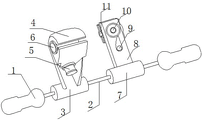
Fig. 1 is a schematic view of the overall structure of a wire damper anti-skid device according to the present invention.
Fig. 2 is a schematic view of the thread locking mechanism and the installation position of the preformed armor rods on the conducting wires of the operation box of the anti-slip device for the conducting wire shockproof hammer according to the present invention.
Fig. 3 is a schematic view of the overall installation position of a wire damper antiskid device according to the present invention.
Fig. 4 is a schematic structural diagram of a ferrule of a wire stockbridge damper antiskid device according to the present invention.
Fig. 5 is a schematic view of the installation of the ferrule and the preformed armor rods of the wire damper antiskid device of the present invention.
Fig. 6 is a schematic structural view of an anti-slip mechanism of the wire damper anti-slip device according to the present invention.
FIG. 7 is a schematic view of the installation position of the anti-slip mechanism of the anti-slip device of the wire damper on the connecting plate and the ratchet wheel.
FIG. 8 is a schematic view of the ratchet structure of the wire damper anti-slip device of the present invention.
Fig. 9 is a schematic view of an anti-slip structure of an anti-slip device of a wire damper according to the present invention.
In the figure: 1. the anti-skidding cable comprises a shockproof hammer 2, a steel strand 3, a first erection sleeve 4, a cable locking mechanism 5, a locking bolt 6, a clamping sleeve 601, a wire guide hole 602, a pre-stranding hole 7, a second erection sleeve 8, a connecting plate 9, a pawl 10, a ratchet 101, a rotating shaft 102, a ratchet 11, an anti-skidding mechanism 1101, an anti-skidding upper plate 1102, an anti-skidding lower plate 1103, a wire arranging groove 12, a wire 13, a pre-stranding wire 14, a suspension clamp 15, an insulator 16, a connecting tower 17, an anti-skidding head 18 and anti-skidding raised lines.
Detailed Description
The invention is further described below with reference to the accompanying drawings.
Example 1
As shown in fig. 1-9, a wire damper antiskid device comprises a damper 1, a wire locking mechanism 4 and an antiskid mechanism 11, wherein a steel strand 2 is arranged on the right side of the damper 1, a first erection sleeve 3 is arranged on the right side of the steel strand 2, the wire locking mechanism 4 is arranged above the first erection sleeve 3, a locking bolt 5 is arranged in the middle of the lower end of the wire locking mechanism 4, a clamping sleeve 6 is arranged in the middle of the upper portion of the left side and the right side of the wire locking mechanism 4, a wire guide hole 601 is arranged on the inner circumference of the clamping sleeve 6, six pre-twisted wire holes 602 are uniformly arranged on the outer circumferential surface, the pre-twisted wire 13 passes through the clamping sleeve 6 to be wound and fixed on a wire 12 through the pre-twisted wire holes 602, a second erection sleeve 7 is arranged on the right side of the first erection sleeve 3, a connecting plate 8 is arranged above the second erection sleeve 7, a pawl 9 is arranged above the middle of the connecting plate 8, the ratchet 9 is installed on the connecting plate 8 through a bearing, a ratchet 10 is arranged above the ratchet 9, the ratchet 10 is installed on the connecting plate 8 through a rotating shaft 101, ratchets 102 are arranged on the outer circumference of the ratchet 10, an anti-skid mechanism 11 is arranged at the other end of the connecting plate 8 corresponding to the rotating shaft 101 of the ratchet 10, the anti-skid mechanism 11 comprises an anti-skid upper plate 1101 and an anti-skid lower plate 1102, semicircular wire arranging grooves 1103 are respectively arranged on the inner sides of the middle parts of the anti-skid upper plate 1101 and the anti-skid lower plate 1102, the upper end and the lower end of the anti-skid mechanism 11 are fixed on the connecting plate 8 through screws, an anti-skid head 17 is arranged at the other end of the rotating shaft 101 on the ratchet 10, the anti-skid head 17 penetrates through the semicircular wire arranging grooves 1103 on the anti-skid upper plate 1101 and is installed on the rotating shaft 101 through a bearing, an anti-skid convex strip 18 is arranged at the middle part of the anti-skid head 17, and a suspension wire clamp 14 is arranged on the wire 12, a connecting pole tower 16 is arranged above the suspension clamp 14, three insulators 15 are uniformly arranged on the connecting pole tower 16, and the vibration dampers 1 are arranged on the left side and the right side of the suspension clamp 14.
The invention adopts a wire locking mechanism and an anti-slip mechanism, wherein the middle part of the lower end of the wire locking mechanism is provided with a locking bolt, the middle parts above the left side and the right side of the wire locking mechanism are provided with a cutting sleeve, the inner circumference of the cutting sleeve is provided with a wire guide hole, the outer circumference surface is evenly provided with six pre-twisted wire holes, the locking bolt is firstly screwed out, the cutting sleeve is arranged at the left side and the right side of the locking mechanism, a wire passes through the wire guide hole in the cutting sleeve, then the wire is arranged in the wire locking mechanism, the pre-twisted wire passes through the pre-twisted wire hole on the cutting sleeve to be wound and fixed on the wire, the engaging force between the wire locking mechanism and the wire is increased, then the locking bolt is screwed, thus the wire is fixed in the locking mechanism, the wire cannot slide or move in the locking mechanism, because the wire locking mechanism is arranged in a first erection sleeve by casting, the anti-vibration is realized, the first erection sleeve and a second erection sleeve are arranged on the steel twisted wire by casting, therefore, the vibration damper can be stably fixed on the steel twisted wire, the vibration damper cannot displace relative to the lead, and the vibration damper is high in practicability and convenient to install and use; the invention adopts an antiskid mechanism, the antiskid mechanism comprises an antiskid upper plate and an antiskid lower plate, the inner sides of the middle parts of the antiskid upper plate and the antiskid lower plate are respectively provided with a semicircular wire placing groove, the two semicircular wire placing grooves clamp a wire, then the upper end and the lower end of the whole antiskid mechanism are fixed on a connecting plate through screws, then a ratchet wheel is rotated, the ratchet wheel drives a rotating shaft to rotate so as to drive an antiskid head to rotate, the antiskid head moves towards the inner part of the wire placing groove on the antiskid upper plate and further locks the wire, an antiskid raised line on the surface of the antiskid head is coated with an antiskid coating to increase friction force, further, when the wire is vibrated under the action of wind power, the antiskid mechanism is prevented from displacing relative to the wire, the ratchet on the ratchet wheel is matched with a pawl for use, the rotating shaft and the antiskid head can be completely clamped, the phenomenon that the holding force of the wire is insufficient due to the loosening of the rotating shaft and the antiskid head is prevented from causing the antiskid mechanism to slide relative to the wire, thereby effectively preventing the wire accessories such as the vibration damper and the like from sliding; the invention has the advantages of simple structure, convenient installation and use, strong practicability and effective prevention of the sliding of wire accessories such as the vibration damper and the like.
Example 2
As shown in fig. 1-9, a conductor damper antiskid device comprises a damper 1, a cable locking mechanism 4 and an antiskid mechanism 11, wherein a steel strand 2 is arranged on the right side of the damper 1, a first erection sleeve 3 is arranged on the right side of the steel strand 2, the cable locking mechanism 4 is arranged above the first erection sleeve 3, a locking bolt 5 is arranged in the middle of the lower end of the cable locking mechanism 4, a clamping sleeve 6 is arranged in the middle of the upper portion of the left side and the right side of the cable locking mechanism 4, conductor holes 601 are arranged on the inner circumference of the clamping sleeve 6, six pre-twisted wire holes 602 are uniformly arranged on the outer circumferential surface, a pre-twisted wire 13 passes through the clamping sleeve 6 through the pre-twisted wire holes 602 and is wound and fixed on a conductor 12, a second erection sleeve 7 is arranged on the right side of the first erection sleeve 3, a connecting plate 8 is arranged above the second erection sleeve 7, a pawl 9 is arranged above the middle portion of the connecting plate 8, the ratchet 9 is installed on the connecting plate 8 through a bearing, a ratchet 10 is arranged above the ratchet 9, the ratchet 10 is installed on the connecting plate 8 through a rotating shaft 101, ratchets 102 are arranged on the outer circumference of the ratchet 10, an anti-skid mechanism 11 is arranged at the other end of the connecting plate 8 corresponding to the rotating shaft 101 of the ratchet 10, the anti-skid mechanism 11 comprises an anti-skid upper plate 1101 and an anti-skid lower plate 1102, semicircular wire placing grooves 1103 are respectively arranged at the inner sides of the middle parts of the anti-skid upper plate 1101 and the anti-skid lower plate 1102, the upper end and the lower end of the anti-skid mechanism 11 are fixed on the connecting plate 8 through screws, an anti-skid head 17 is arranged at the other end of the rotating shaft 101 on the ratchet 10, the anti-skid head 17 penetrates through the semicircular wire placing grooves 1103 on the anti-skid upper plate 1101 and is installed on the rotating shaft 101 through a bearing, an anti-skid convex strip 18 is arranged at the middle part of the anti-skid head 17, a suspension wire 14 is arranged on the wire 12, a connecting pole tower 16 is arranged above the suspension clamp 14, three insulators 15 are evenly arranged on the connecting pole tower 16, and the vibration dampers 1 are arranged on the left side and the right side of the suspension clamp 14.
For better effect, steel strand 2 run through first erects sleeve 3 and second and erects the stockbridge damper 1 of sleeve 7 intercommunication both sides, stockbridge damper 1, first erects sleeve 3 and second and erects sleeve 7 and install on steel strand 2 through the casting, book-locking mechanism 4 install on first erectting sleeve 3 through the casting, connecting plate 8 install at the second and erects sleeve 7 through the casting, adopt the fixed relevant part of casting mode, can improve holistic intensity performance and aesthetic property, can adapt to complicated abominable meteorological condition for a long time, increase of service life saves the cost of changing.
For better effect, the wire hole 601 and the preformed armor rods hole 602 are both non-threaded through holes, so that the wires and the preformed armor rods can conveniently pass through the wire hole 601 and the preformed armor rods hole 602, the installation is convenient and fast, the time is saved, and the working efficiency is improved.
For better effect, the antiskid convex 18 on cover one deck anti-skidding coating, increase the frictional force with the wire contact surface for the wire is more firm in putting the wire casing, reaches the stockbridge damper and can not produce the displacement relatively the wire, prevents the gliding effect of stockbridge damper, when the wire receives wind-force effect and takes place the vibration, continuously carries out the protection of taking precautions against earthquakes to the wire, reduces the emergence of accident.
For better effect, book sewing mechanism inside set up the through-hole that the diameter equals the wire guide diameter of cutting ferrule to the rectangular channel has been seted up to the outside, incompletely confined design for the wire is placed in the book sewing mechanism swiftly convenient, does not need to use special tool, therefore whole device installation convenient to use, the practicality is strong.
In order to achieve better effect, the ratchet wheel, the ratchet and the pawl are used in a matched mode, the size of the pawl is equal to that of the ratchet, and therefore the pawl can completely clamp the ratchet on the ratchet wheel, the ratchet cannot be reversed and can only rotate towards one direction, a wire can be locked, and sliding of accessories of the wire such as a vibration damper is effectively prevented.
The invention adopts a wire locking mechanism and an anti-slip mechanism, wherein the middle part of the lower end of the wire locking mechanism is provided with a locking bolt, the middle parts above the left side and the right side of the wire locking mechanism are provided with a cutting sleeve, the inner circumference of the cutting sleeve is provided with a wire guide hole, the outer circumference surface is evenly provided with six pre-twisted wire holes, the locking bolt is firstly screwed out, the cutting sleeve is arranged at the left side and the right side of the locking mechanism, a wire passes through the wire guide hole in the cutting sleeve, then the wire is arranged in the wire locking mechanism, the pre-twisted wire passes through the pre-twisted wire hole on the cutting sleeve to be wound and fixed on the wire, the engaging force between the wire locking mechanism and the wire is increased, then the locking bolt is screwed, thus the wire is fixed in the locking mechanism, the wire cannot slide or move in the locking mechanism, because the wire locking mechanism is arranged in a first erection sleeve by casting, the anti-vibration is realized, the first erection sleeve and a second erection sleeve are arranged on the steel twisted wire by casting, therefore, the vibration damper can be stably fixed on the steel twisted wire, the vibration damper cannot displace relative to the lead, and the vibration damper is high in practicability and convenient to install and use; the invention adopts an antiskid mechanism, the antiskid mechanism comprises an antiskid upper plate and an antiskid lower plate, the inner sides of the middle parts of the antiskid upper plate and the antiskid lower plate are respectively provided with a semicircular wire placing groove, the two semicircular wire placing grooves clamp a wire, then the upper end and the lower end of the whole antiskid mechanism are fixed on a connecting plate through screws, then a ratchet wheel is rotated, the ratchet wheel drives a rotating shaft to rotate so as to drive an antiskid head to rotate, the antiskid head moves towards the inner part of the wire placing groove on the antiskid upper plate and further locks the wire, an antiskid raised line on the surface of the antiskid head is coated with an antiskid coating to increase friction force, further, when the wire is vibrated under the action of wind power, the antiskid mechanism is prevented from displacing relative to the wire, the ratchet on the ratchet wheel is matched with a pawl for use, the rotating shaft and the antiskid head can be completely clamped, the phenomenon that the holding force of the wire is insufficient due to the loosening of the rotating shaft and the antiskid head is prevented from causing the antiskid mechanism to slide relative to the wire, thereby effectively preventing the lead accessories such as the vibration damper and the like from sliding; the invention has the advantages of simple structure, convenient installation and use, strong practicability and effective prevention of the sliding of wire accessories such as the vibration damper and the like.
Claims (3)
1. The utility model provides a wire stockbridge damper antiskid, it includes stockbridge damper, locking wire mechanism and anti-skidding mechanism, its characterized in that: the steel strand is arranged on the right side of the shockproof hammer, a first erection sleeve is arranged on the right side of the steel strand, a wire locking mechanism is arranged above the first erection sleeve, a locking bolt is arranged in the middle of the lower end of the wire locking mechanism, cutting sleeves are arranged in the middle of the upper portions of the left side and the right side of the wire locking mechanism, wire guide holes are formed in the inner circumferences of the cutting sleeves, six pre-strand holes are uniformly formed in the outer circumferential surface of the cutting sleeves, the pre-strand passes through the cutting sleeves through the pre-strand holes to be wound and fixed on the wires, a second erection sleeve is arranged on the right side of the first erection sleeve, a connecting plate is arranged above the second erection sleeve, a pawl is arranged above the middle of the connecting plate, the pawl is mounted on the connecting plate through a bearing, a ratchet wheel is arranged above the pawl, the ratchet wheel is mounted on the connecting plate through a rotating shaft, and ratchets are arranged on the outer circumference of the ratchet wheel, the anti-skidding mechanism comprises an anti-skidding upper plate and an anti-skidding lower plate, semicircular wire grooves are formed in the inner sides of the middle parts of the anti-skidding upper plate and the anti-skidding lower plate, the upper end and the lower end of the anti-skidding mechanism are fixed on the connecting plate through screws, an anti-skidding head is arranged at the other end of the rotating shaft on the ratchet wheel, the anti-skidding head penetrates through the semicircular wire grooves in the anti-skidding upper plate and is mounted on the rotating shaft through a bearing, anti-skidding convex strips are arranged in the middle of the anti-skidding head, suspension wire clamps are arranged on the wires, a connecting pole tower is arranged above the suspension wire clamps, three insulators are uniformly arranged on the connecting pole tower, the vibration dampers are arranged on the left side and the right side of the suspension wire clamps, and steel stranded wires penetrate through the vibration dampers on the two sides communicated with the first erection sleeve and the second erection sleeve, the anti-skidding steel strand wire locking mechanism is characterized in that the anti-skidding hammer, the first erection sleeve and the second erection sleeve are installed on a steel strand wire through casting, the wire locking mechanism is installed on the first erection sleeve through casting, the connecting plate is installed on the second erection sleeve through casting, the wire guide hole and the pre-stranding wire hole are all unthreaded through holes, and the anti-skidding convex strips are covered with a layer of anti-skidding coating.
2. The wire damper anti-slip device of claim 1, wherein: the inside of the book sewing mechanism is provided with a through hole with the diameter equal to that of the wire guide hole of the clamping sleeve, and the outside of the book sewing mechanism is provided with a rectangular groove.
3. The wire damper anti-slip device of claim 1, wherein: the ratchet wheel, the ratchet and the pawl are matched for use, and the size of the pawl is equal to that of the ratchet.
Priority Applications (1)
| Application Number | Priority Date | Filing Date | Title |
|---|---|---|---|
| CN201911223092.9A CN111030022B (en) | 2019-12-03 | 2019-12-03 | Wire stockbridge damper antiskid |
Applications Claiming Priority (1)
| Application Number | Priority Date | Filing Date | Title |
|---|---|---|---|
| CN201911223092.9A CN111030022B (en) | 2019-12-03 | 2019-12-03 | Wire stockbridge damper antiskid |
Publications (2)
| Publication Number | Publication Date |
|---|---|
| CN111030022A CN111030022A (en) | 2020-04-17 |
| CN111030022B true CN111030022B (en) | 2022-06-10 |
Family
ID=70204156
Family Applications (1)
| Application Number | Title | Priority Date | Filing Date |
|---|---|---|---|
| CN201911223092.9A Expired - Fee Related CN111030022B (en) | 2019-12-03 | 2019-12-03 | Wire stockbridge damper antiskid |
Country Status (1)
| Country | Link |
|---|---|
| CN (1) | CN111030022B (en) |
Families Citing this family (1)
| Publication number | Priority date | Publication date | Assignee | Title |
|---|---|---|---|---|
| CN112421250B (en) * | 2020-09-29 | 2024-04-16 | 国网河南省电力公司西平县供电公司 | Low-voltage wire breakage connecting device |
Family Cites Families (10)
| Publication number | Priority date | Publication date | Assignee | Title |
|---|---|---|---|---|
| JP4434981B2 (en) * | 2005-02-10 | 2010-03-17 | 旭電機株式会社 | Twist prevention device, snow accretion and galloping prevention method |
| CN201442229U (en) * | 2009-07-03 | 2010-04-28 | 中冶焦耐(大连)工程技术有限公司 | Adjusting tool for large springs of coke ovens |
| CN202678896U (en) * | 2012-06-08 | 2013-01-16 | 陈进军 | Anti-skid, preformed and shockproof apparatus |
| CN204602826U (en) * | 2015-05-11 | 2015-09-02 | 邯钢集团邯宝钢铁有限公司 | Horizontal type loop wire rope fastener is rolled in a kind of acid |
| CN205512855U (en) * | 2016-04-11 | 2016-08-31 | 上虞市金桥伞业有限公司 | Rotating base and utilize this rotating base's eccentric sun umbrella |
| CN206195305U (en) * | 2016-11-14 | 2017-05-24 | 尚梦雨 | Novel damper antiskid device |
| CN208640894U (en) * | 2017-09-13 | 2019-03-26 | 张帆 | A kind of high-frequency surgery electric knife rack |
| CN207459527U (en) * | 2017-11-27 | 2018-06-05 | 国家电网公司 | A kind of 10kV arrester handcarts special operating tool |
| CN207559509U (en) * | 2017-12-06 | 2018-06-29 | 江苏曼龙科技有限公司 | A kind of overhead power transmission conducting wire stockbridge damper |
| CN207648359U (en) * | 2017-12-22 | 2018-07-24 | 新乡职业技术学院 | A kind of electronic equipment base device |
-
2019
- 2019-12-03 CN CN201911223092.9A patent/CN111030022B/en not_active Expired - Fee Related
Also Published As
| Publication number | Publication date |
|---|---|
| CN111030022A (en) | 2020-04-17 |
Similar Documents
| Publication | Publication Date | Title |
|---|---|---|
| CN111030022B (en) | Wire stockbridge damper antiskid | |
| CN108598998B (en) | Overhead ground wire stockbridge damper resetting means | |
| CN103023238A (en) | Generator stator winding paint dipping clamp | |
| CN201289991Y (en) | Vibration insulation hammer | |
| CN202167815U (en) | Preformed vibration-proof hammer | |
| CN212210436U (en) | Damper for high-voltage overhead line convenient to assemble | |
| CN216413864U (en) | A tensioner bullwheel for electric power installation | |
| CN204290226U (en) | Energy-saving stockbridge damper | |
| CN210517734U (en) | Anti-slip clamping plate for anti-vibration hammer | |
| CN112968412B (en) | All-insulation phase color preformed armor rod | |
| CN202678896U (en) | Anti-skid, preformed and shockproof apparatus | |
| CN210669464U (en) | Anti-vibration hammer capable of preventing wires from being abraded | |
| CN211377402U (en) | Overhead line installation tensioner bullwheel | |
| CN210669463U (en) | Anti-vibration hammer capable of preventing wires from being abraded | |
| CN210957722U (en) | Strain clamp suitable for lightning conductor | |
| CN210490393U (en) | Strain clamp | |
| CN204012590U (en) | Stockbridge damper | |
| CN110601117A (en) | Anti-slip clamping plate for anti-vibration hammer | |
| CN203660473U (en) | Anti-slip vibration-proof hammer | |
| CN205429654U (en) | Wedge type aluminum alloy high -voltage cable strain insulator tension disk | |
| CN206370669U (en) | A kind of Multifunctional aluminium alloy wire clamp | |
| CN217182922U (en) | Low-voltage power generation access support | |
| CN220797115U (en) | Variable-pitch parallel groove clamp | |
| CN218415748U (en) | Insulator shockproof fast-assembling fastener | |
| CN219627273U (en) | Municipal administration road bridge cable fixed knot constructs |
Legal Events
| Date | Code | Title | Description |
|---|---|---|---|
| PB01 | Publication | ||
| PB01 | Publication | ||
| SE01 | Entry into force of request for substantive examination | ||
| SE01 | Entry into force of request for substantive examination | ||
| GR01 | Patent grant | ||
| GR01 | Patent grant | ||
| CF01 | Termination of patent right due to non-payment of annual fee | ||
| CF01 | Termination of patent right due to non-payment of annual fee |
Granted publication date: 20220610 |