Indirect tire pressure monitoring system and method
Technical Field
The invention belongs to the technical field of automotive electronics, and particularly relates to an indirect tire pressure monitoring system and method.
Background
Since the birth of the first automobile in the world, the life, work and other aspects of human beings have changed greatly. The automobile is changed from a simple transportation tool to an indispensable part in human life, and the requirement of people on the safety of the automobile is continuously improved. The tire is used as the only component in contact with the ground in the whole vehicle, is closely related to the safety of the whole vehicle, and can cause great threat to the life safety of drivers and passengers due to tire burst. Statistics show that the proportion of the tire burst reasons in the traffic accident is as high as 60%, and if the vehicle speed exceeds 160 km/h, the survival probability of the tire burst of the front wheel is almost zero. 75% of the flat tires are caused by insufficient tire pressure, and when the tire pressure is insufficient, the side surfaces of the tires are bent due to compression, so that the temperature of the tires is increased to cause flat tires.
The conventional common tire pressure monitoring system acquires tire pressure by installing a sensor with a wireless transmitting function in a tire, is called as a direct tire pressure monitoring system and is divided into an external type and a built-in type, and part of the direct tire pressure monitoring system also supports acquisition of temperature information in the tire. The direct tire pressure monitoring system has the following disadvantages:
1. the direct tire pressure monitoring needs more hardware support, four tire pressure sensors with batteries and wireless transmission modules, a tire pressure monitoring receiving and displaying device and an alarm signal transmission line, and has higher cost (about 250 units and 500 units per vehicle);
2. the battery needs to be replaced regularly, the tire is disassembled, installed and calibrated, the sensor needs to be calibrated again, and if the sensor is damaged, the battery needs to be replaced, so that the use cost of a user is increased;
3. the problems of loss, time delay and electromagnetic interference occur in the signal transmission process, and the electric quantity and the abrasion degree of the tire pressure sensor also influence the functional stability.
Disclosure of Invention
The technical problem to be solved by the invention is as follows: an indirect tire pressure monitoring system and method are provided to achieve a stable tire pressure monitoring function without additional hardware support.
The technical scheme adopted by the invention for solving the technical problems is as follows: an indirect tire pressure monitoring system comprises a signal preprocessing module, an angular velocity calculating module, a working condition compensating module, a tire self-adaptive model compensating module, a slip rate calculating module, a traction analyzing module and a tire relative radius difference calculating module which are sequentially connected according to a signal flow direction; the signal input port of the signal preprocessing module is connected with the sensor and used for receiving a sensor signal and filtering the received signal to eliminate noise; the angular velocity calculation module is used for calculating the gear ring angular velocity of the preprocessed signals; the working condition compensation module is used for compensating special working conditions; the tire self-adaptive model compensation module is used for establishing a self-adaptive model according to the tire characteristics or calling a corresponding self-adaptive model according to the specification model of the tire and compensating according to the model to improve the functional precision; the slip rate calculation module is used for calculating the wheel slip rate; the traction analysis module is used for calculating the traction of the wheel end and obtaining the relation between the traction of the wheel end and the wheel slip rate; the signal output port of the tire relative radius difference calculation module is connected with the upper computer and used for calculating the relative radius difference of the current tire, comparing the relative radius difference with the calibration value of the relative radius difference of the tire and outputting a judgment result to the upper computer, so that the tire pressure monitoring function is realized.
According to the scheme, the signal preprocessing module comprises a Butterworth FIR low-pass filter and is used for carrying out event-based interpolation and band-pass filtering on received original wheel speed data, filtering noise spikes and preventing false alarm caused by data loss.
According to the scheme, the working condition compensation module comprises a signal failure compensation module, a vehicle braking compensation module, a vehicle gear shifting compensation module, a vehicle reverse gear compensation module, a vehicle steering compensation module, a vehicle ABS/ESC intervention compensation module, a wheel slip compensation module and a rough road surface compensation module.
The monitoring method based on the indirect tire pressure monitoring system comprises the following steps:
s1: the system is electrified and initialized, and the relative radius difference of the tire under the standard tire pressure is calibrated and stored;
s2: receiving and storing information including a raw wheel speed signal and other auxiliary vehicle signals;
s3: calculating the relative radius difference of the current tire according to the information obtained in the step S2, and judging whether the relative radius difference of the current tire is increased compared with the calibrated value of the relative radius difference of the tire under the standard tire pressure obtained in the step S1, if so, determining that the current tire is air-leaking, otherwise, determining that the current tire is air-leaking; and sending the comparison result to an upper computer.
Further, in step S1, the specific steps include:
s11: calibrating the air pressure value after the tire is inflated;
s12: the system is electrified and initialized, and the current tire pressure is set as the standard tire pressure;
s13: checking whether the current tire has the relative radius difference delta r under the standard tire pressurecIf yes, judging whether the storage date of the historical calibration data is larger than or equal to a set value from the current date, and if the storage date of the historical calibration data is smaller than the set value from the current date, not performing calibration; if the storage date of the historical calibration data is larger than or equal to the set value from the current date or no historical data exists, calibrating the relative radius difference delta r of the tire under the standard tire pressurecAnd storing.
Further, in step S3, the specific steps include:
s31: the signal preprocessing module receives an original wheel speed signal and other auxiliary vehicle signals sent by a wheel speed sensor or an ABS/ESC system of a vehicle, event-based interpolation and band-pass filtering are carried out on original wheel speed data through a Butterworth type FIR low-pass filter to filter noise spikes, and the preprocessed signals are sent to the angular speed calculating module;
s32: the angular velocity calculation module calculates the angular velocity of the gear ring according to the received wheel speed signal after preprocessing and sends the angular velocity to the working condition compensation module;
s33: the working condition compensation module judges which working condition the current state of the vehicle belongs to according to the received signal, compensates the received signal according to a corresponding working condition compensation method, and sends the compensated signal to the tire self-adaptive model compensation module;
s34: the tire self-adaptive model compensation module establishes a self-adaptive model according to the received signal and the characteristics of the current tire, or calls a corresponding self-adaptive model according to the specification model of the current tire, compensates the signal obtained in the step S33, and sends the compensated signal to the slip rate calculation module;
s35: the slip rate calculation module calculates the wheel slip rate according to the received signals, the radius of the tire, the acceleration signals and other auxiliary signals and sends the wheel slip rate to the traction analysis module;
s36: the traction analysis module calculates wheel end traction according to the received signals and the torque signals, obtains the relationship between the wheel end traction and the wheel slip rate through a least square method, and sends the relationship to the tire relative radius difference calculation module;
s37: the tire relative radius difference calculation module calculates the relative radius difference delta r of the current tire according to the relationship between the wheel end traction and the wheel slip ratenJudgment of Δ rnWhether it is smaller than the relative radius difference Δ r of the tire at the standard tire pressure obtained in step S1cIf the tire pressure is increased, the current tire is considered to be air-leakage, and an alarm signal is output to the upper computer; if not, the current tire is considered to be airtight, and a judgment result is output to the upper computer;
s38: the upper computer judges whether the received signal is an alarm signal, if so, a calibration command is sent to the system, and the system re-calibrates the relative radius difference delta r of the tire under the standard tire pressure after receiving the calibration commandcAnd storing; if not, the loop is started from step S31.
Further, in step S13, the system couples the wheels according to different speed intervals of the vehicleRelative radius difference delta r of tire under standard tire pressurecThe calibration of (2) is carried out for a plurality of times respectively and stored.
Further, in the step S37, the relative radius difference Δ r of the tire at the standard tire pressurecWhen the calibrated value number of the tire reaches the comparison requirement number of the relative radius difference of the tire, determining delta rnWhether it is smaller than the relative radius difference Δ r of the tire at the standard tire pressure obtained in step S1cIncreasing; relative radius difference delta r of tire under standard tire pressurecWhen the number of the calibrated values of (2) does not satisfy the comparison requirement number of the relative radius difference of the tire, the loop is started from step S1.
The invention has the beneficial effects that:
1. the indirect tire pressure monitoring system can be realized through a low-cost hardware platform and can also be integrated into a vehicle ABS/ESC system, so that the system is high in practicability, multiple in expansion function and good in application portability, and the hardware use cost of a vehicle is effectively reduced; and hardware maintenance is not needed in daily use, so that the maintenance cost of a client is reduced.
2. The invention effectively avoids the defects of signal delay, easy interference and the like of the direct tire pressure monitoring system in the signal transmission process, and enhances the stability of the monitoring function.
Drawings
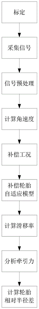
FIG. 1 is a flow chart of an embodiment of the present invention.
Fig. 2 is a computational schematic of an embodiment of the invention.
Fig. 3 is a functional block diagram of a first embodiment of the present invention.
Fig. 4 is a circuit schematic of a first embodiment of the present invention.
Fig. 5 is a functional block diagram of a second embodiment of the present invention.
FIG. 6 is a system diagram of a second embodiment of the present invention
Detailed Description
The present invention will be described in further detail with reference to the accompanying drawings and specific embodiments.
The invention relates to an indirect tire pressure monitoring system which comprises a signal preprocessing module, an angular velocity calculating module, a working condition compensating module, a tire self-adaptive model compensating module, a slip rate calculating module, a traction analyzing module and a tire relative radius difference calculating module which are sequentially connected according to a signal flow direction. The signal input port of the signal preprocessing module is connected with the sensor and used for receiving a sensor signal and filtering the received signal to eliminate noise; the signal preprocessing module comprises a Butterworth FIR low-pass filter and is used for carrying out event-based interpolation and band-pass filtering on the received original wheel speed data, filtering noise spikes and preventing false alarm caused by data loss. The angular velocity calculation module is used for calculating the gear ring angular velocity of the preprocessed signals; the working condition compensation module comprises a signal failure compensation module, a vehicle brake compensation module, a vehicle gear shifting compensation module, a vehicle reverse gear compensation module, a vehicle steering compensation module, a vehicle ABS/ESC intervention compensation module, a wheel slip compensation module and a rough road surface compensation module and is used for compensating various special working conditions corresponding to the modules; the tire self-adaptive model compensation module is used for establishing a self-adaptive model according to the tire characteristics or calling a corresponding self-adaptive model according to the specification model of the tire and compensating according to the model to improve the functional precision; the slip rate calculation module is used for calculating the wheel slip rate; the traction analysis module is used for calculating the traction of the wheel end and obtaining the relation between the traction of the wheel end and the wheel slip rate; the signal output port of the tire relative radius difference calculation module is connected with the upper computer and used for calculating the relative radius difference of the current tire, comparing the relative radius difference with the calibration value of the relative radius difference of the tire and outputting a judgment result to the upper computer, so that the tire pressure monitoring function is realized.
Referring to fig. 3 and 4, embodiment 1 of the present invention is implemented by a separate low-cost hardware platform. The device comprises a data acquisition module, a data analysis module, a data storage module and a data transmission module; the signal input end of the data acquisition module is respectively connected with the signal output end of the sensor and the output end of the vehicle signal system and is used for receiving signals sent by the sensor and the vehicle signal system; the signal input end of the data analysis module is connected with the signal output end of the data acquisition module and is used for receiving the information forwarded by the data acquisition module; the signal receiving and transmitting end of the data analysis module is connected with the signal receiving and transmitting end of the data storage module and used for storing and taking out data into and from the data storage module; the signal input end of the data transmission module is connected with the signal output end of the data analysis module and used for receiving the information sent by the data analysis module and forwarding the information to the upper computer;
STM32F103RCT6 is used as a core board, and a 5V USB interface which is common in vehicles is adopted for supplying power. The hardware part of the scheme has small volume, low power consumption and reliable performance, and meets the design specifications and requirements of standard industrial products; and the cost is low, and the price is within 20 Yuan.
The data acquisition module acquires an original wheel speed signal of the wheel speed sensor through an IO port isolated by an optical coupler, and receives other existing auxiliary signals of the vehicle through the CAN communication module;
the data storage module adopts EEPROM and SD card. The EEPROM is used for storing calibration data and preventing data loss due to power failure; the SD card is used for storing the obtained original wheel speed signal and other auxiliary signals and is used for online tire pressure monitoring or later-stage offline analysis;
the data analysis module comprises a signal preprocessing module, an angular velocity calculation module, a working condition compensation module, a tire self-adaptive model compensation module, a slip rate calculation module, a traction analysis module and a tire relative radius difference calculation module which are sequentially connected according to the signal flow direction, and the tire pressure condition of the current vehicle is obtained by calling, analyzing and calculating the original wheel speed signal and other auxiliary signals in the data storage module;
and a WIFI communication interface and a serial communication interface are provided at the periphery of the data analysis module and are used for transmitting the running state and the related fault information of the data analysis module to upper computer software so that a driver or a maintainer can master the tire pressure condition of the vehicle in real time through a display interface of the upper computer.
Referring to fig. 5 and 6, embodiment 2 of the present invention is integrated in ABS/ESC system software of a vehicle through a related protocol, and implements a tire pressure monitoring function without additional hardware support by receiving an original wheel speed signal provided by the ABS/ESC system and combining with other auxiliary signals such as GPS positioning data of the vehicle.
The method is used for monitoring the pressure drop information of any 1-3 tires in the running speed range from 10km/h to the maximum speed of the vehicle. The detection principle of the invention is that whether the tire leaks air is judged by comparing the relative radius difference of the current wheel with the relative radius difference of the lower wheel under the standard tire pressure. The wheel relative radius difference between the standard tire pressure and the wheel under the standard tire pressure needs to be calibrated before tire pressure monitoring, and on the premise that the tire pressure is guaranteed to be the standard tire pressure, the calibration process is performed spontaneously after the system is reset (completed through a physical key or a human-computer interaction interface), manual intervention is not needed, and the driving function of a vehicle is not influenced. Under normal driving conditions, the duration of the calibration process is between about half an hour and three hours; in the extreme case, a complete calibration process lasts for several days. The calibration data is stored in the EEPROM, and the calibration data cannot be lost after the vehicle is powered off. In the calibration process, the single-wheel and multi-wheel alarm functions are sequentially opened after enough calibration data are acquired, and the whole process does not need manual intervention, so that the interference to a driver is avoided.
Referring to fig. 1, an indirect tire pressure monitoring method includes the steps of:
s1: the system is electrified and initialized, the relative radius difference of the tire under the standard tire pressure is calibrated and stored:
s11: calibrating the air pressure value after the tire is inflated;
s12: the system is electrified and initialized, and the current tire pressure is set as the standard tire pressure;
s13: checking whether the current tire has the relative radius difference delta r under the standard tire pressurecIf yes, judging whether the storage date of the historical calibration data is larger than or equal to a set value from the current date, and if the storage date of the historical calibration data is smaller than the set value from the current date, not performing calibration; if the storage date of the historical calibration data is larger than or equal to the set value from the current date or no historical data exists, respectively comparing the relative radius difference delta r of the tire under the standard tire pressure according to different speed intervals of vehicle runningcAnd calibrating and storing for multiple times.
S2: receiving and storing information including a raw wheel speed signal and other auxiliary vehicle signals;
s3: calculating the relative radius difference of the current tire according to the information obtained in the step S2, and judging whether the relative radius difference of the current tire is increased compared with the calibrated value of the relative radius difference of the tire under the standard tire pressure obtained in the step S1, if so, determining that the current tire is air-leaking, otherwise, determining that the current tire is air-leaking; and sending the comparison result to an upper computer.
S31: the signal preprocessing module receives an original wheel speed signal and other auxiliary vehicle signals sent by a wheel speed sensor or an ABS/ESC system of a vehicle, event-based interpolation and band-pass filtering are carried out on original wheel speed data through a Butterworth type FIR low-pass filter to filter noise spikes, and the preprocessed signals are sent to the angular speed calculating module;
s32: the angular velocity calculation module calculates the angular velocity of the gear ring according to the received wheel speed signal after preprocessing and sends the angular velocity to the working condition compensation module;
s33: the working condition compensation module judges which working condition the current state of the vehicle belongs to according to the received signal, compensates the received signal according to a corresponding working condition compensation method, and sends the compensated signal to the tire self-adaptive model compensation module;
s34: the tire self-adaptive model compensation module establishes a self-adaptive model according to the received signal and the characteristics of the current tire, or calls a corresponding self-adaptive model according to the specification model of the current tire, compensates the signal obtained in the step S33, and sends the compensated signal to the slip rate calculation module;
s35: the slip rate calculation module calculates the wheel slip rate according to the received signals, the radius of the tire, the acceleration signals and other auxiliary signals and sends the wheel slip rate to the traction analysis module;
s36: the traction analysis module calculates wheel end traction according to the received signals and the torque signals, obtains the relationship between the wheel end traction and the wheel slip rate through a least square method, and sends the relationship to the tire relative radius difference calculation module;
s37: the tire relative radius difference calculation module calculates the relative radius difference delta r of the current tire according to the relationship between the wheel end traction and the wheel slip raten(ii) a It is judged at step S1 that the relative radius difference Δ r at the standard tire pressure of the tire is obtainedcWhether the number of calibrated values of (2) has been reachedComparing the required number of the relative radius differences of the tires, and if not, starting the loop from step S1; if it is reached, determining Δ rnWhether the relative radius difference delta r of the tire at the standard tire pressure is largercIf the tire pressure is increased, the current tire is considered to be air-leakage, and an alarm signal is output to the upper computer; if not, the current tire is considered to be airtight, and a judgment result is output to the upper computer;
s38: the upper computer judges whether the received signal is an alarm signal, if so, a calibration command is sent to the system, and the system re-calibrates the relative radius difference delta r of the tire under the standard tire pressure after receiving the calibration commandcAnd storing; if not, the loop is started from step S31.
Referring to fig. 2, taking the right front wheel blow-by as an example, when the right front wheel blow-by reaches a certain degree, the relative radius difference Δ r of the front axle wheels is causedFront sideObviously increasing, and deducing that the front axle has tire leakage; resulting in a relative radius difference deltar of the right wheelRight sideAnd significantly increased, thereby inferring a right front wheel blowby.
In summary, the indirect tire pressure monitoring system and method of the present invention perform data fusion analysis on the original wheel speed signal of the wheel speed sensor and the existing signal of the vehicle to obtain the pressure information of the tire, so as to realize the function of monitoring the tire pressure; the invention can be realized by a low-cost hardware platform, and can also be integrated into a vehicle ABS/ESC system, so that the practicability is strong, the expansion function is multiple, the application portability is good, the hardware maintenance is not needed in daily use, and the hardware cost of the vehicle is effectively reduced; the invention effectively avoids the defects of signal delay, easy interference and the like of the direct tire pressure monitoring system in the signal transmission process, and enhances the stability of the monitoring function.
The above embodiments are only used for illustrating the design idea and features of the present invention, and the purpose of the present invention is to enable those skilled in the art to understand the content of the present invention and implement the present invention accordingly, and the protection scope of the present invention is not limited to the above embodiments. Therefore, all equivalent changes and modifications made in accordance with the principles and concepts disclosed herein are intended to be included within the scope of the present invention.