CN111015640B - A Robot Handling Gripper That Can Realize Precise Positioning of Workpieces - Google Patents
A Robot Handling Gripper That Can Realize Precise Positioning of Workpieces Download PDFInfo
- Publication number
- CN111015640B CN111015640B CN201911393544.8A CN201911393544A CN111015640B CN 111015640 B CN111015640 B CN 111015640B CN 201911393544 A CN201911393544 A CN 201911393544A CN 111015640 B CN111015640 B CN 111015640B
- Authority
- CN
- China
- Prior art keywords
- fixedly connected
- hot forging
- power box
- gear
- forging blank
- Prior art date
- Legal status (The legal status is an assumption and is not a legal conclusion. Google has not performed a legal analysis and makes no representation as to the accuracy of the status listed.)
- Expired - Fee Related
Links
Images



Classifications
-
- B—PERFORMING OPERATIONS; TRANSPORTING
- B25—HAND TOOLS; PORTABLE POWER-DRIVEN TOOLS; MANIPULATORS
- B25J—MANIPULATORS; CHAMBERS PROVIDED WITH MANIPULATION DEVICES
- B25J15/00—Gripping heads and other end effectors
- B25J15/08—Gripping heads and other end effectors having finger members
-
- B—PERFORMING OPERATIONS; TRANSPORTING
- B25—HAND TOOLS; PORTABLE POWER-DRIVEN TOOLS; MANIPULATORS
- B25J—MANIPULATORS; CHAMBERS PROVIDED WITH MANIPULATION DEVICES
- B25J9/00—Program-controlled manipulators
- B25J9/02—Program-controlled manipulators characterised by movement of the arms, e.g. cartesian coordinate type
- B25J9/04—Program-controlled manipulators characterised by movement of the arms, e.g. cartesian coordinate type by rotating at least one arm, excluding the head movement itself, e.g. cylindrical coordinate type or polar coordinate type
-
- B—PERFORMING OPERATIONS; TRANSPORTING
- B25—HAND TOOLS; PORTABLE POWER-DRIVEN TOOLS; MANIPULATORS
- B25J—MANIPULATORS; CHAMBERS PROVIDED WITH MANIPULATION DEVICES
- B25J9/00—Program-controlled manipulators
- B25J9/10—Program-controlled manipulators characterised by positioning means for manipulator elements
- B25J9/102—Gears specially adapted therefor, e.g. reduction gears
Landscapes
- Engineering & Computer Science (AREA)
- Robotics (AREA)
- Mechanical Engineering (AREA)
- Forging (AREA)
Abstract
本发明属于机械手技术领域,具体的说是一种可以实现工件精确定位的机器人搬运手爪,包括底座、动力箱和定位销,所述底座的上表面转动连接有转动柱;所述转动柱的上表面固连有第一伸缩气缸;所述第一伸缩气缸的弧形面靠近第一伸缩气缸活塞杆的上端面位置固连有水平放置的第二伸缩气缸;所述第二伸缩气缸的活塞杆的端面位置固连有固定壳;所述固定壳的内部滑动连接有动力箱;所述动力箱靠近热锻毛坯位置设有定位销;通过一种可以实现工件精确定位的机器人搬运手爪,有效的适应了热锻齿轮的工艺加工需要,同时保证了热锻毛坯高精度的定位,有效的提高了高精度热锻齿轮的良品率。
The invention belongs to the technical field of manipulators, in particular to a robot handling gripper capable of realizing precise positioning of workpieces, comprising a base, a power box and a positioning pin, and a rotating column is rotatably connected to the upper surface of the base; A first telescopic cylinder is fixedly connected to the upper surface; a horizontally placed second telescopic cylinder is fixedly connected to the arc surface of the first telescopic cylinder near the upper end face of the piston rod of the first telescopic cylinder; the piston of the second telescopic cylinder A fixed shell is fixedly connected to the end face of the rod; a power box is slidably connected to the inside of the fixed shell; a positioning pin is arranged on the power box near the hot forging blank; a robot handling gripper that can realize precise positioning of the workpiece, It effectively meets the processing needs of hot forging gears, and at the same time ensures the high-precision positioning of hot forging blanks, and effectively improves the yield of high-precision hot forging gears.
Description
技术领域technical field
本发明属于机械手技术领域,具体的说是一种可以实现工件精确定位的机器人搬运手爪。The invention belongs to the technical field of manipulators, in particular to a robot handling gripper which can realize precise positioning of workpieces.
背景技术Background technique
机器人手爪是可以实现类似人手功能的机器人部件,机器人手爪是用来握持工件或工具的部件,是重要的执行机构之一,根据机器人所握持的工件形状不同,手爪可分为多种类型,主要可分为三类:机械手爪,又称为机械夹钳,包括2指、3指和变形指,包括磁吸盘、焊枪等的特殊手爪,通用手爪,包括2指到5指。The robot gripper is a robot part that can realize functions similar to the human hand. The robot gripper is a part used to hold the workpiece or tool and is one of the important actuators. According to the shape of the workpiece held by the robot, the gripper can be divided into There are many types, which can be mainly divided into three categories: mechanical grippers, also known as mechanical clamps, including 2-finger, 3-finger and deformed fingers, special grippers including magnetic chucks, welding guns, etc., general grippers, including 2-finger to 5 fingers.
现有技术中,机器人手爪夹取热锻毛坯时,不同的夹紧板之间移动精度较低,使得夹紧力度不平衡,进而导致热锻毛坯的位置精度较低,且无定位销的插接定位作用,一方面使得手爪无法小幅度调整,另一方面无检修反馈,容易导致产品批量性加工不良等问题。In the prior art, when the robot hand grips the hot forging blank, the movement accuracy between different clamping plates is low, which makes the clamping force unbalanced, which in turn leads to low positional accuracy of the hot forging blank, and there is no positioning pin. The plug-in positioning function, on the one hand, makes it impossible to adjust the gripper in a small amount, and on the other hand, there is no maintenance feedback, which easily leads to problems such as poor batch processing of products.
鉴于此,为了克服上述技术问题,本公司设计研发了一种可以实现工件精确定位的机器人搬运手爪,解决了上述技术问题。In view of this, in order to overcome the above technical problems, our company has designed and developed a robot handling gripper that can realize precise positioning of the workpiece, and solved the above technical problems.
发明内容SUMMARY OF THE INVENTION
为了弥补现有技术的不足,解决现有技术中,机器人手爪夹取热锻毛坯时,不同的夹紧板之间移动精度较低,使得夹紧力度不平衡,进而导致热锻毛坯的位置精度较低,且无定位销的插接定位作用,一方面使得手爪无法小幅度调整,另一方面无检修反馈,容易导致产品批量性加工不良等问题,本发明提出的一种可以实现工件精确定位的机器人搬运手爪。In order to make up for the deficiencies of the prior art, in the prior art, when the robot gripper grips the hot forging blank, the moving precision between different clamping plates is low, which makes the clamping force unbalanced, which in turn leads to the position of the hot forging blank. The accuracy is low, and there is no insertion and positioning function of the positioning pin. On the one hand, the gripper cannot be adjusted in a small range. On the other hand, there is no maintenance feedback, which easily leads to problems such as poor batch processing of products. The method proposed by the present invention can realize the workpiece Precisely positioned robotic handling grippers.
本发明解决其技术问题所采用的技术方案是:本发明所述的一种可以实现工件精确定位的机器人搬运手爪,包括底座、动力箱和定位销,所述底座的上表面转动连接有转动柱;所述转动柱的上表面固连有第一伸缩气缸;所述第一伸缩气缸的弧形面靠近第一伸缩气缸活塞杆的上端面位置固连有水平放置的第二伸缩气缸;所述第二伸缩气缸的活塞杆的端面位置固连有固定壳;所述固定壳的内部开设有第一空腔;所述第一空腔的内部于固定壳的底部位置滑动连接有动力箱;所述动力箱的内部开设有第二空腔;所述动力箱的上表面靠近动力箱背离第二伸缩气缸的一侧侧面位置开设有第一转动孔;所述第一转动孔的数量为二,且左右对称设置;两个所述第一转动孔的内部均转动连接有第一传动柱;两个所述第一传动柱的上表面均固连有第一齿轮,两个第一齿轮大小相等且相互之间啮合;两个所述第一传动柱的下表面于第二空腔的内部位置分别固连有第一电机和第二电机;所述第一电机和第二电机之间正反方式运转,且均与动力箱相固连;两个所述第一传动柱的弧形面于第一齿轮和动力箱之间位置均固连有第一连杆;所述动力箱的侧面于第一连杆位置开设有传动孔;且第一连杆穿过传动孔均延伸至动力箱的外部;所述第一连杆远离动力箱的一侧端面位置均铰接有第二连杆;两个所述第二连杆均为“V”形结构设计;所述动力箱于传动孔一侧侧面中间位置固连有固定块;所述固定块的上表面铰接有两个对称设置的第三连杆;两个所述第三连杆分别与对应的第二连杆之间相互铰接;两个所述第二连杆之间位置共同夹有同一个热锻毛坯;所述动力箱靠近热锻毛坯位置设有定位销;工作时,由于齿轮需要有具有较高的硬度、耐磨性以及精度要求,因此现有技术中有通过热精锻方式进行制作齿轮,制作的过程中为了保证齿轮加工品质,因此需要将热锻毛坯的加热装置和锻造模具置于同一真空罩内,由于真空罩内的温度较高且要求真空环境,因此无法通过人工方式进行进行热锻毛坯的取放,故需要通过机器人手爪进行搬运,使得加热装置内的热锻毛坯可以转运到锻造模具内,由于热精锻齿轮需要较高的定位精度以满足高效和高精度的加工需求,因此需要实现机器人手爪的高精度定位功能,当需要转运加热装置内的毛坯时,首先使得转动柱在底座内转动,同时配合第一伸缩气缸和第二伸缩气缸的活塞杆顶出和内收,使得热锻毛坯位于两个第二连杆之间位置,然后分别正反向转动对应的第一电机和第二电机,第一电机和第二电机带动对应的第一传动柱转动,进而带动第一传动柱上方的两个第一齿轮转动,两个第一齿轮之间相互啮合且传动比为一,因此可以有效的带动两个第一连杆的转动,通过第一连杆上均铰接第二连杆,且第二连杆的表面均铰接第三连杆,且两个第三连杆的另一端均共同铰接于同一个固定块的表面,因此两个第一齿轮通过啮合方式,实现了两个第二连杆的同步相向或相背方向移动,且移动距离同步相等,因此在第二连杆在夹紧热锻毛坯时,可以保证两个第二连杆的定位始终保持对称,进而实现更高的夹紧精度要求,通过设置定位销,且定位销和热精锻的模具的定位孔对应插接,且定位孔的口部为喇叭状结构,保证每次放置热锻毛坯时,可以进行有效的定位同时可以进行小幅度调整,同时如定位销未有效的插接于对应的定位孔内时,机器人搬运手爪会停止运转,提醒检修,通过一种可以实现工件精确定位的机器人搬运手爪,有效的解决了现有技术中,机器人手爪夹取热锻毛坯时,不同的夹紧板之间移动精度较低,使得夹紧力度不平衡,进而导致热锻毛坯的位置精度较低,且无定位销的插接定位作用,一方面使得手爪无法小幅度调整,另一方面无检修反馈,容易导致产品批量性加工不良等问题,有效的适应了热锻齿轮的工艺加工需要,同时保证了热锻毛坯高精度的定位,有效的提高了高精度热锻齿轮的良品率。The technical solution adopted by the present invention to solve the technical problem is as follows: a robot handling gripper that can realize precise positioning of the workpiece according to the present invention includes a base, a power box and a positioning pin, and the upper surface of the base is rotatably connected with a rotating A first telescopic cylinder is fixedly connected to the upper surface of the rotating column; a horizontally placed second telescopic cylinder is fixedly connected to the arc surface of the first telescopic cylinder near the upper end surface of the piston rod of the first telescopic cylinder; A fixed casing is fixedly connected to the end face of the piston rod of the second telescopic cylinder; a first cavity is opened inside the fixed casing; a power box is slidably connected to the bottom of the fixed casing in the inside of the first cavity; The inside of the power box is provided with a second cavity; the upper surface of the power box is provided with a first rotation hole at a position close to the side of the power box away from the second telescopic cylinder; the number of the first rotation holes is two , and are arranged symmetrically from left to right; a first transmission column is rotatably connected to the inside of the two first rotation holes; a first gear is fixedly connected to the upper surface of the two first transmission columns, and the two first gears are the same size as The lower surfaces of the two first transmission columns are respectively fixed with a first motor and a second motor at the inner position of the second cavity; the first motor and the second motor are directly connected to each other. Operates in the opposite way, and both are fixedly connected with the power box; the arc surfaces of the two first transmission columns are fixedly connected with a first connecting rod at the position between the first gear and the power box; the side surface of the power box A transmission hole is opened at the position of the first connecting rod; and the first connecting rod extends to the outside of the power box through the transmission hole; the second connecting rod is hinged on the end face of the first connecting rod away from the power box; The two second connecting rods are of "V"-shaped structure design; the power box is fixedly connected with a fixed block at the middle position of one side of the transmission hole; the upper surface of the fixed block is hinged with two symmetrically arranged first rods. Three connecting rods; the two third connecting rods are hinged with the corresponding second connecting rods; the same hot forging blank is sandwiched between the two second connecting rods; the power box is close to The position of the hot forging blank is provided with a positioning pin; during operation, since the gear needs to have high hardness, wear resistance and precision requirements, the prior art is to manufacture the gear by hot precision forging. During the manufacturing process, in order to ensure Due to the high quality of gear processing, it is necessary to place the heating device of the hot forging blank and the forging die in the same vacuum hood. Due to the high temperature in the vacuum hood and the requirement of a vacuum environment, it is impossible to manually pick and place the hot forging blank. Therefore, it needs to be transported by the robot gripper, so that the hot forging blank in the heating device can be transferred to the forging die. Since the hot precision forging gear needs high positioning accuracy to meet the processing requirements of high efficiency and high precision, it is necessary to realize the robot hand. The high-precision positioning function of the claw, when it is necessary to transfer the blank in the heating device, firstly make the rotating column rotate in the base, and at the same time cooperate with the piston rod of the first telescopic cylinder and the second telescopic cylinder to push out and retract, so that the hot forging blank is It is located between the two second connecting rods, and then the corresponding first motor and second motor are rotated forward and reverse respectively. The first motor and the second motor drive the corresponding first transmission column to rotate. The two first gears above the first transmission column are driven to rotate, the two first gears are meshed with each other and the transmission ratio is one, so the rotation of the two first connecting rods can be effectively driven. Both are hinged to the second link, and the surfaces of the second link are both hinged to the third link, and the other ends of the two third links are both hinged to the surface of the same fixed block, so the two first gears are meshed In this way, the synchronous movement of the two second connecting rods in the opposite or opposite directions is realized, and the moving distances are synchronously equal. Therefore, when the second connecting rod clamps the hot forging blank, the positioning of the two second connecting rods can always be guaranteed. Maintain symmetry to achieve higher clamping accuracy requirements. By setting positioning pins, the positioning pins and the positioning holes of the hot precision forging die are correspondingly inserted, and the mouth of the positioning holes is a horn-shaped structure to ensure that each time the heat is placed. When forging the blank, it can be effectively positioned and adjusted in small steps. At the same time, if the positioning pin is not effectively inserted into the corresponding positioning hole, the robot handling claw will stop running, reminding the maintenance, and the workpiece can be realized through a method. The precise positioning of the robot handling gripper effectively solves the problem that in the prior art, when the robot gripper grips the hot forging blank, the moving precision between different clamping plates is low, which makes the clamping force unbalanced, which in turn leads to hot forging. The positional accuracy of the blank is low, and there is no insertion and positioning function of the positioning pin. On the one hand, the gripper cannot be adjusted in a small amount. The processing needs of the gears, while ensuring the high-precision positioning of the hot-forging blanks, effectively improving the yield of high-precision hot-forging gears.
优选的,所述定位销的下表面倒有斜角;所述定位销的下表面滚动连接有一个第一钢珠;所述定位销的斜角所在的面滚动连接有均匀布置的第二钢珠;以定位销的轴线为中心,所述第二钢珠所在的最大轮廓外圆直径小于定位销的直径;工作时,当定位销开始插接于定位孔内时,由于位置存在小的偏差,因此定位销可以通过定位孔喇叭状的开口划入到定位孔内,但是当定位销长时间反复插接于定位孔,定位销的底部会和定位孔喇叭状的开口反复摩擦,一方面容易造成定位销的划伤或断裂,另一方面也会使得定位机构运动定位过程出现摩擦异响,不利于长期高效的加工需求,因此通过在定位销的表面设置第一钢柱和均匀布置的第二钢柱,定位销在插接入定位孔喇叭状的开口位置时,有效的实现了定位销和定位孔的滚动摩擦接触,减少了摩擦力,避免了接触面的划伤磨损,实现了定位的高效运转。Preferably, the lower surface of the positioning pin is beveled; a first steel ball is rollingly connected to the lower surface of the positioning pin; the second steel ball that is evenly arranged is rollingly connected to the surface where the bevel of the positioning pin is located; Taking the axis of the locating pin as the center, the outer diameter of the largest outline of the second steel ball is smaller than the diameter of the locating pin; during operation, when the locating pin begins to be inserted into the locating hole, due to the small deviation of the position, the positioning The pin can be inserted into the positioning hole through the horn-shaped opening of the positioning hole, but when the positioning pin is repeatedly inserted into the positioning hole for a long time, the bottom of the positioning pin will repeatedly rub against the horn-shaped opening of the positioning hole, which is easy to cause the positioning pin. On the other hand, it will also cause abnormal friction noise during the movement and positioning of the positioning mechanism, which is not conducive to the long-term and efficient processing requirements. Therefore, by setting the first steel column and the evenly arranged second steel column on the surface of the positioning pin When the positioning pin is inserted into the horn-shaped opening of the positioning hole, the rolling friction contact between the positioning pin and the positioning hole is effectively realized, the friction force is reduced, the scratch and wear of the contact surface is avoided, and the efficient operation of positioning is realized. .
优选的,所述动力箱滑动连接于固定壳;所述第一空腔的内部于固定壳的侧壁和动力箱的侧壁之间位置固连有均匀布置的第一弹簧;工作时,由于动力箱在第一空腔内并与固定壳滑动连接,因此在定位销插接入定位孔实现定位之前,会出现动力箱在固定壳的内部前后左右窜动的现象,进而会影响第二连杆位置定位,以及对热锻毛坯进行快速有效的夹紧,因此通过设置在固定壳和动力箱之间位置固连均匀布置的第一弹簧,通过第一弹簧的弹力作用,可以使得固定壳在未受到外力的条件下,基本位于第一空腔的中间位置,因此可以保证定位销的初始位置精度,同时也可以避免动力箱在第一空腔的内部窜动,造成动力箱和固定壳的侧壁之间产生碰撞,影响运动机构的稳定性以及机器人搬运手爪的使用寿命。Preferably, the power box is slidably connected to the fixed casing; the inside of the first cavity is fixedly connected with a first spring that is evenly arranged between the side wall of the fixed casing and the side wall of the power box; during operation, due to The power box is in the first cavity and is slidably connected to the fixed shell. Therefore, before the positioning pin is inserted into the positioning hole for positioning, the power box will move back and forth inside the fixed shell, left and right, which will affect the second connection. Positioning of the rod position and fast and effective clamping of the hot forging blank. Therefore, by arranging the first spring fixedly and evenly arranged between the fixed shell and the power box, the elastic force of the first spring can make the fixed shell in the Under the condition of no external force, it is basically located in the middle position of the first cavity, so the initial position accuracy of the positioning pin can be ensured, and at the same time, the power box can be prevented from moving inside the first cavity, causing the power box and the fixed shell. The collision between the side walls affects the stability of the motion mechanism and the service life of the robot handling gripper.
优选的,所述动力箱的上表面靠近第二伸缩杆位置开设有两个第二转动孔;两个所述第二转动孔的内部均转动连接有第二传动柱;两个所述第二传动柱的上表面分别固连有第二齿轮和第三齿轮;所述第二齿轮和第三齿轮之间相互啮合,且第二齿轮和第三齿轮的传动比为二;两个所述第二传动柱的下表面于第二空腔的内部位置分别固连有第三电机和第四电机,且第三电机与第二齿轮均位于同一个第二传动柱表面;所述第三电机和第四电机之间正反方式运转,且均与动力箱相固连;所述第二齿轮啮合连接有第一齿条;所述第一齿条于热锻毛坯的左侧位置固连有第一限位块;所述固定箱相对于热锻毛坯一侧侧面固连有对称设置的支架;两个所述支架靠近热锻毛坯位置固连有第二限位块;所述第三齿轮啮合连接有第二齿条;所述第二齿条于第一限位块和第二限位块之间位置固连有定位销;所述动力箱的上表面于第一齿条和第二齿条位置均固连有两个导向块;所述第一齿轮和第二齿轮均滑动连接于对应的导向块内;工作时,由于热锻毛坯的形状不圆整或第二连杆夹紧热锻毛坯定位有一定偏差时,会使得热锻毛坯的轴线和定位销的相对基准点存在较大的偏差,因此通过第三电机和第四电机带动第二齿轮和第三齿轮正反向转动,第二齿轮和第三齿轮进而带动第一齿条和第二齿条在导向块的内部滑动,通过在第一齿条的端部位置固连第一限位块,因此可以通过第一齿条带动第一限位块的运动,配合固定的第二限位块,可以实现了热锻毛坯前后左右四个方向的固定,通过第二齿条于第一限位块和第二限位块之间位置固连有定位销,因此滑动的第二齿条可以带动定位销的位置调整,同时由于第二齿轮和第三齿轮的传动比为二,因此可以使得第一齿条的移动距离始终是第二齿条移动距离的两倍,保证了定位销始终位于第一限位块和第二限位块的中间位置,保证了热锻毛坯和定位销相对位置的固定,因此可以满足不同大小热锻毛坯进一步有效夹紧的同时也保证了定位销的定位精度,结构简单,自动化程度高。Preferably, two second rotation holes are opened on the upper surface of the power box near the second telescopic rod; the interiors of the two second rotation holes are rotatably connected with a second transmission column; The upper surface of the transmission column is respectively fixed with a second gear and a third gear; the second gear and the third gear are meshed with each other, and the transmission ratio of the second gear and the third gear is two; The lower surfaces of the two transmission columns are respectively fixed with a third motor and a fourth motor at the inner position of the second cavity, and the third motor and the second gear are located on the same surface of the second transmission column; the third motor and The fourth motor runs in a forward and reverse manner, and both are fixedly connected to the power box; the second gear is meshed and connected with a first rack; the first rack is fixedly connected to the left position of the hot forging blank. a limit block; a symmetrically arranged bracket is fixedly connected to one side of the fixed box relative to the hot forging blank; a second limit block is fixedly connected to the two brackets near the hot forging blank; the third gear meshes A second rack is connected; the second rack is fixedly connected with a positioning pin between the first limit block and the second limit block; the upper surface of the power box is connected to the first rack and the second rack Two guide blocks are fixedly connected at the positions of the bars; the first gear and the second gear are both slidably connected in the corresponding guide blocks; during operation, due to the unrounded shape of the hot forging blank or the clamping heat of the second connecting rod. When there is a certain deviation in the positioning of the forging blank, there will be a large deviation between the axis of the hot forging blank and the relative reference point of the positioning pin. Therefore, the second gear and the third gear are driven to rotate forward and reverse by the third motor and the fourth motor. The second gear and the third gear then drive the first rack and the second rack to slide inside the guide block. By fixing the first limit block at the end of the first rack, it can pass the first rack. Drive the movement of the first limit block and cooperate with the fixed second limit block to realize the fixation of the hot forging blank in four directions: front, back, left, right, and through the second rack between the first limit block and the second limit block. A positioning pin is fixed between the two positions, so the sliding second rack can drive the position adjustment of the positioning pin. At the same time, because the transmission ratio of the second gear and the third gear is two, the moving distance of the first rack can always be Twice the moving distance of the second rack ensures that the positioning pin is always located in the middle of the first limit block and the second limit block, and ensures the relative position of the hot forging blank and the positioning pin. The forging blank is further effectively clamped, and the positioning accuracy of the positioning pin is also ensured, the structure is simple, and the degree of automation is high.
优选的,所述第一限位块、第二限位块和两个第二连杆之间共同连接有同一个热锻毛坯;所述第一限位块和第二限位块相对于热锻毛坯的一侧侧面位置均固连有第一夹板,且第一夹板均为耐高温材料设计;两个所述第二连杆相对于热锻毛坯的一侧侧面位置均开设有滑槽;所述滑槽的内部均滑动连接有第二夹板,且第二夹板均为耐高温材料设计;工作时,当需要对热锻毛坯夹紧时,首先通过第二连杆的转动实现对毛坯的预夹紧,然后通过移动第一限位块使得推动热锻毛坯贴于第二限位块表面,进而与第二限位块之间实现对热锻毛坯的二次限位夹紧,但是由于第一限位块在推动热锻毛坯的过程中,会使得热锻毛坯在第二连杆的表面滑动此一方面摩擦力的作用会增加第一限位块的运动阻力,另一方面滑动过程中也会造成毛坯和第二连杆的损伤,影响加工精度和机器人搬运手爪的使用寿命,且第一限位块、第二限位块和第二连杆直接与高温的热锻毛坯长期反复接触也会不利于运动机构长时间的使用,因此通过在第一限位块和第二限位块相对的于热锻毛坯的一侧侧面固连第一夹板,通过将第一夹板设计为耐高温和导热性较差的材料,可以有效的减少高温对第一限位块和第二限位块的影响,通过在第二连杆的表面开设滑槽,且滑槽的内部滑动连接第二夹板,当第一限位块通过第一夹板推动热锻毛坯移动时,可以直接通过第二夹板在滑槽的内部滑动,实现热锻毛坯的快速无摩擦损伤的移动,且同样第二限位块也可以设计为耐高温和导热性较差的材料,保证了运动机构的长期有效运转。Preferably, the same hot forging blank is commonly connected between the first limit block, the second limit block and the two second connecting rods; the first limit block and the second limit block are relative to the heat A first splint is fixedly connected to one side of the forging blank, and the first splint is designed with a high temperature resistant material; the two second connecting rods are provided with a chute relative to one side of the hot forging blank; The inside of the chute is slidably connected with a second splint, and the second splint is designed with high temperature resistant materials; when working, when the hot forging blank needs to be clamped, firstly, the second connecting rod is rotated to realize the clamping of the blank. Pre-clamp, and then push the hot forging blank to stick to the surface of the second limit block by moving the first limit block, and then realize the secondary limit clamping of the hot forging blank with the second limit block, but due to During the process of pushing the hot forging blank by the first limit block, the hot forging blank will slide on the surface of the second connecting rod. It will also cause damage to the blank and the second connecting rod, which will affect the machining accuracy and the service life of the robot handling gripper, and the first limit block, the second limit block and the second connecting rod are directly connected to the high-temperature hot forging blank for a long time. Repeated contact will also be detrimental to the long-term use of the motion mechanism. Therefore, by fixing the first clamp plate on the side of the first limit block and the second limit block opposite to the hot forging blank, the first clamp plate is designed as Materials with poor high temperature resistance and thermal conductivity can effectively reduce the influence of high temperature on the first limit block and the second limit block. Two clamping plates, when the first limit block pushes the hot forging blank to move through the first clamping plate, it can slide directly inside the chute through the second clamping plate to realize the rapid and frictionless movement of the hot forging blank. The bit block can also be designed as a material with poor high temperature resistance and thermal conductivity, which ensures the long-term and effective operation of the motion mechanism.
优选的,所述第二夹板与对应的滑槽之间位置均固连有两个第二弹簧,且第二弹簧均分别位于滑槽的左右两侧侧面位置;所述第一夹板和第二夹板相对于热锻毛坯一侧侧面位置均为糙面设计;工作时,当将热锻毛坯置于热锻模具内后,由于第二夹板均滑动到滑槽的一端位置,故会影响第二夹板的二次滑动使用时,因此通过在第二夹板和对应的滑槽之间位置固连第二弹簧,且第二弹簧左右对称设置,因此可以有效的实现第二夹板的制动复位,且复位至滑槽的中间位置,保证了可持续工作的能力,且通过将第一夹板和第二夹板相对于热锻毛坯一侧侧面位置均设计为糙面结构,可以避免热锻毛坯的上下滑动,同时也可以保证第一夹板在推动热锻毛坯的时候,热锻毛坯不会在两个第二夹板表面滑动,保证了热锻毛坯质量稳定性。Preferably, two second springs are fixedly connected between the second splint and the corresponding chute, and the second springs are located on the left and right sides of the chute respectively; the first splint and the second The position of the splint relative to the side of the hot forging blank is rough surface design; when the hot forging blank is placed in the hot forging die during operation, since the second splint slides to one end of the chute, it will affect the second When the splint is used for secondary sliding, the second spring is fixed between the second splint and the corresponding chute, and the second spring is arranged symmetrically on the left and right, so the braking and reset of the second splint can be effectively realized, and Reset to the middle position of the chute to ensure the ability to work continuously, and by designing the first clamp plate and the second clamp plate relative to one side of the hot forging blank as a rough surface structure, the up and down sliding of the hot forging blank can be avoided. At the same time, it can also ensure that when the first clamp plate pushes the hot forging blank, the hot forging blank will not slide on the surfaces of the two second clamp plates, thereby ensuring the quality stability of the hot forging blank.
本发明的有益效果如下:The beneficial effects of the present invention are as follows:
1.本发明所述的一种可以实现工件精确定位的机器人搬运手爪,通过设置底座、动力箱和定位销,通过底座的上表面转动连接转动柱,转动柱的上表面固连第一伸缩气缸,第一伸缩气缸的弧形面靠近第一伸缩气缸活塞杆的上端面位置固连水平放置的第二伸缩气缸,第二伸缩气缸的活塞杆的端面位置固连固定壳,固定壳的内部滑动连接动力箱,动力箱的内部设置一对第一齿轮,两个第一齿轮带动第一连杆,第一连杆进而带动第二连杆实现对热锻毛坯的夹紧,且动力箱靠近热锻毛坯位置设有定位销,通过一种可以实现工件精确定位的机器人搬运手爪,有效的解决了现有技术中,机器人手爪夹取热锻毛坯时,不同的夹紧板之间移动精度较低,使得夹紧力度不平衡,进而导致热锻毛坯的位置精度较低,且无定位销的插接定位作用,一方面使得手爪无法小幅度调整,另一方面无检修反馈,容易导致产品批量性加工不良等问题,有效的适应了热锻齿轮的工艺加工需要,同时保证了热锻毛坯高精度的定位,有效的提高了高精度热锻齿轮的良品率。1. A kind of robot handling gripper that can realize precise positioning of the workpiece according to the present invention, by setting the base, the power box and the positioning pin, the upper surface of the base is rotated and connected to the rotating column, and the upper surface of the rotating column is fixedly connected to the first telescopic Cylinder, the arc surface of the first telescopic cylinder is close to the upper end face of the piston rod of the first telescopic cylinder and is fixed to the second telescopic cylinder placed horizontally, and the end face of the piston rod of the second telescopic cylinder is fixed to the fixed shell, and the interior of the fixed shell The power box is slidably connected, a pair of first gears are arranged inside the power box, the two first gears drive the first connecting rod, and the first connecting rod further drives the second connecting rod to clamp the hot forging blank, and the power box is close to Positioning pins are provided at the position of the hot forging blank, and a robot handling gripper that can realize precise positioning of the workpiece effectively solves the problem of the robot gripper moving between different clamping plates in the prior art when the hot forging blank is clamped. The low precision makes the clamping force unbalanced, which in turn leads to low positional accuracy of the hot forging blank, and there is no insertion and positioning function of the positioning pin. This leads to problems such as poor batch processing of products, which effectively meets the processing needs of hot forging gears, and at the same time ensures the high-precision positioning of hot forging blanks, effectively improving the yield of high-precision hot forging gears.
2.本发明所述的一种可以实现工件精确定位的机器人搬运手爪,通过设置第二齿轮、第三齿轮、第一限位块和第二限位块,通过在动力箱的内部设置第二齿轮和第三齿轮,第二齿轮和第三齿轮之间相互啮合,且第二齿轮和第三齿轮的传动比为二,通过第二齿轮带动第一齿条移动,进而带动第一限位块的移动,配合固定的第二限位块,实现对热锻毛坯的有效限位固定,且用过第三齿轮带动第二齿条的移动,进而带动定位销的移动,一方面,实现了热锻毛坯前后左右四个方向的固定,另一方面,第一齿条的移动距离始终是第二齿条移动距离的两倍,保证了定位销始终位于第一限位块和第二限位块的中间位置,保证了热锻毛坯和定位销相对位置的固定,因此可以满足不同大小热锻毛坯有效夹紧的同时也保证了定位销的定位精度,结构简单,自动化程度高。2. According to the present invention, a robot handling gripper that can realize precise positioning of the workpiece is provided by setting the second gear, the third gear, the first limit block and the second limit block, and by setting the first limit block inside the power box. The second gear and the third gear, the second gear and the third gear mesh with each other, and the transmission ratio of the second gear and the third gear is two, the second gear drives the first rack to move, and then drives the first limit The movement of the block cooperates with the fixed second limit block to realize the effective limit and fixation of the hot forging blank, and the third gear is used to drive the movement of the second rack, which in turn drives the movement of the positioning pin. The hot forging blank is fixed in four directions, front, back, left and right. On the other hand, the moving distance of the first rack is always twice that of the second rack, which ensures that the positioning pin is always located at the first limit block and the second limit The middle position of the block ensures that the relative position of the hot forging blank and the positioning pin is fixed, so it can satisfy the effective clamping of hot forging blanks of different sizes and also ensure the positioning accuracy of the positioning pin. The structure is simple and the degree of automation is high.
附图说明Description of drawings
下面结合附图对本发明作进一步说明。The present invention will be further described below in conjunction with the accompanying drawings.
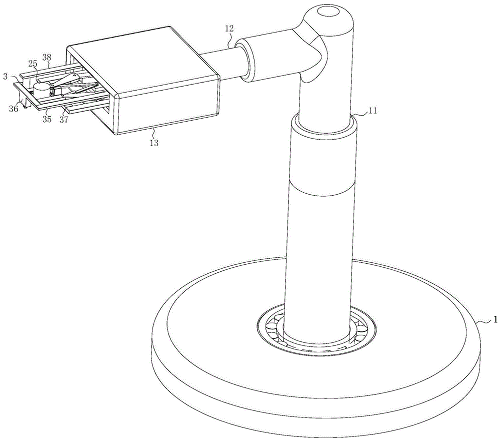
图1是本发明的立体图;Fig. 1 is the perspective view of the present invention;
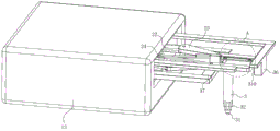
图2是本发明的剖视图;Fig. 2 is the sectional view of the present invention;
图3是本发明的运动夹紧机构的第一立体图;Fig. 3 is the first perspective view of the motion clamping mechanism of the present invention;
图4是本发明的运动夹紧机构的第二立体图;4 is a second perspective view of the motion clamping mechanism of the present invention;
图5是图4中A处的局部放大视图;Fig. 5 is the partial enlarged view of A place in Fig. 4;
图中:底座1、第一伸缩气缸11、第二伸缩气缸12、固定壳13、第一弹簧14、动力箱2、第一齿轮21、第一连杆22、第二连杆23、第三连杆24、热锻毛坯25、第二夹板26、第二弹簧27、定位销3、第一钢珠31、第二钢珠32、第二齿轮33、第三齿轮34、第一齿条35、第一限位块36、第二限位块37、第二齿条38、导向块39、第一夹板310。In the figure:
具体实施方式Detailed ways
为了使本发明实现的技术手段、创作特征、达成目的与功效易于明白了解,下面结合具体实施方式,进一步阐述本发明。In order to make it easy to understand the technical means, creation features, achieved goals and effects of the present invention, the present invention will be further described below with reference to the specific embodiments.
如图1至图5所示,本发明所述的一种可以实现工件精确定位的机器人搬运手爪,包括底座1、动力箱2和定位销3,所述底座1的上表面转动连接有转动柱;所述转动柱的上表面固连有第一伸缩气缸11;所述第一伸缩气缸11的弧形面靠近第一伸缩气缸11活塞杆的上端面位置固连有水平放置的第二伸缩气缸12;所述第二伸缩气缸12的活塞杆的端面位置固连有固定壳13;所述固定壳13的内部开设有第一空腔;所述第一空腔的内部于固定壳13的底部位置滑动连接有动力箱2;所述动力箱2的内部开设有第二空腔;所述动力箱2的上表面靠近动力箱2背离第二伸缩气缸12的一侧侧面位置开设有第一转动孔;所述第一转动孔的数量为二,且左右对称设置;两个所述第一转动孔的内部均转动连接有第一传动柱;两个所述第一传动柱的上表面均固连有第一齿轮21,两个第一齿轮21大小相等且相互之间啮合;两个所述第一传动柱的下表面于第二空腔的内部位置分别固连有第一电机和第二电机;所述第一电机和第二电机之间正反方式运转,且均与动力箱2相固连;两个所述第一传动柱的弧形面于第一齿轮21和动力箱2之间位置均固连有第一连杆22;所述动力箱2的侧面于第一连杆22位置开设有传动孔;且第一连杆22穿过传动孔均延伸至动力箱2的外部;所述第一连杆22远离动力箱2的一侧端面位置均铰接有第二连杆23;两个所述第二连杆23均为“V”形结构设计;所述动力箱2于传动孔一侧侧面中间位置固连有固定块;所述固定块的上表面铰接有两个对称设置的第三连杆24;两个所述第三连杆24分别与对应的第二连杆23之间相互铰接;两个所述第二连杆23之间位置共同夹有同一个热锻毛坯25;所述动力箱2靠近热锻毛坯25位置设有定位销3;工作时,由于齿轮需要有具有较高的硬度、耐磨性以及精度要求,因此现有技术中有通过热精锻方式进行制作齿轮,制作的过程中为了保证齿轮加工品质,因此需要将热锻毛坯25的加热装置和锻造模具置于同一真空罩内,由于真空罩内的温度较高且要求真空环境,因此无法通过人工方式进行进行热锻毛坯25的取放,故需要通过机器人手爪进行搬运,使得加热装置内的热锻毛坯25可以转运到锻造模具内,由于热精锻齿轮需要较高的定位精度以满足高效和高精度的加工需求,因此需要实现机器人手爪的高精度定位功能,当需要转运加热装置内的毛坯时,首先使得转动柱在底座1内转动,同时配合第一伸缩气缸11和第二伸缩气缸12的活塞杆顶出和内收,使得热锻毛坯25位于两个第二连杆23之间位置,然后分别正反向转动对应的第一电机和第二电机,第一电机和第二电机带动对应的第一传动柱转动,进而带动第一传动柱上方的两个第一齿轮21转动,两个第一齿轮21之间相互啮合且传动比为一,因此可以有效的带动两个第一连杆22的转动,通过第一连杆22上均铰接第二连杆23,且第二连杆23的表面均铰接第三连杆24,且两个第三连杆24的另一端均共同铰接于同一个固定块的表面,因此两个第一齿轮21通过啮合方式,实现了两个第二连杆23的同步相向或相背方向移动,且移动距离同步相等,因此在第二连杆23在夹紧热锻毛坯25时,可以保证两个第二连杆23的定位始终保持对称,进而实现更高的夹紧精度要求,通过设置定位销3,且定位销3和热精锻的模具的定位孔对应插接,且定位孔的口部为喇叭状结构,保证每次放置热锻毛坯25时,可以进行有效的定位同时可以进行小幅度调整,同时如定位销3未有效的插接于对应的定位孔内时,机器人搬运手爪会停止运转,提醒检修,通过一种可以实现工件精确定位的机器人搬运手爪,有效的解决了现有技术中,机器人手爪夹取热锻毛坯25时,不同的夹紧板之间移动精度较低,使得夹紧力度不平衡,进而导致热锻毛坯25的位置精度较低,且无定位销3的插接定位作用,一方面使得手爪无法小幅度调整,另一方面无检修反馈,容易导致产品批量性加工不良等问题,有效的适应了热锻齿轮的工艺加工需要,同时保证了热锻毛坯25高精度的定位,有效的提高了高精度热锻齿轮的良品率。As shown in FIG. 1 to FIG. 5 , a robot handling gripper that can realize precise positioning of workpieces according to the present invention includes a
作为本发明的一种实施方式,所述定位销3的下表面倒有斜角;所述定位销3的下表面滚动连接有一个第一钢珠31;所述定位销3的斜角所在的面滚动连接有均匀布置的第二钢珠32;以定位销3的轴线为中心,所述第二钢珠32所在的最大轮廓外圆直径小于定位销3的直径;工作时,当定位销3开始插接于定位孔内时,由于位置存在小的偏差,因此定位销3可以通过定位孔喇叭状的开口划入到定位孔内,但是当定位销3长时间反复插接于定位孔,定位销3的底部会和定位孔喇叭状的开口反复摩擦,一方面容易造成定位销3的划伤或断裂,另一方面也会使得定位机构运动定位过程出现摩擦异响,不利于长期高效的加工需求,因此通过在定位销3的表面设置第一钢柱和均匀布置的第二钢柱,定位销3在插接入定位孔喇叭状的开口位置时,有效的实现了定位销3和定位孔的滚动摩擦接触,减少了摩擦力,避免了接触面的划伤磨损,实现了定位的高效运转。As an embodiment of the present invention, the lower surface of the
作为本发明的一种实施方式,所述动力箱2滑动连接于固定壳13;所述第一空腔的内部于固定壳13的侧壁和动力箱2的侧壁之间位置固连有均匀布置的第一弹簧14;工作时,由于动力箱2在第一空腔内并与固定壳13滑动连接,因此在定位销3插接入定位孔实现定位之前,会出现动力箱2在固定壳13的内部前后左右窜动的现象,进而会影响第二连杆23位置定位,以及对热锻毛坯25进行快速有效的夹紧,因此通过设置在固定壳13和动力箱2之间位置固连均匀布置的第一弹簧14,通过第一弹簧14的弹力作用,可以使得固定壳13在未受到外力的条件下,基本位于第一空腔的中间位置,因此可以保证定位销3的初始位置精度,同时也可以避免动力箱2在第一空腔的内部窜动,造成动力箱2和固定壳13的侧壁之间产生碰撞,影响运动机构的稳定性以及机器人搬运手爪的使用寿命。As an embodiment of the present invention, the power box 2 is slidably connected to the fixed
作为本发明的一种实施方式,所述动力箱2的上表面靠近第二伸缩杆位置开设有两个第二转动孔;两个所述第二转动孔的内部均转动连接有第二传动柱;两个所述第二传动柱的上表面分别固连有第二齿轮33和第三齿轮34;所述第二齿轮33和第三齿轮34之间相互啮合,且第二齿轮33和第三齿轮34的传动比为二;两个所述第二传动柱的下表面于第二空腔的内部位置分别固连有第三电机和第四电机,且第三电机与第二齿轮33均位于同一个第二传动柱表面;所述第三电机和第四电机之间正反方式运转,且均与动力箱2相固连;所述第二齿轮33啮合连接有第一齿条35;所述第一齿条35于热锻毛坯25的左侧位置固连有第一限位块36;所述固定箱相对于热锻毛坯25一侧侧面固连有对称设置的支架;两个所述支架靠近热锻毛坯25位置固连有第二限位块37;所述第三齿轮34啮合连接有第二齿条38;所述第二齿条38于第一限位块36和第二限位块37之间位置固连有定位销3;所述动力箱2的上表面于第一齿条35和第二齿条38位置均固连有两个导向块39;所述第一齿轮21和第二齿轮33均滑动连接于对应的导向块39内;工作时,由于热锻毛坯25的形状不圆整或第二连杆23夹紧热锻毛坯25定位有一定偏差时,会使得热锻毛坯25的轴线和定位销3的相对基准点存在较大的偏差,因此通过第三电机和第四电机带动第二齿轮33和第三齿轮34正反向转动,第二齿轮33和第三齿轮34进而带动第一齿条35和第二齿条38在导向块39的内部滑动,通过在第一齿条35的端部位置固连第一限位块36,因此可以通过第一齿条35带动第一限位块36的运动,配合固定的第二限位块37,可以实现了热锻毛坯25前后左右四个方向的固定,通过第二齿条38于第一限位块36和第二限位块37之间位置固连有定位销3,因此滑动的第二齿条38可以带动定位销3的位置调整,同时由于第二齿轮33和第三齿轮34的传动比为二,因此可以使得第一齿条35的移动距离始终是第二齿条38移动距离的两倍,保证了定位销3始终位于第一限位块36和第二限位块37的中间位置,保证了热锻毛坯25和定位销3相对位置的固定,因此可以满足不同大小热锻毛坯25进一步有效夹紧的同时也保证了定位销3的定位精度,结构简单,自动化程度高。As an embodiment of the present invention, two second rotation holes are opened on the upper surface of the power box 2 near the second telescopic rod; the interiors of the two second rotation holes are rotatably connected with a second transmission column ; The upper surfaces of the two second transmission columns are respectively fixed with a second gear 33 and a third gear 34; the second gear 33 and the third gear 34 mesh with each other, and the second gear 33 and the third gear 34 The gear ratio of the gear 34 is two; the lower surfaces of the two second transmission columns are respectively fixed with a third motor and a fourth motor at the inner position of the second cavity, and the third motor and the second gear 33 are both located in The surface of the same second transmission column; the third motor and the fourth motor run in a forward and reverse manner, and they are both fixedly connected with the power box 2; the second gear 33 is meshed with a first rack 35; The first rack 35 is fixed with a first limit block 36 at the left position of the hot forging blank 25; the fixing box is fixed with a symmetrically arranged bracket relative to one side of the hot forging blank 25; A second limit block 37 is fixedly connected to the bracket near the hot forging blank 25 ; the third gear 34 is engaged with a second rack 38 ; the second rack 38 is connected to the first limit block 36 and the second limit Positioning pins 3 are fixedly connected between the position blocks 37; two guide blocks 39 are fixedly connected to the upper surface of the power box 2 at the positions of the first rack 35 and the second rack 38; the first gear 21 and the second gear 33 are both slidably connected in the corresponding guide blocks 39; during operation, due to the unrounded shape of the hot forging blank 25 or the positioning of the second connecting rod 23 clamping the hot forging blank 25 to a certain extent, the hot forging blank 25 will be heated. There is a large deviation between the axis of the forging blank 25 and the relative reference point of the
作为本发明的一种实施方式,所述第一限位块36、第二限位块37和两个第二连杆23之间共同连接有同一个热锻毛坯25;所述第一限位块36和第二限位块37相对于热锻毛坯25的一侧侧面位置均固连有第一夹板310,且第一夹板310均为耐高温材料设计;两个所述第二连杆23相对于热锻毛坯25的一侧侧面位置均开设有滑槽;所述滑槽的内部均滑动连接有第二夹板26,且第二夹板26均为耐高温材料设计;工作时,当需要对热锻毛坯25夹紧时,首先通过第二连杆23的转动实现对毛坯的预夹紧,然后通过移动第一限位块36使得推动热锻毛坯25贴于第二限位块37表面,进而与第二限位块37之间实现对热锻毛坯25的二次限位夹紧,但是由于第一限位块36在推动热锻毛坯25的过程中,会使得热锻毛坯25在第二连杆23的表面滑动此一方面摩擦力的作用会增加第一限位块36的运动阻力,另一方面滑动过程中也会造成毛坯和第二连杆23的损伤,影响加工精度和机器人搬运手爪的使用寿命,且第一限位块36、第二限位块37和第二连杆23直接与高温的热锻毛坯25长期反复接触也会不利于运动机构长时间的使用,因此通过在第一限位块36和第二限位块37相对的于热锻毛坯25的一侧侧面固连第一夹板310,通过将第一夹板310设计为耐高温和导热性较差的材料,可以有效的减少高温对第一限位块36和第二限位块37的影响,通过在第二连杆23的表面开设滑槽,且滑槽的内部滑动连接第二夹板26,当第一限位块36通过第一夹板310推动热锻毛坯25移动时,可以直接通过第二夹板26在滑槽的内部滑动,实现热锻毛坯25的快速无摩擦损伤的移动,且同样第二限位块37也可以设计为耐高温和导热性较差的材料,保证了运动机构的长期有效运转。As an embodiment of the present invention, the
作为本发明的一种实施方式,所述第二夹板26与对应的滑槽之间位置均固连有两个第二弹簧27,且第二弹簧27均分别位于滑槽的左右两侧侧面位置;所述第一夹板310和第二夹板26相对于热锻毛坯25一侧侧面位置均为糙面设计;工作时,当将热锻毛坯25置于热锻模具内后,由于第二夹板26均滑动到滑槽的一端位置,故会影响第二夹板26的二次滑动使用时,因此通过在第二夹板26和对应的滑槽之间位置固连第二弹簧27,且第二弹簧27左右对称设置,因此可以有效的实现第二夹板26的制动复位,且复位至滑槽的中间位置,保证了可持续工作的能力,且通过将第一夹板310和第二夹板26相对于热锻毛坯25一侧侧面位置均设计为糙面结构,可以避免热锻毛坯25的上下滑动,同时也可以保证第一夹板310在推动热锻毛坯25的时候,热锻毛坯25不会在两个第二夹板26表面滑动,保证了热锻毛坯25质量稳定性。As an embodiment of the present invention, two
具体工作流程如下:The specific workflow is as follows:
工作时,由于齿轮需要有具有较高的硬度、耐磨性以及精度要求,因此现有技术中有通过热精锻方式进行制作齿轮,制作的过程中为了保证齿轮加工品质,因此需要将热锻毛坯25的加热装置和锻造模具置于同一真空罩内,由于真空罩内的温度较高且要求真空环境,因此无法通过人工方式进行进行热锻毛坯25的取放,故需要通过机器人手爪进行搬运,使得加热装置内的热锻毛坯25可以转运到锻造模具内,由于热精锻齿轮需要较高的定位精度以满足高效和高精度的加工需求,因此需要实现机器人手爪的高精度定位功能,当需要转运加热装置内的毛坯时,首先使得转动柱在底座1内转动,同时配合第一伸缩气缸11和第二伸缩气缸12的活塞杆顶出和内收,使得热锻毛坯25位于两个第二连杆23之间位置,然后分别正反向转动对应的第一电机和第二电机,第一电机和第二电机带动对应的第一传动柱转动,进而带动第一传动柱上方的两个第一齿轮21转动,两个第一齿轮21之间相互啮合且传动比为一,因此可以有效的带动两个第一连杆22的转动,通过第一连杆22上均铰接第二连杆23,且第二连杆23的表面均铰接第三连杆24,且两个第三连杆24的另一端均共同铰接于同一个固定块的表面,因此两个第一齿轮21通过啮合方式,实现了两个第二连杆23的同步相向或相背方向移动,且移动距离同步相等,因此在第二连杆23在夹紧热锻毛坯25时,可以保证两个第二连杆23的定位始终保持对称,进而实现更高的夹紧精度要求,通过设置定位销3,且定位销3和热精锻的模具的定位孔对应插接,且定位孔的口部为喇叭状结构,保证每次放置热锻毛坯25时,可以进行有效的定位同时可以进行小幅度调整,同时如定位销3未有效的插接于对应的定位孔内时,机器人搬运手爪会停止运转,提醒检修;通过在定位销3的表面设置第一钢柱和均匀布置的第二钢柱,定位销3在插接入定位孔喇叭状的开口位置时,有效的实现了定位销3和定位孔的滚动摩擦接触,减少了摩擦力,避免了接触面的划伤磨损;通过设置在固定壳13和动力箱2之间位置固连均匀布置的第一弹簧14,通过第一弹簧14的弹力作用,可以使得固定壳13在未受到外力的条件下,基本位于第一空腔的中间位置,因此可以保证定位销3的初始位置精度,同时也可以避免动力箱2在第一空腔的内部窜动;通过第三电机和第四电机带动第二齿轮33和第三齿轮34正反向转动,第二齿轮33和第三齿轮34进而带动第一齿条35和第二齿条38在导向块39的内部滑动,通过在第一齿条35的端部位置固连第一限位块36,因此可以通过第一齿条35带动第一限位块36的运动,配合固定的第二限位块37,可以实现了热锻毛坯25前后左右四个方向的固定,通过第二齿条38于第一限位块36和第二限位块37之间位置固连有定位销3,因此滑动的第二齿条38可以带动定位销3的位置调整,同时由于第二齿轮33和第三齿轮34的传动比为二,因此可以使得第一齿条35的移动距离始终是第二齿条38移动距离的两倍,保证了定位销3始终位于第一限位块36和第二限位块37的中间位置,保证了热锻毛坯25和定位销3相对位置的固定;通过在第一限位块36和第二限位块37相对的于热锻毛坯25的一侧侧面固连第一夹板310,通过将第一夹板310设计为耐高温和导热性较差的材料,可以有效的减少高温对第一限位块36和第二限位块37的影响,通过在第二连杆23的表面开设滑槽,且滑槽的内部滑动连接第二夹板26,当第一限位块36通过第一夹板310推动热锻毛坯25移动时,可以直接通过第二夹板26在滑槽的内部滑动,实现热锻毛坯25的快速无摩擦损伤的移动,且同样第二限位块37也可以设计为耐高温和导热性较差的材料,保证了运动机构的长期有效运转;通过在第二夹板26和对应的滑槽之间位置固连第二弹簧27,且第二弹簧27左右对称设置,因此可以有效的实现第二夹板26的制动复位,且复位至滑槽的中间位置,保证了可持续工作的能力,且通过将第一夹板310和第二夹板26相对于热锻毛坯25一侧侧面位置均设计为糙面结构,可以避免热锻毛坯25的上下滑动,同时也可以保证第一夹板310在推动热锻毛坯25的时候,热锻毛坯25不会在两个第二夹板26表面滑动。During operation, since the gears need to have high hardness, wear resistance and precision requirements, the gears are manufactured by hot precision forging in the prior art. The heating device of the blank 25 and the forging die are placed in the same vacuum hood. Due to the high temperature in the vacuum hood and the requirement of a vacuum environment, the hot forging blank 25 cannot be picked and placed manually, so it needs to be carried out by a robot gripper. Handling, so that the hot forging blank 25 in the heating device can be transferred to the forging die. Since the hot precision forging gear needs high positioning accuracy to meet the high-efficiency and high-precision processing requirements, it is necessary to realize the high-precision positioning function of the robot gripper. , when it is necessary to transfer the blank in the heating device, first make the rotating column rotate in the
以上显示和描述了本发明的基本原理、主要特征和优点,本行业的技术人员应该了解,本发明不受上述实施例的限制,上述实施例和说明书中描述的只是说明本发明的原理,在不脱离本发明精神和范围的前提下,本发明还会有各种变化和改进,这些变化和改进都落入要求保护的本发明范围内,本发明要求保护范围由所附的权利要求书及其等效物界定。The basic principles, main features and advantages of the present invention are shown and described above. Those skilled in the art should understand that the present invention is not limited by the above-mentioned embodiments. The above-mentioned embodiments and descriptions only illustrate the principles of the present invention. Under the premise of not departing from the spirit and scope of the present invention, the present invention will also have various changes and improvements, and these changes and improvements all fall within the scope of the claimed invention, and the claimed scope of the present invention is determined by the appended claims and Its equivalents are defined.
Claims (3)
Priority Applications (1)
| Application Number | Priority Date | Filing Date | Title |
|---|---|---|---|
| CN201911393544.8A CN111015640B (en) | 2019-12-30 | 2019-12-30 | A Robot Handling Gripper That Can Realize Precise Positioning of Workpieces |
Applications Claiming Priority (1)
| Application Number | Priority Date | Filing Date | Title |
|---|---|---|---|
| CN201911393544.8A CN111015640B (en) | 2019-12-30 | 2019-12-30 | A Robot Handling Gripper That Can Realize Precise Positioning of Workpieces |
Publications (2)
| Publication Number | Publication Date |
|---|---|
| CN111015640A CN111015640A (en) | 2020-04-17 |
| CN111015640B true CN111015640B (en) | 2020-12-29 |
Family
ID=70195943
Family Applications (1)
| Application Number | Title | Priority Date | Filing Date |
|---|---|---|---|
| CN201911393544.8A Expired - Fee Related CN111015640B (en) | 2019-12-30 | 2019-12-30 | A Robot Handling Gripper That Can Realize Precise Positioning of Workpieces |
Country Status (1)
| Country | Link |
|---|---|
| CN (1) | CN111015640B (en) |
Families Citing this family (2)
| Publication number | Priority date | Publication date | Assignee | Title |
|---|---|---|---|---|
| CN114633271B (en) * | 2022-03-10 | 2024-04-16 | 常州大学 | A flexible gripping manipulator with self-locking gears |
| CN116551565A (en) * | 2023-05-24 | 2023-08-08 | 芜湖信友机械制造有限公司 | A gate valve sealing surface processing device |
Family Cites Families (7)
| Publication number | Priority date | Publication date | Assignee | Title |
|---|---|---|---|---|
| JP2012236265A (en) * | 2011-05-13 | 2012-12-06 | Seiko Epson Corp | Robot hand, and robot |
| CN103612202B (en) * | 2013-11-19 | 2016-01-20 | 中国科学院光电技术研究所 | Positioning device for workpiece fixture in ion beam polishing equipment |
| CN107825410A (en) * | 2017-12-01 | 2018-03-23 | 四川巨海渔业科技有限公司 | A kind of clamp device with turn over function |
| CN108621120A (en) * | 2018-07-09 | 2018-10-09 | 薛敏强 | A kind of conveying machinery arm of Multifunctional rotary displacement that capableing of branch's feeding |
| CN109048418B (en) * | 2018-09-03 | 2023-05-23 | 上海莘翔自动化科技有限公司 | Four-side clamping mechanism and operation method |
| CN110394787A (en) * | 2019-03-06 | 2019-11-01 | 沈阳工业大学 | A bearing ring billet handling manipulator |
| CN110405745A (en) * | 2019-07-29 | 2019-11-05 | 南京蹑波物联网科技有限公司 | A kind of clamping header structure for industrial robot |
-
2019
- 2019-12-30 CN CN201911393544.8A patent/CN111015640B/en not_active Expired - Fee Related
Also Published As
| Publication number | Publication date |
|---|---|
| CN111015640A (en) | 2020-04-17 |
Similar Documents
| Publication | Publication Date | Title |
|---|---|---|
| CN205870522U (en) | A five-axis swing arm forging robot | |
| CN107116801B (en) | Automatic welding machine for cross-flow fan blades | |
| CN214686616U (en) | A positioning mechanism for machining mechanical parts | |
| CN206445585U (en) | A Universal Automatic Unloading Mechanism for CNC Machine Tool | |
| CN109384379B (en) | Workpiece transfer mechanism, workpiece transfer method and glass hot-bending forming equipment | |
| CN111300125A (en) | A lock cylinder transmission clamping arm | |
| CN111015640A (en) | Robot carrying paw capable of realizing accurate positioning of workpiece | |
| CN219786154U (en) | Full-automatic elbow processing equipment | |
| CN109773560B (en) | Automatic feeding and discharging device for double-station vice milling and feeding and discharging method | |
| CN115302329B (en) | A processing production line for shaft parts | |
| CN215973863U (en) | Cylindrical ceramic carrier clamping jaw | |
| CN116765305B (en) | Conveying device for gear forging | |
| CN106735320A (en) | Pipe axle ultraprecise automates Special Purpose Machine for Processing | |
| CN212398541U (en) | Rear-mounted pneumatic double-acting chuck mechanism | |
| CN209957836U (en) | Machine tool for laser quenching of die | |
| CN209206629U (en) | The dedicated chuck of high speed gear hobber | |
| CN212197481U (en) | a transport device | |
| CN215511102U (en) | Centering manipulator | |
| CN117245217A (en) | Robot welding device with automatic error compensation function | |
| CN224116175U (en) | Quick positioning fixture device for industrial robot | |
| CN115007758A (en) | An automatic shrinking device | |
| CN115582849A (en) | A variable position robot end effector | |
| CN115351425A (en) | Automatic welding production line | |
| CN209850950U (en) | Adjustable connecting rod type grabbing manipulator | |
| CN222359151U (en) | A sheet material rapid positioning structure |
Legal Events
| Date | Code | Title | Description |
|---|---|---|---|
| PB01 | Publication | ||
| PB01 | Publication | ||
| SE01 | Entry into force of request for substantive examination | ||
| SE01 | Entry into force of request for substantive examination | ||
| GR01 | Patent grant | ||
| GR01 | Patent grant | ||
| CF01 | Termination of patent right due to non-payment of annual fee |
Granted publication date: 20201229 |
|
| CF01 | Termination of patent right due to non-payment of annual fee |