CN110996602B - Installation main frame of server cabinet and installation method thereof - Google Patents
Installation main frame of server cabinet and installation method thereof Download PDFInfo
- Publication number
- CN110996602B CN110996602B CN201911329189.8A CN201911329189A CN110996602B CN 110996602 B CN110996602 B CN 110996602B CN 201911329189 A CN201911329189 A CN 201911329189A CN 110996602 B CN110996602 B CN 110996602B
- Authority
- CN
- China
- Prior art keywords
- server
- placing
- server cabinet
- groove
- cabinet
- Prior art date
- Legal status (The legal status is an assumption and is not a legal conclusion. Google has not performed a legal analysis and makes no representation as to the accuracy of the status listed.)
- Active
Links
Images


Classifications
-
- H—ELECTRICITY
- H05—ELECTRIC TECHNIQUES NOT OTHERWISE PROVIDED FOR
- H05K—PRINTED CIRCUITS; CASINGS OR CONSTRUCTIONAL DETAILS OF ELECTRIC APPARATUS; MANUFACTURE OF ASSEMBLAGES OF ELECTRICAL COMPONENTS
- H05K7/00—Constructional details common to different types of electric apparatus
- H05K7/14—Mounting supporting structure in casing or on frame or rack
- H05K7/1485—Servers; Data center rooms, e.g. 19-inch computer racks
- H05K7/1488—Cabinets therefor, e.g. chassis or racks or mechanical interfaces between blades and support structures
Abstract
The invention discloses an installation main frame of a server cabinet and an installation method thereof, relates to the technical field of installation main frames of server cabinets and installation methods thereof, and aims to solve the problem that when an existing server cabinet is used for placing a server, the server is damaged and cannot be normally used due to overlarge impact force generated during placing. The utility model discloses a server cabinet, including server rack, sealing strip, closing plate, spring standing groove, the outside of server rack one end is provided with the sealing strip, and the sealing strip is provided with four, the one end of server rack is provided with the backup pad draw-in groove, and the backup pad draw-in groove with be provided with ten, the inner wall of server rack is provided with the light, and the light is provided with a plurality of, the inside one side of server rack is provided with the closing plate, and the closing plate passes through the draw-in groove with the server rack and be connected, the inside.
Description
Technical Field
The invention relates to the technical field of installation main frames of server cabinets and installation methods thereof, in particular to an installation main frame of a server cabinet and an installation method thereof.
Background
With the rapid development of economy in China and the continuous progress of the science and technology level in China, the most used equipment on the Internet is the server, a server cabinet is used when the server is placed, the server cabinet is used for combining and installing a panel, a plug-in box, an electronic element, a device, mechanical parts and components to form an integral installation box, the server cabinet consists of a frame and a cover plate (door), generally has a cuboid shape and is placed on the ground, and the server cabinet provides adaptive environment and safety protection for the normal work of electronic equipment.
The existing server cabinet is often damaged and cannot be normally used due to the fact that too large collision force is generated when the existing server cabinet is used for placing the servers, and in order to solve the problem, the installation main frame of the server cabinet and the installation method of the installation main frame are designed to place the servers very importantly.
Disclosure of Invention
The invention aims to provide an installation main frame of a server cabinet and an installation method thereof, which aim to solve the problem that when the existing server cabinet is used for placing a server, the server is often damaged and cannot be normally used due to overlarge impact force generated during placing.
In order to achieve the purpose, the invention provides the following technical scheme: an installation main frame of a server cabinet comprises the server cabinet, wherein the outer part of one end of the server cabinet is provided with four sealing strips, one end of the server cabinet is provided with support plate clamping grooves, the number of the support plate clamping grooves is ten, the inner wall of the server cabinet is provided with a plurality of illuminating lamps, one side of the inner part of the server cabinet is provided with a sealing plate, the sealing plate is connected with the server cabinet through the clamping grooves, an active carbon placing box is arranged below the inner part of the server cabinet, spring placing grooves are arranged inside the active carbon placing box, the number of the spring placing grooves is eight, buffer springs are arranged inside the spring placing grooves, a server placing plate is arranged above the buffer springs and is connected with the buffer springs through the clamping grooves, the lower end of the inner part of the server cabinet is provided with a photoelectric sensor placing groove, the photoelectric sensor placing groove is internally provided with a photoelectric sensor, the photoelectric sensor and the photoelectric sensor placing groove are fixedly connected through a photoelectric sensor limiting block, two ends above the server cabinet are respectively provided with a scratching groove, a fixed top plate is arranged at the middle position of the two scratching grooves, four corners of the fixed top plate are respectively provided with a fixed connecting block, the fixed connecting blocks are connected with the server cabinet through bolts, a dustproof filter screen is arranged above the fixed top plate and is connected with the fixed top plate through a clamping groove, the photoelectric sensor is connected with a lighting lamp through an electric conductor, one end of the outside of the server cabinet is provided with a supporting plate placing block, the inside of the supporting plate clamping groove is provided with a supporting plate, the other end of the outside of the server cabinet is provided with an L limiting block, the inside of the L limiting block is provided with a cabinet door, four corners of the cabinet door are provided with fixing lugs, the outside of the active carbon placing box is provided with a plurality of circulation holes, and the circulation holes are provided with a plurality of circulation holes.
Preferably, the width of the supporting plate clamping groove is larger than that of the movable supporting plate.
Preferably, the size of the two digging grooves is larger than that of the fixed top plate.
Preferably, the outer diameter of the buffer spring is 90MM, and the diameter of the spring placing groove is 95 MM.
Preferably, the method for manufacturing the installation main frame of the server cabinet comprises the following steps:
s1: placing the server cabinet to a position to be used, and connecting the sealing plate with the server cabinet through a bolt, wherein the size of the bolt is M3.5;
s2: then taking out the active carbon placing box, placing the active carbon placing box below the inside of the server cabinet, taking out the buffer spring with the size of 90MM and placing the buffer spring into the spring placing groove with the diameter of 95MM, taking out the server placing plate and placing the server placing plate on the buffer spring, wherein the server placing plate is connected with the buffer spring through a clamping groove;
s3: at the moment, the fixed top plate can be taken out, the fixed top plate is placed in the digging groove, then the dustproof filter screen is clamped on the fixed top plate, and the fixed connecting block and the fixed top plate are fixed through a bolt with the size of M3.5;
s4: then can take out movable backup pad according to the needs of oneself, with the both ends of movable backup pad place the inside of backup pad draw-in groove can.
Compared with the prior art, the invention has the beneficial effects that: according to the invention, the buffer spring is arranged when the server is placed by the worker, the design of the buffer spring can greatly reduce the collision force between the server and the server cabinet, the design of the active carbon placing box can absorb more moisture in the air, the short circuit of the internal circuit of the server due to excessive moisture can not be caused, the service life of the server is prolonged, the problem that the internal elements of the server can not be normally damaged due to the reduction of the collision force between the server and the server cabinet when the worker places the server is solved, the maintenance frequency and the replacement frequency of the server can be reduced, and the economic loss is greatly reduced.
Drawings
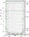
FIG. 1 is a schematic view of the overall structure of the present invention;
FIG. 2 is an enlarged view of a portion of the area A of the present invention;
FIG. 3 is a top plan view of the overall structure of the present invention;
FIG. 4 is a top view of the activated carbon placing case of the present invention.
In the figure: 1. a server cabinet; 2. a sealing strip; 3. fixing the groove; 4. a support plate placing block; 5. a clamping groove of the supporting plate; 6. an illuminating lamp; 7. a movable support plate; 8. a spring placing groove; 9. a sealing plate; 10. fixing a top plate; 11. fixing the bump; 12. a cabinet door; 13. a vent hole; 14. a server placement board; 15. a buffer spring; 16. an L-shaped limiting block; 17. a dustproof filter screen; 18. an active carbon placing box; 19. a flow-through hole; 20. a photoelectric sensor placement groove; 21. a photoelectric sensor limiting block; 22. a photosensor; 23. digging a groove; 24. and fixing the connecting block.
Detailed Description
The technical solutions in the embodiments of the present invention will be clearly and completely described below with reference to the drawings in the embodiments of the present invention, and it is obvious that the described embodiments are only a part of the embodiments of the present invention, and not all of the embodiments.
Referring to fig. 1-4, an embodiment of the present invention is shown: an installation main frame of a server cabinet comprises a server cabinet 1, wherein the outer part of one end of the server cabinet 1 is provided with four sealing strips 2, the number of the sealing strips 2 is four, one end of the server cabinet 1 is provided with a support plate clamping groove 5, the number of the support plate clamping grooves 5 is ten, the inner wall of the server cabinet 1 is provided with a plurality of illuminating lamps 6, one side of the inner part of the server cabinet 1 is provided with a sealing plate 9, the sealing plate 9 is connected with the server cabinet 1 through the clamping grooves, the lower part of the inner part of the server cabinet 1 is provided with an active carbon placing box 18, the inner part of the active carbon placing box 18 is provided with a spring placing groove 8, the number of the spring placing grooves 8 is eight, the inner part of the spring placing groove 8 is provided with a buffer spring 15, the upper part of the buffer spring 15 is provided with a, a photoelectric sensor placing groove 20 is arranged at the lower end inside a server cabinet 1, a photoelectric sensor 22 is arranged inside the photoelectric sensor placing groove 20, the photoelectric sensor 22 and the photoelectric sensor placing groove 20 are fixedly connected through a photoelectric sensor limiting block 21, two ends above the server cabinet 1 are respectively provided with a scratching groove 23, a fixed top plate 10 is arranged at the middle position of the two scratching grooves 23, four corners of the fixed top plate 10 are respectively provided with a fixed connecting block 24, the fixed connecting blocks 24 are connected with the server cabinet 1 through bolts, a dustproof filter screen 17 is arranged above the fixed top plate 10, the dustproof filter screen 17 is connected with the fixed top plate 10 through clamping grooves, the photoelectric sensor 22 is connected with an illuminating lamp 6 through an electric conductor, a support plate placing block 4 is arranged at one end outside the server cabinet 1, and a movable support plate 7 is arranged inside a support plate clamping groove 5, the other end of server rack 1 outside is provided with L stopper 16, and the inside of L stopper 16 is provided with cabinet door 12, and four corners of cabinet door 12 all are provided with fixed lug 11, and the outside that box 18 was placed to the active carbon is provided with opening 19, and opening 19 is provided with a plurality of.
Further, the width of the support plate clamping groove 5 is larger than that of the movable support plate 7.
Further, the size of the two digging grooves 23 is larger than that of the fixed top plate 10.
Further, the manufacturing method of the installation main frame of the server cabinet, wherein the outer diameter of the buffer spring 15 is 90MM, and the diameter of the spring placing groove 8 is 95MM, comprises the following steps:
s1: the server cabinet 1 is placed at a position to be used, and then the sealing plate 9 is connected with the server cabinet 1 through bolts, wherein the size of each bolt is M3.5;
s2: then taking out the activated carbon placing box 18, placing the activated carbon placing box 18 below the inside of the server cabinet 1, taking out the buffer spring 15 with the size of 90MM and placing the buffer spring 15 into the spring placing groove 8 with the diameter of 95MM, then taking out the server placing plate 14 and placing the server placing plate on the buffer spring 15, wherein the server placing plate 14 is connected with the buffer spring 15 through a clamping groove;
s3: at this time, the fixed top plate 10 can be taken out, the fixed top plate 10 is placed inside the digging groove 23, then the dustproof filter screen 17 is clamped on the fixed top plate 10, and the fixed connecting block 24 and the fixed top plate are fixed through a bolt with the size of M3.5;
s4: then can take out movable backup pad 7 according to own needs, can place the inside of backup pad draw-in groove with the both ends of movable backup pad 7 can.
It will be evident to those skilled in the art that the invention is not limited to the details of the foregoing illustrative embodiments, and that the present invention may be embodied in other specific forms without departing from the spirit or essential attributes thereof. The present embodiments are therefore to be considered in all respects as illustrative and not restrictive, the scope of the invention being indicated by the appended claims rather than by the foregoing description, and all changes which come within the meaning and range of equivalency of the claims are therefore intended to be embraced therein. Any reference sign in a claim should not be construed as limiting the claim concerned.
Claims (5)
1. The utility model provides an installation body frame of server rack, includes server rack (1), its characterized in that: the outer portion of one end of the server cabinet (1) is provided with four sealing strips (2), one end of the server cabinet (1) is provided with support plate clamping grooves (5), the support plate clamping grooves (5) are ten, the inner wall of the server cabinet (1) is provided with illuminating lamps (6), the illuminating lamps (6) are provided with a plurality of sealing plates (9), one side of the inner portion of the server cabinet (1) is provided with a sealing plate (9), the sealing plate (9) is connected with the server cabinet (1) through the clamping grooves, the lower portion of the inner portion of the server cabinet (1) is provided with an active carbon placing box (18), the inner portion of the active carbon placing box (18) is provided with a spring placing groove (8), the spring placing groove (8) is provided with eight, the inner portion of the spring placing groove (8) is provided with a buffer spring (15), the upper portion of the buffer spring (15) is provided with a, and the server placing plate (14) is connected with the buffer spring (15) through a clamping groove, the lower end inside the server cabinet (1) is provided with a photoelectric sensor placing groove (20), the photoelectric sensor (22) is arranged inside the photoelectric sensor placing groove (20), the photoelectric sensor (22) is fixedly connected with the photoelectric sensor placing groove (20) through a photoelectric sensor limiting block (21), both ends above the server cabinet (1) are provided with digging grooves (23), the middle positions of the two digging grooves (23) are provided with fixed top plates (10), four corners of the fixed top plates (10) are provided with fixed connecting blocks (24), the fixed connecting blocks (24) are connected with the server cabinet (1) through bolts, a dustproof filter screen (17) is arranged above the fixed top plates (10), and the dustproof filter screen (17) is connected with the fixed top plates (10) through the clamping groove, photoelectric sensor (22) are connected through the electric conductor with light (6), the outside one end of server rack (1) is provided with the backup pad and places piece (4), the inside of backup pad draw-in groove (5) is provided with mobile backup pad (7), the outside other end of server rack (1) is provided with L stopper (16), the inside of L stopper (16) is provided with cabinet door (12), four corners of cabinet door (12) all are provided with fixed lug (11), the outside that box (18) was placed to active carbon is provided with opening (19), and opening (19) are provided with a plurality of.
2. A mounting frame for a server rack as claimed in claim 1, wherein: the width of the supporting plate clamping groove (5) is larger than that of the movable supporting plate (7).
3. A mounting frame for a server rack as claimed in claim 1, wherein: the size of the two digging grooves (23) is larger than that of the fixed top plate (10).
4. A mounting frame for a server rack as claimed in claim 1, wherein: the outer diameter of the buffer spring (15) is 90MM, and the diameter of the spring placing groove (8) is 95 MM.
5. A mounting frame for a server cabinet according to claim 1, wherein the method of manufacturing the mounting frame for a server cabinet comprises the steps of:
s1: the server cabinet (1) is placed at a position needing to be used, and then the sealing plate (9) is connected with the server cabinet (1) through bolts, wherein the size of each bolt is M3.5;
s2: then taking out the activated carbon placing box (18), placing the activated carbon placing box (18) below the inside of the server cabinet (1), taking out the buffer spring (15) with the size of 90MM and placing the buffer spring (15) into the spring placing groove (8) with the diameter of 95MM, taking out the server placing plate (14) and placing the server placing plate on the buffer spring (15), wherein the server placing plate (14) is connected with the buffer spring (15) through a clamping groove;
s3: taking out the fixed top plate (10), placing the fixed top plate (10) into the digging groove (23), then clamping the dustproof filter screen (17) on the fixed top plate (10), and fixing the fixed connecting block (24) and the fixed top plate through a bolt with the size of M3.5;
s4: then take out movable backup pad (7) as required, with the both ends of movable backup pad (7) place the inside of backup pad draw-in groove can.
Priority Applications (1)
| Application Number | Priority Date | Filing Date | Title |
|---|---|---|---|
| CN201911329189.8A CN110996602B (en) | 2019-12-20 | 2019-12-20 | Installation main frame of server cabinet and installation method thereof |
Applications Claiming Priority (1)
| Application Number | Priority Date | Filing Date | Title |
|---|---|---|---|
| CN201911329189.8A CN110996602B (en) | 2019-12-20 | 2019-12-20 | Installation main frame of server cabinet and installation method thereof |
Publications (2)
| Publication Number | Publication Date |
|---|---|
| CN110996602A CN110996602A (en) | 2020-04-10 |
| CN110996602B true CN110996602B (en) | 2021-01-12 |
Family
ID=70074406
Family Applications (1)
| Application Number | Title | Priority Date | Filing Date |
|---|---|---|---|
| CN201911329189.8A Active CN110996602B (en) | 2019-12-20 | 2019-12-20 | Installation main frame of server cabinet and installation method thereof |
Country Status (1)
| Country | Link |
|---|---|
| CN (1) | CN110996602B (en) |
Citations (9)
| Publication number | Priority date | Publication date | Assignee | Title |
|---|---|---|---|---|
| CN205667041U (en) * | 2016-06-03 | 2016-10-26 | 郑州市佳霖科技有限公司 | Modular high -tension electricity cabinet |
| CN206226894U (en) * | 2016-11-16 | 2017-06-06 | 广州市康汇电子科技有限公司 | A kind of server cabinet |
| CN107359531A (en) * | 2017-09-16 | 2017-11-17 | 范雨鸽 | A kind of dehumidification system |
| CN107396566A (en) * | 2017-08-16 | 2017-11-24 | 浙江耀耀科技有限公司 | A kind of electronics protection casing with heat sinking function |
| CN206697785U (en) * | 2017-04-28 | 2017-12-01 | 国家电网公司 | Transformer station outdoor terminal box with chamber door detection |
| CN206962303U (en) * | 2017-07-20 | 2018-02-02 | 国网山东省电力公司广饶县供电公司 | Floor type high voltage prepayment metering cabinet with shock-absorbing function |
| CN208489562U (en) * | 2018-05-27 | 2019-02-12 | 汪永祥 | A kind of box-type transformer cabinet door monitoring device with temp monitoring function |
| CN208963595U (en) * | 2018-10-21 | 2019-06-11 | 天津天辰物流股份有限公司 | A kind of box for material circulation with classification storage |
| CN209806205U (en) * | 2018-11-30 | 2019-12-17 | 吉林省芝麻软件开发中心 | Dustproof dampproofing computer cabinet |
Family Cites Families (3)
| Publication number | Priority date | Publication date | Assignee | Title |
|---|---|---|---|---|
| CN206332351U (en) * | 2017-01-03 | 2017-07-14 | 珠海立潮电力科技有限公司 | A kind of electric power distributing cabinet with noise reduction function |
| CN207853260U (en) * | 2017-12-21 | 2018-09-11 | 丁青全 | A kind of dust-protection type distribution box |
| CN209546149U (en) * | 2018-12-23 | 2019-10-25 | 辽宁工业大学 | A kind of electric machine controller with shock-absorbing function |
-
2019
- 2019-12-20 CN CN201911329189.8A patent/CN110996602B/en active Active
Patent Citations (9)
| Publication number | Priority date | Publication date | Assignee | Title |
|---|---|---|---|---|
| CN205667041U (en) * | 2016-06-03 | 2016-10-26 | 郑州市佳霖科技有限公司 | Modular high -tension electricity cabinet |
| CN206226894U (en) * | 2016-11-16 | 2017-06-06 | 广州市康汇电子科技有限公司 | A kind of server cabinet |
| CN206697785U (en) * | 2017-04-28 | 2017-12-01 | 国家电网公司 | Transformer station outdoor terminal box with chamber door detection |
| CN206962303U (en) * | 2017-07-20 | 2018-02-02 | 国网山东省电力公司广饶县供电公司 | Floor type high voltage prepayment metering cabinet with shock-absorbing function |
| CN107396566A (en) * | 2017-08-16 | 2017-11-24 | 浙江耀耀科技有限公司 | A kind of electronics protection casing with heat sinking function |
| CN107359531A (en) * | 2017-09-16 | 2017-11-17 | 范雨鸽 | A kind of dehumidification system |
| CN208489562U (en) * | 2018-05-27 | 2019-02-12 | 汪永祥 | A kind of box-type transformer cabinet door monitoring device with temp monitoring function |
| CN208963595U (en) * | 2018-10-21 | 2019-06-11 | 天津天辰物流股份有限公司 | A kind of box for material circulation with classification storage |
| CN209806205U (en) * | 2018-11-30 | 2019-12-17 | 吉林省芝麻软件开发中心 | Dustproof dampproofing computer cabinet |
Also Published As
| Publication number | Publication date |
|---|---|
| CN110996602A (en) | 2020-04-10 |
Similar Documents
| Publication | Publication Date | Title |
|---|---|---|
| CN209497765U (en) | A kind of electric automatization damping electrical cabinet | |
| CN210403413U (en) | Modularization case becomes shell convenient to dismantle | |
| CN207743614U (en) | A kind of high breaking stable type low pressure draw-out type switchboard assembly | |
| CN105261304A (en) | Floor tile screen module structure | |
| CN209824216U (en) | Distribution communication box with wire bundling mechanism | |
| CN110996602B (en) | Installation main frame of server cabinet and installation method thereof | |
| CN205211328U (en) | Ceramic tile screen module structure | |
| CN211530447U (en) | Switch cabinet base convenient to move and fix | |
| CN209782048U (en) | Support arrangement for server rack | |
| CN214958152U (en) | Portable mobile AC/DC power supply cabinet | |
| CN214675956U (en) | Computer gateway switching device for intelligent manufacturing | |
| CN212623890U (en) | Computer hard disk supports fixing device | |
| CN211456374U (en) | Mobile distribution box bracket with limiting function | |
| CN210008002U (en) | Flexible Circuit Board with protection device | |
| CN210606864U (en) | Electrical protection device for transformer | |
| CN215219126U (en) | Locomotive transformer intelligent monitoring system GPRS ground observation platform | |
| CN207505290U (en) | A kind of air borne sensor protective device | |
| CN202939926U (en) | Front-maintenance mounting device for LED (light-emitting diode) display screen | |
| CN218826652U (en) | Capacitor convenient to position and good in heat dissipation effect | |
| CN210332026U (en) | Mechanical housing with dustproof effect | |
| CN213343070U (en) | Comprehensive management platform terminal electric appliance cabinet with waterproof and dustproof functions | |
| CN219156338U (en) | Electric cabinet dustproof structure for crane | |
| CN213125122U (en) | Standardized power distribution cabinet | |
| CN209994690U (en) | Server cabinet with self-cooling function | |
| CN216565729U (en) | A dust protected PCBA mainboard for audio amplifier |
Legal Events
| Date | Code | Title | Description |
|---|---|---|---|
| PB01 | Publication | ||
| PB01 | Publication | ||
| SE01 | Entry into force of request for substantive examination | ||
| SE01 | Entry into force of request for substantive examination | ||
| GR01 | Patent grant | ||
| GR01 | Patent grant |