CN110976183A - Intelligent gluing device - Google Patents
Intelligent gluing device Download PDFInfo
- Publication number
- CN110976183A CN110976183A CN201911160302.4A CN201911160302A CN110976183A CN 110976183 A CN110976183 A CN 110976183A CN 201911160302 A CN201911160302 A CN 201911160302A CN 110976183 A CN110976183 A CN 110976183A
- Authority
- CN
- China
- Prior art keywords
- gluing
- glue
- plate
- column
- fixed
- Prior art date
- Legal status (The legal status is an assumption and is not a legal conclusion. Google has not performed a legal analysis and makes no representation as to the accuracy of the status listed.)
- Pending
Links
Images


Classifications
-
- B—PERFORMING OPERATIONS; TRANSPORTING
- B05—SPRAYING OR ATOMISING IN GENERAL; APPLYING FLUENT MATERIALS TO SURFACES, IN GENERAL
- B05C—APPARATUS FOR APPLYING FLUENT MATERIALS TO SURFACES, IN GENERAL
- B05C1/00—Apparatus in which liquid or other fluent material is applied to the surface of the work by contact with a member carrying the liquid or other fluent material, e.g. a porous member loaded with a liquid to be applied as a coating
- B05C1/02—Apparatus in which liquid or other fluent material is applied to the surface of the work by contact with a member carrying the liquid or other fluent material, e.g. a porous member loaded with a liquid to be applied as a coating for applying liquid or other fluent material to separate articles
-
- B—PERFORMING OPERATIONS; TRANSPORTING
- B05—SPRAYING OR ATOMISING IN GENERAL; APPLYING FLUENT MATERIALS TO SURFACES, IN GENERAL
- B05C—APPARATUS FOR APPLYING FLUENT MATERIALS TO SURFACES, IN GENERAL
- B05C11/00—Component parts, details or accessories not specifically provided for in groups B05C1/00 - B05C9/00
- B05C11/10—Storage, supply or control of liquid or other fluent material; Recovery of excess liquid or other fluent material
-
- B—PERFORMING OPERATIONS; TRANSPORTING
- B05—SPRAYING OR ATOMISING IN GENERAL; APPLYING FLUENT MATERIALS TO SURFACES, IN GENERAL
- B05C—APPARATUS FOR APPLYING FLUENT MATERIALS TO SURFACES, IN GENERAL
- B05C13/00—Means for manipulating or holding work, e.g. for separate articles
- B05C13/02—Means for manipulating or holding work, e.g. for separate articles for particular articles
Abstract
The invention relates to the technical field of communication equipment gluing, and discloses an intelligent gluing device, wherein a gluing plate is clamped above a sliding rail, a positioning mechanism is arranged above the gluing plate, a liquid pushing air pressure rod is embedded into one side of a glue tank, a liquid pushing column is clamped at the telescopic end of the liquid pushing air pressure rod on the inner side of the glue tank, and the gluing mechanism is connected with the glue tank through a glue discharging hose. According to the invention, the positioning mechanism is used for clamping the communication equipment shell, so that the stability of gluing in the gluing process can be ensured, communication equipment of different models can be clamped and fixed by adjusting the positioning mechanism, the liquid pushing air pressure rod is used for pushing the liquid pushing column to carry out extrusion type conveying on glue liquid in the glue tank, the high-efficiency and all-directional gluing capability of the rolling gluing column can be ensured, the gluing efficiency of the gluing device is further improved, and the situations of bubbles and missing of gluing in the gluing process are avoided.
Description
Technical Field
The invention relates to the technical field of communication equipment gluing, in particular to an intelligent gluing device.
Background
The communication equipment is divided into wired communication equipment and wireless communication equipment, the wired communication equipment mainly introduces conversion equipment for solving serial port communication, professional bus type communication, industrial Ethernet communication and various communication protocols in an industrial field, the wireless communication equipment mainly comprises wireless AP (access point), wireless network bridge, wireless network card, wireless lightning arrester, antenna and other equipment, and during the production process of the communication equipment, the shell of the communication equipment is usually required to be subjected to gluing treatment so as to improve the corrosion resistance, the water resistance and other capabilities of the communication equipment.
But the rubber coating device about communication equipment in the existing market has some shortcomings, and its rubber coating positioning mechanism is comparatively single, can't carry out quick location rubber coating to the communication equipment of different models, and at the rubber coating in-process, the rubber coating inefficiency, the phenomenon that bubble, omission coat easily appear. Therefore, those skilled in the art provide an intelligent glue spreading device to solve the problems mentioned in the background art.
Disclosure of Invention
The invention aims to provide an intelligent gluing device to solve the problems in the background technology.
In order to achieve the purpose, the invention provides the following technical scheme: an intelligent gluing device comprises a supporting plate, a slide rail is fixed at the position, located at the front side, above the supporting plate, a transmission lead screw is rotatably connected at the inner side, located at the slide rail, above the supporting plate, a transmission motor is fixed at the top end of the transmission lead screw, a gluing plate is clamped above the slide rail, a positioning mechanism is arranged above the gluing plate, a glue tank is fixed at the position, located at the rear side, above the supporting plate, a supporting frame is fixed at one side, located at the glue tank, above the supporting plate, a liquid pushing air pressure rod is embedded into one side of the glue tank, a liquid pushing column is clamped at the telescopic end, located at the liquid pushing air pressure rod, inside the glue tank, a rubber inlet pipe is arranged at one side above the glue tank, an exhaust valve is arranged at the other side above the glue tank, one side of the exhaust valve is connected with a pressure detection meter, and a, the gluing mechanism is connected with the glue tank through a glue discharging hose.
As a still further scheme of the invention: the positioning mechanism comprises fixed clamping plates fixed on two sides of the rubber coating plate, a sliding groove is formed in one side of each fixed clamping plate, a twisting screw rod is connected to one side of each fixed clamping plate, a rotating handle is fixed to one end of each twisting screw rod, a bearing is rotatably connected to the other end of each twisting screw rod, a sliding clamping plate is clamped inside the sliding groove, and the sliding clamping plates are connected with the twisting screw rods through the bearings.
As a still further scheme of the invention: the gluing mechanism comprises a limiting air pressure rod embedded into the top end of the support frame, a clamping plate is fixed to the telescopic end of the limiting air pressure rod, a rolling gluing column is connected to the inner side of the clamping plate in a rotating mode, a gluing motor is fixed to the top end, located at the rolling gluing column, of the front side of the clamping plate, and the rolling gluing column is connected with the gluing tank through a glue discharging hose.
As a still further scheme of the invention: the bottom of the rubber coating plate is fixed with a sleeve nut at the middle position, and the rubber coating plate is rotatably connected with the transmission screw rod through the sleeve nut.
As a still further scheme of the invention: the bottom of rubber coating board is located both sides around all offer with the draw-in groove of slide rail looks adaptation, and the rubber coating board passes through draw-in groove and slide rail block.
As a still further scheme of the invention: the middle part of the fixed clamping plate is provided with an internal thread meshed with the screwing screw rod, and the fixed clamping plate is screwed with the screwing screw rod through the internal thread to rotate.
As a still further scheme of the invention: the liquid pushing column is of a conical structure, and the outer diameter of the liquid pushing column is matched with the inner diameter of the glue tank.
As a still further scheme of the invention: the rubber discharge hose is a stainless steel corrugated pipe, and the length of the rubber discharge hose is not less than 1.5 m.
As a still further scheme of the invention: the outer side of the rolling gluing column is provided with a gluing hole, the top end of the rolling gluing column is provided with a pin hole, and the rolling gluing column is clamped and fixed with a gluing motor through the pin hole.
Compared with the prior art, the invention has the beneficial effects that:
according to the invention, the positioning mechanism is clamped with the communication equipment shell, so that the stability of gluing in the gluing process can be ensured, communication equipment of different types can be clamped and fixed by adjusting the positioning mechanism, the gluing capacity of the gluing device is further improved, the liquid pushing air pressure rod is used for pushing the liquid pushing column to convey glue in the glue tank in an extrusion mode, the high-efficiency and all-around capacity of rolling gluing column gluing can be ensured, the gluing efficiency of the gluing device is further improved, and the conditions of bubbles and coating omission in the gluing process are avoided.
Drawings
FIG. 1 is a schematic structural diagram of an intelligent glue spreading device;
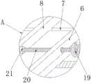
FIG. 2 is an enlarged view of the intelligent glue applicator at A in FIG. 1;
FIG. 3 is a schematic structural diagram of a positioning mechanism in an intelligent glue applicator;
fig. 4 is a schematic structural diagram of a gluing mechanism in an intelligent gluing device.
In the figure: 1. a support plate; 2. a drive motor; 3. a transmission screw rod; 4. a slide rail; 5. gluing a board; 6. fixing the clamping plate; 7. a chute; 8. a sliding clamping plate; 9. a liquid pushing air pressure rod; 10. a glue tank; 11. feeding a rubber tube; 12. an exhaust valve; 13. a glue discharging hose; 14. a gluing motor; 15. a limiting air pressure rod; 16. a support frame; 17. a clamping plate; 18. rolling and coating a glue column; 19. rotating the handle; 20. screwing the screw rod; 21. a bearing; 22. pushing the liquid column; 23. and a pressure detection meter.
Detailed Description
Referring to fig. 1 to 4, in the embodiment of the present invention, an intelligent glue spreading device includes a support plate 1, a slide rail 4 is fixed above the support plate 1 at a front position, a transmission screw 3 is rotatably connected above the support plate 1 at an inner side of the slide rail 4, a transmission motor 2 is fixed at a top end of the transmission screw 3, a glue spreading plate 5 is clamped above the slide rail 4, a sleeve nut is fixed at a middle position of a bottom end of the glue spreading plate 5, the glue spreading plate 5 and the transmission motor 2 are rotatably connected with the transmission screw 3 through the sleeve nut, clamping grooves adapted to the slide rail 4 are formed at front and rear sides of the bottom end of the glue spreading plate 5, the glue spreading plate 5 is clamped with the slide rail 4 through the clamping grooves, after a communication device housing is fixed, the transmission motor 2 operates to drive the transmission screw 3 to rotate, and is in sleeve connection with the transmission screw 3 through the sleeve nut at the middle, under the block of spreading board 5 and slide rail 4, drive spreading board 5 and slide, convey the communication equipment shell to the rubber coating below the rubber coating mechanism and carry out the rubber coating and handle.
A positioning mechanism is arranged above the rubber coating plate 5 and comprises fixed clamping plates 6 fixed on two sides of the rubber coating plate 5, one side of each fixed clamping plate 6 is provided with a sliding groove 7, one side of each fixed clamping plate 6 is connected with a twisting screw rod 20 at the middle position, one end of each twisting screw rod 20 is fixed with a rotating handle 19, the other end of each twisting screw rod 20 is rotatably connected with a bearing 21, the inner side of each sliding groove 7 is clamped with a sliding clamping plate 8, each sliding clamping plate 8 is connected with each twisting screw rod 20 through the bearing 21, the middle part of each fixed clamping plate 6 is provided with an internal thread meshed with each twisting screw rod 20, each fixed clamping plate 6 is rotatably screwed with each twisting screw rod 20 through the internal thread, when the communication equipment shell is coated with rubber, the communication equipment shell is placed on the rubber coating plate 5, each hand-operated rotating handle 19 drives each twisting screw rod 20 to rotate, and under the connection of the clamping of the sliding grooves 7 and the bearings, promote slip cardboard 8 and remove to the communications facilities shell direction, carry out the block to the communications facilities shell fixed, fix a position the rubber coating position of communications facilities shell simultaneously, and then through the block of positioning mechanism to the communications facilities shell, can guarantee rubber coating in-process rubber coated stability, and through the regulation to positioning mechanism, can carry out the block to the communications facilities of different models fixed, and then improved the rubber coating ability of rubber coating device.
A glue tank 10 is fixed at the position of the rear side above a support plate 1, a support frame 16 is fixed at one side of the glue tank 10 above the support plate 1, a liquid pushing air pressure rod 9 is embedded into one side of the glue tank 10, a liquid pushing column 22 is clamped at the telescopic end of the liquid pushing air pressure rod 9 at the inner side of the glue tank 10, a rubber inlet pipe 11 is arranged at one side of the glue tank 10, an exhaust valve 12 is arranged at the other side of the glue tank 10, a pressure detection meter 23 is connected to one side of the exhaust valve 12, a glue coating mechanism is embedded into the top end of the support frame 16 and connected with the glue tank 10 through a glue discharging hose 13, the liquid pushing column 22 is of a conical structure, the outer diameter of the liquid pushing column 22 is matched with the inner diameter of the glue tank 10, the glue discharging hose 13 is a stainless steel corrugated pipe, the length of the glue discharging hose 13 is not less than 1.5m, when a communication equipment shell is coated with, make the glue solution flow into to glue jar 10 in from advancing rubber tube 11, after the glue solution is carried, close discharge valve 12, the flexible end that pushes away liquid pneumatic rod 9 stretches out, promote the propelling movement post 22 and promote forward, carry out extrusion formula propelling movement to the glue solution in gluing jar 10, the glue solution is arranged to the rubber coating mechanism through the rubber hose 13 of arranging of stainless steel corrugated pipe material, and then promote the extrusion formula conveying of propelling movement post 22 to the glue solution in gluing jar 10 through pushing away liquid pneumatic rod 9, can guarantee rubber coating mechanism rubber coating high efficiency, all-round ability, and then improve rubber coating device's rubber coating efficiency, avoid the rubber coating in-process bubble, the condition of leaking scribbling.
The gluing mechanism comprises a limiting air pressure rod 15 embedded at the top end of a support frame 16, a clamping plate 17 is fixed at the telescopic end of the limiting air pressure rod 15, a rolling gluing column 18 is rotatably connected at the inner side of the clamping plate 17, a gluing motor 14 is fixed at the front side of the clamping plate 17 at the top end of the rolling gluing column 18, the rolling gluing column 18 is connected with a glue tank 10 through a glue discharging hose 13, a gluing hole is formed in the outer side of the rolling gluing column 18, a pinhole is formed in the top end of the rolling gluing column 18, the rolling gluing column 18 is fixedly clamped with the gluing motor 14 through the pinhole, when a communication equipment shell is glued, the telescopic end of the limiting air pressure rod 15 extends out to drive the clamping plate 17 to move downwards so as to drive the rolling gluing column 18 to move downwards to glue the communication equipment shell, the rolling gluing column 18 is driven by the gluing motor 14 to rotate and the transmission motor 2 to drive the gluing plate 5 to move horizontally, and carrying out omnibearing gluing on the shell of the communication equipment.
The working principle of the invention is as follows: when gluing the communication equipment shell, the communication equipment shell is placed on a glue spreading plate 5, a handle 19 is rotated by hand to drive a screwing screw rod 20 to rotate, under the connection of the clamping of a chute 7 and a bearing 21, a sliding clamping plate 8 is pushed to move towards the communication equipment shell, the communication equipment shell is clamped and fixed, meanwhile, the gluing position of the communication equipment shell is positioned, a further transmission motor 2 works to drive a transmission screw rod 3 to rotate, the glue spreading plate 5 is driven to slide under the clamping of the glue spreading plate 5 and a sliding rail 4 through the sleeve joint of a sleeve nut at the middle part of the bottom end of the glue spreading plate 5 and the transmission screw rod 3, the communication equipment shell is conveyed to the lower part of a gluing mechanism to be glued, when the communication equipment shell is glued, an exhaust valve 12 is opened to enable glue to flow into a glue tank 10 from a glue inlet pipe 11, the exhaust valve 12 is closed after the glue is conveyed, the flexible end that pushes away liquid pneumatic rod 9 stretches out, it promotes to push away liquid post 22 forward, carry out extrusion formula propelling movement to the glue solution in gluing jar 10, the glue solution is arranged to the rubber coating mechanism through the adhesive discharge hose 13 of stainless steel corrugated pipe material, the flexible end of further spacing pneumatic rod 15 stretches out, drive block board 17 and move down, and then drive roll rubber coating post 18 and move down, carry out the rubber coating to the communications facilities shell, drive roll rubber coating post 18 through rubber coating motor 14 and rotate and drive motor 2 drives the translation of rubber coating board 5, carry out the omnidirectional rubber coating to the communications facilities shell.
The above description is only for the preferred embodiment of the present invention, but the scope of the present invention is not limited thereto, and any person skilled in the art should be considered to be within the technical scope of the present invention, and the technical solutions and the inventive concepts thereof according to the present invention are equivalent to or changed within the technical scope of the present invention.
Claims (9)
1. An intelligent gluing device comprises a support plate (1) and is characterized in that a slide rail (4) is fixed at a position, located on the front side, above the support plate (1), a transmission lead screw (3) is rotatably connected to the inner side, located on the slide rail (4), of the upper side of the support plate (1), a transmission motor (2) is fixed at the top end of the transmission lead screw (3), a gluing plate (5) is clamped above the slide rail (4), a positioning mechanism is arranged above the gluing plate (5), a glue tank (10) is fixed at a position, located on the rear side, above the support plate (1), a support frame (16) is fixed at one side, located on the glue tank (10), of the upper side of the glue tank (10), a liquid pushing air pressure rod (9) is embedded into one side of the glue tank (10), and a liquid pushing column (22) is clamped at a telescopic end, located on the liquid pushing air pressure rod (9), of the inner side of the glue, the top of gluing jar (10) is located one side and is provided with into rubber tube (11), and the top of gluing jar (10) is located the opposite side and is provided with discharge valve (12), one side of discharge valve (12) is connected with pressure measurement table (23), the top embedding of support frame (16) is provided with rubber coating mechanism, rubber coating mechanism is connected with gluey jar (10) through arranging gluey hose (13).
2. The intelligent gluing device as claimed in claim 1, wherein the positioning mechanism comprises a fixing clamping plate (6) fixed on two sides of the gluing plate (5), a sliding groove (7) is formed in one side of the fixing clamping plate (6), a screwing screw rod (20) is connected to the middle position of one side of the fixing clamping plate (6), a rotating handle (19) is fixed to one end of the screwing screw rod (20), a bearing (21) is rotatably connected to the other end of the screwing screw rod (20), a sliding clamping plate (8) is clamped on the inner side of the sliding groove (7), and the sliding clamping plate (8) is connected with the screwing screw rod (20) through the bearing (21).
3. An intelligent gluing device according to claim 1, wherein the gluing mechanism comprises a limiting air pressure rod (15) embedded in the top end of the support frame (16), a clamping plate (17) is fixed to the telescopic end of the limiting air pressure rod (15), a rolling gluing column (18) is rotatably connected to the inner side of the clamping plate (17), a gluing motor (14) is fixed to the front side of the clamping plate (17) and located at the top end of the rolling gluing column (18), and the rolling gluing column (18) is connected with the glue tank (10) through a glue discharging hose (13).
4. An intelligent gluing device as claimed in claim 2, wherein a sleeve nut is fixed at the middle position of the bottom end of the gluing plate (5), and the gluing plate (5) and the transmission motor (2) are rotatably connected through the sleeve nut and the transmission screw rod (3).
5. The intelligent gluing device according to claim 2, wherein the bottom end of the gluing plate (5) is provided with clamping grooves matched with the sliding rails (4) at the front side and the rear side, and the gluing plate (5) is clamped with the sliding rails (4) through the clamping grooves.
6. An intelligent gluing device as claimed in claim 2, wherein the middle part of the fixing clamping plate (6) is provided with an internal thread meshed with the screwing screw rod (20), and the fixing clamping plate (6) is screwed with the screwing screw rod (20) through the internal thread to rotate.
7. An intelligent glue spreading device according to claim 1, wherein the push liquid column (22) is of a conical structure, and the outer diameter of the push liquid column (22) is matched with the inner diameter of the glue pot (10).
8. An intelligent glue spreading device according to claim 1, wherein the glue discharging hose (13) is a stainless steel corrugated pipe, and the length of the glue discharging hose (13) is not less than 1.5 m.
9. An intelligent gluing device as claimed in claim 3, wherein the outside of the rolling gluing column (18) is provided with a gluing hole, the top end of the rolling gluing column (18) is provided with a pin hole, and the rolling gluing column (18) is fixed with the gluing motor (14) in a clamping manner through the pin hole.
Priority Applications (1)
| Application Number | Priority Date | Filing Date | Title |
|---|---|---|---|
| CN201911160302.4A CN110976183A (en) | 2019-11-23 | 2019-11-23 | Intelligent gluing device |
Applications Claiming Priority (1)
| Application Number | Priority Date | Filing Date | Title |
|---|---|---|---|
| CN201911160302.4A CN110976183A (en) | 2019-11-23 | 2019-11-23 | Intelligent gluing device |
Publications (1)
| Publication Number | Publication Date |
|---|---|
| CN110976183A true CN110976183A (en) | 2020-04-10 |
Family
ID=70086131
Family Applications (1)
| Application Number | Title | Priority Date | Filing Date |
|---|---|---|---|
| CN201911160302.4A Pending CN110976183A (en) | 2019-11-23 | 2019-11-23 | Intelligent gluing device |
Country Status (1)
| Country | Link |
|---|---|
| CN (1) | CN110976183A (en) |
Cited By (1)
| Publication number | Priority date | Publication date | Assignee | Title |
|---|---|---|---|---|
| CN112317224A (en) * | 2020-10-29 | 2021-02-05 | 合肥百盛食品有限公司 | Box pasting machine feeding device for food packaging box production |
Citations (8)
| Publication number | Priority date | Publication date | Assignee | Title |
|---|---|---|---|---|
| US3327906A (en) * | 1964-11-07 | 1967-06-27 | Hauni Korber & Co K G | Apparatus for dispensing paste |
| CN201832770U (en) * | 2010-07-22 | 2011-05-18 | 浙江广涛卫厨有限公司 | Glue dispensing and charging bucket |
| CN103537410A (en) * | 2013-09-30 | 2014-01-29 | 中天联合节能建设发展(天津)有限公司 | Glue brushing tool |
| CN204892246U (en) * | 2015-08-29 | 2015-12-23 | 徐州佳美木业有限公司 | Supply to glue even stable timber rubber coating device |
| CN207371790U (en) * | 2017-08-30 | 2018-05-18 | 平湖市新保纺织科技有限公司 | A kind of gluing roller arrangement for heating compounding machine |
| CN108080206A (en) * | 2016-11-22 | 2018-05-29 | 天津汇通中博印铁有限公司 | A kind of glue spreader for paint metals plate |
| CN207667880U (en) * | 2017-11-15 | 2018-07-31 | 安徽邦尼特轨道装备有限公司 | One kind can transverse shifting spray painting clamping tooling |
| CN109174570A (en) * | 2018-09-19 | 2019-01-11 | 安徽宇臻实业有限公司 | A kind of glass glue-spreading tooling |
-
2019
- 2019-11-23 CN CN201911160302.4A patent/CN110976183A/en active Pending
Patent Citations (8)
| Publication number | Priority date | Publication date | Assignee | Title |
|---|---|---|---|---|
| US3327906A (en) * | 1964-11-07 | 1967-06-27 | Hauni Korber & Co K G | Apparatus for dispensing paste |
| CN201832770U (en) * | 2010-07-22 | 2011-05-18 | 浙江广涛卫厨有限公司 | Glue dispensing and charging bucket |
| CN103537410A (en) * | 2013-09-30 | 2014-01-29 | 中天联合节能建设发展(天津)有限公司 | Glue brushing tool |
| CN204892246U (en) * | 2015-08-29 | 2015-12-23 | 徐州佳美木业有限公司 | Supply to glue even stable timber rubber coating device |
| CN108080206A (en) * | 2016-11-22 | 2018-05-29 | 天津汇通中博印铁有限公司 | A kind of glue spreader for paint metals plate |
| CN207371790U (en) * | 2017-08-30 | 2018-05-18 | 平湖市新保纺织科技有限公司 | A kind of gluing roller arrangement for heating compounding machine |
| CN207667880U (en) * | 2017-11-15 | 2018-07-31 | 安徽邦尼特轨道装备有限公司 | One kind can transverse shifting spray painting clamping tooling |
| CN109174570A (en) * | 2018-09-19 | 2019-01-11 | 安徽宇臻实业有限公司 | A kind of glass glue-spreading tooling |
Cited By (1)
| Publication number | Priority date | Publication date | Assignee | Title |
|---|---|---|---|---|
| CN112317224A (en) * | 2020-10-29 | 2021-02-05 | 合肥百盛食品有限公司 | Box pasting machine feeding device for food packaging box production |
Similar Documents
| Publication | Publication Date | Title |
|---|---|---|
| CN204911908U (en) | Steel pipe paint spraying machine | |
| CN204933810U (en) | One is steel pipe paint sprayer easily | |
| CN209567118U (en) | A kind of novel aerosol filling apparatus | |
| CN110976183A (en) | Intelligent gluing device | |
| CN204911909U (en) | Novel steel pipe paint spraying machine | |
| CN206495770U (en) | A kind of peristaltic pump is used for the adjustable apparatus fed | |
| CN209465266U (en) | A kind of anti-oxidation process for producing equipment of multifunctional plate | |
| CN204911890U (en) | Steel pipe paint spraying machine of adjustable angle of spraying paint | |
| CN204911878U (en) | Environment -friendly steel pipe paint spraying machine | |
| CN211085585U (en) | Leak detection device of refrigeration pipeline for air conditioner production | |
| CN204933791U (en) | A kind of steel pipe paint sprayer of raising the efficiency | |
| CN209577282U (en) | Straight steel pipe gluing compaction apparatus | |
| CN209697242U (en) | A kind of container bottom board processing adhesive spray equipment of adjustable spray range | |
| CN216965026U (en) | Pipeline spraying equipment | |
| CN207582905U (en) | A kind of multi-functional production aqueous latex paint storage device | |
| CN218493767U (en) | Peristaltic pump multichannel feeding device is used in polycarboxylate water reducing agent processing | |
| CN210911336U (en) | A rubber coating mechanism for packing box production | |
| CN210545859U (en) | Spraying device for wood working | |
| CN113880449A (en) | Glass coating clamp and coating system thereof | |
| CN203826414U (en) | Automatic gluing machine for back membrane | |
| CN208248974U (en) | A kind of emulsion storage device | |
| CN207308452U (en) | A kind of plug cleaning machine | |
| CN220160306U (en) | Positioning table for tile surface spraying | |
| CN204911891U (en) | Adjustable limit cheng gangguan paint spraying machine | |
| CN204911879U (en) | Service life of is prolonged steel pipe paint spraying machine |
Legal Events
| Date | Code | Title | Description |
|---|---|---|---|
| PB01 | Publication | ||
| PB01 | Publication | ||
| SE01 | Entry into force of request for substantive examination | ||
| SE01 | Entry into force of request for substantive examination | ||
| RJ01 | Rejection of invention patent application after publication |
Application publication date: 20200410 |
|
| RJ01 | Rejection of invention patent application after publication |