CN110970777A - Instrument socket, instrument plug and instrument plugging system - Google Patents
Instrument socket, instrument plug and instrument plugging system Download PDFInfo
- Publication number
- CN110970777A CN110970777A CN201910935027.2A CN201910935027A CN110970777A CN 110970777 A CN110970777 A CN 110970777A CN 201910935027 A CN201910935027 A CN 201910935027A CN 110970777 A CN110970777 A CN 110970777A
- Authority
- CN
- China
- Prior art keywords
- instrument
- plug
- receptacle
- cylindrical shape
- socket
- Prior art date
- Legal status (The legal status is an assumption and is not a legal conclusion. Google has not performed a legal analysis and makes no representation as to the accuracy of the status listed.)
- Pending
Links
Images


Classifications
-
- H—ELECTRICITY
- H01—ELECTRIC ELEMENTS
- H01R—ELECTRICALLY-CONDUCTIVE CONNECTIONS; STRUCTURAL ASSOCIATIONS OF A PLURALITY OF MUTUALLY-INSULATED ELECTRICAL CONNECTING ELEMENTS; COUPLING DEVICES; CURRENT COLLECTORS
- H01R24/00—Two-part coupling devices, or either of their cooperating parts, characterised by their overall structure
- H01R24/76—Two-part coupling devices, or either of their cooperating parts, characterised by their overall structure with sockets, clips or analogous contacts and secured to apparatus or structure, e.g. to a wall
-
- H—ELECTRICITY
- H01—ELECTRIC ELEMENTS
- H01R—ELECTRICALLY-CONDUCTIVE CONNECTIONS; STRUCTURAL ASSOCIATIONS OF A PLURALITY OF MUTUALLY-INSULATED ELECTRICAL CONNECTING ELEMENTS; COUPLING DEVICES; CURRENT COLLECTORS
- H01R13/00—Details of coupling devices of the kinds covered by groups H01R12/70 or H01R24/00 - H01R33/00
- H01R13/73—Means for mounting coupling parts to apparatus or structures, e.g. to a wall
- H01R13/74—Means for mounting coupling parts in openings of a panel
- H01R13/741—Means for mounting coupling parts in openings of a panel using snap fastening means
- H01R13/743—Means for mounting coupling parts in openings of a panel using snap fastening means integral with the housing
-
- H—ELECTRICITY
- H01—ELECTRIC ELEMENTS
- H01R—ELECTRICALLY-CONDUCTIVE CONNECTIONS; STRUCTURAL ASSOCIATIONS OF A PLURALITY OF MUTUALLY-INSULATED ELECTRICAL CONNECTING ELEMENTS; COUPLING DEVICES; CURRENT COLLECTORS
- H01R13/00—Details of coupling devices of the kinds covered by groups H01R12/70 or H01R24/00 - H01R33/00
- H01R13/46—Bases; Cases
-
- H—ELECTRICITY
- H01—ELECTRIC ELEMENTS
- H01R—ELECTRICALLY-CONDUCTIVE CONNECTIONS; STRUCTURAL ASSOCIATIONS OF A PLURALITY OF MUTUALLY-INSULATED ELECTRICAL CONNECTING ELEMENTS; COUPLING DEVICES; CURRENT COLLECTORS
- H01R13/00—Details of coupling devices of the kinds covered by groups H01R12/70 or H01R24/00 - H01R33/00
- H01R13/62—Means for facilitating engagement or disengagement of coupling parts or for holding them in engagement
- H01R13/627—Snap or like fastening
-
- H—ELECTRICITY
- H01—ELECTRIC ELEMENTS
- H01R—ELECTRICALLY-CONDUCTIVE CONNECTIONS; STRUCTURAL ASSOCIATIONS OF A PLURALITY OF MUTUALLY-INSULATED ELECTRICAL CONNECTING ELEMENTS; COUPLING DEVICES; CURRENT COLLECTORS
- H01R13/00—Details of coupling devices of the kinds covered by groups H01R12/70 or H01R24/00 - H01R33/00
- H01R13/62—Means for facilitating engagement or disengagement of coupling parts or for holding them in engagement
- H01R13/639—Additional means for holding or locking coupling parts together, after engagement, e.g. separate keylock, retainer strap
-
- H—ELECTRICITY
- H01—ELECTRIC ELEMENTS
- H01R—ELECTRICALLY-CONDUCTIVE CONNECTIONS; STRUCTURAL ASSOCIATIONS OF A PLURALITY OF MUTUALLY-INSULATED ELECTRICAL CONNECTING ELEMENTS; COUPLING DEVICES; CURRENT COLLECTORS
- H01R13/00—Details of coupling devices of the kinds covered by groups H01R12/70 or H01R24/00 - H01R33/00
- H01R13/648—Protective earth or shield arrangements on coupling devices, e.g. anti-static shielding
- H01R13/652—Protective earth or shield arrangements on coupling devices, e.g. anti-static shielding with earth pin, blade or socket
-
- H—ELECTRICITY
- H01—ELECTRIC ELEMENTS
- H01R—ELECTRICALLY-CONDUCTIVE CONNECTIONS; STRUCTURAL ASSOCIATIONS OF A PLURALITY OF MUTUALLY-INSULATED ELECTRICAL CONNECTING ELEMENTS; COUPLING DEVICES; CURRENT COLLECTORS
- H01R13/00—Details of coupling devices of the kinds covered by groups H01R12/70 or H01R24/00 - H01R33/00
- H01R13/648—Protective earth or shield arrangements on coupling devices, e.g. anti-static shielding
- H01R13/655—Protective earth or shield arrangements on coupling devices, e.g. anti-static shielding with earth brace
-
- H—ELECTRICITY
- H01—ELECTRIC ELEMENTS
- H01R—ELECTRICALLY-CONDUCTIVE CONNECTIONS; STRUCTURAL ASSOCIATIONS OF A PLURALITY OF MUTUALLY-INSULATED ELECTRICAL CONNECTING ELEMENTS; COUPLING DEVICES; CURRENT COLLECTORS
- H01R13/00—Details of coupling devices of the kinds covered by groups H01R12/70 or H01R24/00 - H01R33/00
- H01R13/62—Means for facilitating engagement or disengagement of coupling parts or for holding them in engagement
- H01R13/627—Snap or like fastening
- H01R13/6271—Latching means integral with the housing
- H01R13/6272—Latching means integral with the housing comprising a single latching arm
Abstract
The invention relates to an instrument socket, an instrument plug and an instrument plugging system. An instrument receptacle (100) for detachably fastening in an opening (700) of an electrical instrument has an outer wall (120) which extends at least partially along a cylindrical shape (F) and furthermore within the cylindrical shape. A plug receiving chamber (150) is surrounded by the outer wall (120) and has an insertion opening (151) for inserting a plug (500) in an insertion direction (E), the plug receiving chamber (150) extending from the insertion opening. At least two electrical contacts (200,202,205) arranged within the cylindrical shape (F) and extending to conductively contact a plug (500) inserted through the insertion aperture (151), wherein one of the contacts (200,202,205) is a ground contact (205); a ground terminal (251) is electrically connected to the ground contact (205) and extends laterally out in a direction outwardly from the outer wall (120) and substantially perpendicularly from an axis of rotational symmetry of the cylindrical shape (F).
Description
Technical Field
The invention relates to an instrument socket, an instrument plug and an instrument plugging system consisting of the instrument socket and the instrument plug.
Background
It is known from the prior art to use wire sockets for connecting instrument-side wires to instrument-outside wires. To this end, a wire receptacle is typically provided in an opening in the wall of the instrument housing to provide a wire connection. The instrument external wires are fixed in the wire receptacle by means of clamping screws. The instrument-side wires may be coupled to the wire receptacles by means of a flat plug or soldered connection. This results in an electrically conductive connection between the instrument-side electrical line and the instrument-outside electrical line.
It has been shown that there may be disadvantages to such instrument electrical connections. Therefore, the connection of the respective wires to the wire sockets requires many manual steps. There is also a higher risk that the respective wires are not sufficiently firmly fixed in the wire receptacle, the wires may therefore loosen and the electrical connection is at least sometimes interrupted. This may lead to temporary failure or malfunction of the instrument. Furthermore, there is usually only a very limited space for the respective wires in the wire socket via the opening, since the opening is usually designed to be small (opening diameter of less than 10 cm) depending on technology and/or in view of appearance. This makes installation particularly difficult. To this end, the electrical line socket usually has a comparatively large installation space compared to the size of the opening on the side thereof provided for connecting the external electrical lines of the instrument. As a result, the appearance of the instrument thus connected is impaired and its structural requirements are increased. In addition, grounding contacts need to be provided, particularly for metal instrument housings, to prevent dangerous electrical leakage or arcing from striking the user. The ground contact is usually screwed to the housing as a separate ground conductor. But there is then a risk that the separate earth wire becomes loose. In addition, the appearance of the instrument is impaired by the ground lead protruding outside the case.
Disclosure of Invention
It is therefore the object of the present invention to provide a device and a system, by means of which the aforementioned disadvantages of the solutions known from the prior art are overcome.
In particular, the object of the invention is to provide an electrical connection of instrument-side electrical lines to instrument-external electrical lines, wherein the provision of said connection should require as little installation space as possible and should allow rapid installation and removal from the instrument. Furthermore, it should be possible for the installation space defined by the openings to be used as optimally as possible for connecting the individual lines.
A first aspect of the invention relates to an instrument socket for detachably securing within an aperture of a powered instrument.
The instrument socket comprises a socket body with an outer wall which at least partially follows the cylindrical shape and furthermore extends within the cylindrical shape. The socket body further has a plug accommodating chamber surrounded by the outer wall and having an insertion hole into which the plug is inserted in an insertion direction, the plug accommodating chamber extending from the insertion hole.
The instrument socket also has at least two electrical contacts disposed within the cylindrical shape and extending to conductively contact a plug inserted through the insertion aperture. One of the contacts is now a ground contact.
The instrument receptacle also has a ground terminal (Erdungsanschluss) electrically connected with the ground contact and extending laterally in an outward direction from the outer wall and substantially perpendicular to the axis of rotational symmetry of the cylindrical shape.
According to the invention, the instrument socket provides a simple connection possibility for instrument-side and instrument-external wires. In this case, the number of installation steps for connecting the respective line contacts and the complexity of the installation can be significantly reduced in comparison with screw-clamping connections known from the prior art. The risk of mounting errors and/or mounting inaccuracies can thus also be reduced. In addition, the special shaping of the socket body, which extends at least partially in the (virtual) cylindrical shape, makes it possible to obtain the functionality required for the instrument socket, which is available compactly in a defined installation space. Thus, the installation space required for the instrument socket can be reduced. In addition, the safety-relevant components are defined by the ground terminals in a simple manner with respect to the socket body and are provided in a compact manner. It is thus also possible to provide a terminal on the ground contact, which terminal is separate from the socket body, for example in order to contact the housing wall of the instrument and to be electrically connected to the ground contact. In addition, a rotation preventing member may be provided by providing the ground terminal according to the present invention. For this purpose, the ground terminal can cooperate with the wall of the device housing, for example, or with the aid of additional fastening means or fastening structures, in such a way that the device receptacle is prevented from rotating.
The instrument socket according to the invention thus provides a (rotation-proof) connection possibility of the instrument-side electrical lines and the instrument-outside electrical lines via the openings, which overcomes the above-mentioned disadvantages of the solutions known from the prior art.
According to an advantageous development, the socket body can have a circular contour, preferably viewed in the insertion direction, in the region of the outer wall which extends here in the cylindrical shape, the circular diameter of which is in the range from 10mm to 100 mm. Alternatively or additionally, the cylindrical shape may have a diameter in the range of 10mm-100 mm. Furthermore, the socket body may alternatively or additionally extend longitudinally along the axis of rotational symmetry, preferably with a longitudinal extension in the range of 10-100 mm.
This makes it possible, for example, for the instrument receptacle to be used for a plurality of different, in particular conventional, openings. In addition, the instrument socket requires the smallest possible installation space. Thereby, the appearance of the instrument to be connected can be improved and the effective structural space thereof can be reduced.
According to a further advantageous development, the socket body or its outer wall can have, within the cylindrical shape, two preferably opposite and also preferably parallel and in particular straight sections which are connected by at least one second section (or preferably two second sections which are preferably opposite about the axis of rotational symmetry and extend substantially in the shape of a cylinder). In this case, the first section and/or the second section may be arranged evenly distributed around the socket body or the cylindrical shape.
The socket body can thus have at least two straight, opposite first sections which are connected by a second section which extends at least along the cylindrical shape. This makes it possible, for example, for the socket body to be accommodated in a substantially circular opening in a non-rotatable manner. Thus, the prevention of rotation can be provided with simple means. In addition, the installation space required for the instrument receptacle can be further reduced by providing a straight first section. Finally, the installation of the plug is also simplified, since the instrument socket can better engage the straight section.
According to an advantageous development, the ground terminal can extend from one of the second sections.
This makes it possible, for example, for the instrument receptacle to have an orientation. The ground terminal can then serve as coding means in addition to the function of providing an (external/additional) connection for the ground contact, in order to unambiguously position the instrument socket in the opening. It is also possible that the structural space saving and the mounting simplification obtained by the provision of the first section are not adversely affected by the ground terminal. The compactness and installability of the instrument receptacle is therefore further improved by the arrangement chosen.
According to a further advantageous development, the ground terminal can extend in the form of a surface, preferably in a plane perpendicular to the axis of rotational symmetry and/or in a plane perpendicular to the insertion direction.
Thus, the ground terminal may be disposed, for example, parallel to a plane in which the insertion hole is also provided. This is particularly advantageous because it allows electrical conduction to the wall of the device housing with the opening, and this is done with simple constructional measures. In addition, the contact area with the wall can be increased by providing a flat ground terminal, thus improving the electrical connection of the two members.
According to an advantageous development, the ground terminal can be connected to the ground contact by means of a connecting portion to form a ground contact element. The ground terminal and the ground contact may be integrally formed with each other by a connecting portion. Alternatively or additionally, the contact and preferably the ground contact element can be designed as stamped and bent parts for this purpose.
By means of the design according to the invention, it is possible in this case, for example, to achieve a reliable mechanical and electrical connection of the ground terminal and the ground contact to one another. In addition, the manufacture and installation of the respective components can be simplified, and thus the cost can be reduced.
The connecting portion may also extend longitudinally, preferably laterally along the outer wall and preferably substantially parallel to the axis of rotational symmetry. Furthermore, the connecting portion may extend along the second section, which preferably has a ground terminal.
For example, a further contact surface for connection to a ground contact can be provided on an outer wall of the instrument receptacle by means of a connecting portion. This makes it possible to provide a further connection possibility to the ground contact on the outer side of the instrument socket. The functional range of the instrument receptacle can thus be expanded without increasing the installation space of the instrument receptacle.
Alternatively or additionally, the ground terminal can be arranged on a part of the outer wall, preferably on a part of the second section, which is designed as a recess back towards the axis of rotational symmetry with respect to the cylindrical shape. The indentation then extends in a plane parallel to the axis of rotational symmetry. The connection can extend along a back recess and preferably in a cylindrical shape.
It is thus possible, for example, to make optimum use of the space of the socket body defined by the cylindrical shape. In particular, the connection of the ground terminal can be arranged in the recess, without the instrument socket then undergoing an increase in width in the radial direction. Thus, the compact structure and design of the instrument receptacle can be further improved.
According to a further advantageous development, the ground terminal can have at least one, preferably two ground terminal openings, the (geometric shape) center point of which preferably has a distance to the axis of rotational symmetry in the range from 10mm to 50 mm. Preferably, the two ground terminal openings can then be arranged mirror-symmetrically with respect to the ground terminal and/or with respect to a radial direction of the rotational symmetry axis.
By means of the design according to the invention, it is possible in this case, for example, to use the instrument receptacle for conventional openings. In addition, the instrument socket can be compactly provided by sizing. In addition, the ground terminal can be fixed to the device housing wall via a ground terminal opening, for example by means of a screw connection.
According to an advantageous development, the section extending along the cylindrical shape, preferably at least one of the second sections, can extend over an angular range of at least 20 °, or at least 30 °, or at least 40 °, or at least 60 °, or at least 90 °, or at least 120 °, or at least 130 °, as seen in the direction of the rotational symmetry axis.
By means of the design according to the invention, it is possible here, for example, for the second section to have a substantially circular segment-shaped cross-sectional shape. This makes it possible to construct the instrument receptacle as compact as possible and to use it with many common industrial openings.
According to a further advantageous development, the instrument socket can also have a support for receiving the open-pored edge region of the instrument socket (or socket body) against at least part, but preferably at least the back side of the socket body. The support can be formed here preferably by a preferably annular projection (preferably projecting outwards of the socket body) which surrounds the outer wall at least partially in the circumferential direction. It is also preferred that the bearing can have a seal, such as for example a rubber lip, in order to seal the instrument housing against the ingress of dirt and/or moisture.
This makes it possible, for example, for the instrument receptacle to be arranged in the opening by means of a defined region of the receptacle body. In particular, it is possible with the preferred design described above to securely fix the socket body in the opening and to determine the socket body at least with respect to the direction of movement. A preferred mounting direction can also be specified by the design of the instrument socket structure, so that mounting is facilitated. It is also feasible that the instrument socket is also used in applications where higher requirements are placed on instrument tightness, such as IP protection class IP67 and above.
In particular, the support can be arranged at the front end of the socket body, viewed in the insertion direction, and/or in a region of the insertion opening. Alternatively or additionally, the support portion may extend in a plane defined by the insertion aperture. Furthermore, the support can extend in a plane perpendicular to the axis of rotational symmetry and/or in a plane perpendicular to the insertion direction and/or in a plane in which the ground terminal also extends.
In this case, it is possible, for example, by the design according to the invention that the bearing is provided in a plane parallel to the plane defined by the insertion opening. The bearing can thus transmit the mounting forces occurring at the instrument socket when the plug is inserted to the instrument housing wall. Thus, the instrument receptacle can also be used in applications where a plug requires a large insertion force.
According to an advantageous development, the socket body can have a base which preferably delimits the plug receiving chamber on the side opposite the insertion opening.
The dimensions of the plug receiving chamber can be limited, for example. This design also allows the plug to be properly seated in the plug-receiving cavity when the plug is connected to the instrument socket.
According to a further advantageous development, the electrical contact can extend in the plug-in direction, preferably out of the base into the plug receiving space opposite the plug-in direction. The electrical contacts may then preferably project into the insertion opening. Furthermore, the electrical contacts can preferably extend in or through the socket body, in particular through the bottom thereof. The electrical contacts can preferably be arranged side by side, in particular with respect to the longitudinal direction of the plug receiving chamber.
For example, it is possible to provide electrical contacts in the plug receiving space as required, while at the same time being shielded from damage and external influences. Furthermore, it is possible to use the plug receiving space for guiding the plug to the electrical contact by means of this design.
According to a further advantageous development, the electrical contact and/or the ground terminal can be detachably connected to the socket body. Preferably, they can be detachably received or detachably held in through holes which communicate the plug receiving chamber to the back side of the socket body, preferably through the bottom.
It is thus possible, for example, to separate the ground terminal from the instrument socket as required, in order thus to design the instrument socket more compactly, for example. The ground terminal may in this case be provided, for example, by a connection portion, or merely by means of another connection to the ground contact. It is also possible, for example, for the instrument socket to be adapted to different plug types. The functionality and versatility of the instrument receptacle may thus be improved.
According to an advantageous further development, each electrical contact can have a plug contact portion for electrically contacting a plug inserted via the insertion opening and at least one device connection portion for connecting the electrical contact. The plug contact part can preferably face the plug receiving space or project into it. In addition, the instrument connection portion may preferably be provided exposed at the back side or accessible from the back side. The instrument connection can preferably be designed as a plug or as a soldered lead.
It is thus possible, for example, to provide the connection of the instrument-side electrical lines and the instrument-outside electrical lines in a simple manner and with low space requirements. In addition, the installation and (wire) connection of the instrument socket can be simplified.
According to a further advantageous development, the electrical contact can extend in a plane which preferably extends along or parallel to the axis of rotational symmetry and/or the insertion direction. Alternatively or additionally, the electrical contact may have an elongated I-shape or Y-shape or a curved L-shape or T-shape. In this case, the plug contact portion can be arranged at one end, and the at least one device connection portion can be arranged at the end of the respective electrical contact which is opposite to the plug contact portion. In addition, the instrument connections can preferably extend away from one another in the opposite direction in the case of a T-shape and enclose an angle of less than 180 ° in the case of a Y-shape and preferably extend parallel to one another. It is also conceivable, however, for the respective electrical contacts to have various different forms or combinations of the forms mentioned.
Thus, for example, electrical contacts for connecting instrument-side lines can be provided on the rear side of the instrument socket in a simple manner, which has low space requirements and simplifies the installation. In addition, the respective contact can be produced in a simple manner, for example as a stamped and bent part. Thus, costs can also be reduced.
According to an advantageous development, the plug receiving space can have a substantially elongate and/or rectangular and/or asymmetrical, in particular rotationally asymmetrical, cross section, as seen in the plug-in direction. In this case, preferably, the longitudinal side of the plug receiving space can face the first section, while the narrow side of the plug receiving space faces the second section. The plug receiving cavity may preferably have at least one male edge portion. The male lip portion may also be opposed to the ground terminal, preferably with respect to the plug receiving cavity.
By designing the plug receiving cavity with a rectangular cross-sectional shape, the plug can for example be prevented from being inserted in an incorrect orientation with respect to both insertion directions. It is also possible to facilitate mounting aids in which the plug receiving chamber has an asymmetrical cross section or at least one convex edge portion in order to thus clearly determine the plug orientation during insertion. In addition, the orientation of the instrument socket can be identified with this preferred plug receiving cavity design for installation into the opening, thus facilitating instrument socket installation.
According to a further advantageous development, the plug receptacle can have at least one coding structure, which is designed to correspond to a coding structure counterpart of a plug inserted into the plug receptacle in such a way that only the connection of the instrument receptacle with a suitable plug is permitted. Preferably, the coding structure can be designed as a projection, particularly preferably, the coding structure is arranged in a convex edge section. The coding structure can preferably extend longitudinally in the insertion direction or in the direction of the rotational axis of symmetry.
It is thus possible, for example, to provide a defined coding structure in the plug receiving space, whereby improper insertion of the electrical line into the instrument socket can be prevented. Thus, for example, the instrument receptacle can have a coding structure which only allows the insertion of wires which are suitable for conducting a defined (minimum) current intensity. However, it is also possible to provide the coding structure in such a way that the electrical lines suitable for carrying currents exceeding the (minimum) current intensity are also compatible with the instrument socket (upward compatibility). For this purpose, a principle known as error protection can be used to implement the connection of the instrument socket to a plug in a manner that is error-proof. It is therefore possible to simplify the installation and to provide a less error-prone wire connection by the aforementioned preferred design of the instrument socket.
According to an advantageous development, the instrument receptacle can also have at least one locking element. The locking element can preferably be arranged in the region of the outer wall or extend along the cylindrical shape. The locking element can preferably be arranged movably, in particular rotatably. The locking element may also have a locking projection which projects laterally outwards from the axis of rotational symmetry and preferably projects beyond the cylindrical shape in order to hold the instrument receptacle, preferably detachably, in the opening section following the cylindrical shape or the cross-sectional contour of the outer wall. The outer wall may have a pivot space portion in the region of the locking member, which forms a free space about the cylindrical shape, preferably extending parallel to the axis of rotational symmetry, in order to selectively accommodate the respective locking member to allow its movement or its rotation to allow removal of the mounted instrument socket or the mounted socket body from the opening. In addition, the instrument receptacle can have a plurality of locking elements which are preferably arranged uniformly distributed around the outer wall of the receptacle body.
It is thus possible, for example, to detachably mount the instrument socket in the opening of the wall of the instrument housing by simple means. In this case, a secure fastening in the opening can be achieved in particular in cooperation with the bearing. By the design in the form of a locking element, it is also possible to react flexibly to fluctuations in the thickness of the housing wall of the device. Thus, the instrument socket is variable in wall thickness. In addition, the installation space occupied by the instrument receptacle for the arrangement of the fastening means can be made unnecessarily large by the preferred installation on the outer wall or along a cylindrical shape. Furthermore, the free space which is available through the cooperation and arrangement of the individual components of the instrument socket, such as the outer wall, the plug receiving chamber and the locking element, can be utilized in an elegant manner in order to provide a large number of functions in a compact and cost-effective manner.
The locking element may also form a separate part of the present application.
According to a further advantageous development, the instrument receptacle can also have a plug latching lever with a locking projection which can be moved between a locking position, in which it projects into the plug receptacle space, preferably radially to the axis of rotational symmetry or viewed in the insertion direction with respect to the insertion direction, and an unlocking position, in which it does not project into the plug receptacle space, viewed in the insertion direction. The plug-stop lever can have an elastic part with a fastening end, by means of which the plug-stop lever can be fastened to the socket body or the outer wall. The resilient portion may also have a locking end spaced from or opposite the fixed end, the locking end having a locking projection to rotate the plug stop lever past the fixed end.
It is therefore possible to provide the device socket with means by which a reliable and detachable connection of the device socket to the plug can be achieved. It is thus possible, for example, to obtain a plug-in resistance in the instrument socket in order thus, for example, to prevent the plug from being inadvertently pulled out of the instrument socket. In addition, a structure is also available by the plug stopper lever whereby the plug can be prevented from being inserted into the instrument socket in a wrong orientation. In addition, the instrument socket obtains a marking that can be used for the installation and orientation of the instrument socket in the opening by providing a plug stop lever. The preferred design thus provides a connection that is error-proof while the installation costs are reduced.
The plug stop lever may also form a separate part of the present application.
According to an advantageous development, the locking projection can have a thrust ramp extending obliquely with respect to the plug-in direction and preferably opposite to the plug-in direction to move the plug latching lever from the locking position to the unlocking position exclusively when the plug is inserted into the plug receptacle.
It is therefore possible that the installation and connection of the instrument socket and the plug is simplified. In addition, the risk of damage to the plug stop lever due to plug insertion is reduced.
According to a further advantageous development, the plug stop lever (or in particular the spring) can preferably extend substantially along the rotational symmetry axis from the fixed end to the locking end up to the insertion opening. In this case, the plug latching lever (or at least the spring portion) can preferably be arranged on a plug locking portion of the outer wall (preferably of one of the first sections) which is designed in the form of a recess with respect to the cylindrical shape toward the axis of rotational symmetry, so that the plug latching lever is arranged in the recess in each rotational position (but in particular in the locking position and in the unlocking position).
It is thus possible, for example, for the cylindrical shape of the instrument socket to be retained despite the provision of the plug-arresting lever. Instead, a compact structure of the instrument socket is maintained. In this way, a constant installation space occupied by the instrument receptacle can be maintained despite the increased functionality.
According to a further advantageous development, the plug latching lever can have a grip. The grip portion may preferably extend from the locking end and further preferably opposite to the insertion direction or preferably project from the socket body, so that an operator can move the plug stop lever between the locking position and the unlocking position. In addition, the plug latching lever, preferably the grip, can have a stop which is inclined in the locking position opposite to the insertion direction with respect to a bearing plane perpendicular to the rotational symmetry axis such that the stop extends in the unlocking position in the bearing plane, wherein the bearing plane preferably corresponds to the plane defined by the insertion opening.
It is thus possible, for example, to improve the operability of the plug catch lever. In addition, it is possible to prevent the user from unintentionally pulling the plug stopping rod excessively. In this way, the risk of damage to the instrument socket may be reduced. The installation and functional performance of the instrument socket is thus further improved by the advantageous design.
According to a further advantageous development, the socket body and preferably also the support can be manufactured from plastic. The socket body and the support are then preferably constructed/manufactured integral with each other. In addition, the socket body and/or the support can be made of different materials, in particular a plurality of plastics. Preferably, the socket body and/or the support can be produced by means of an injection molding method, in particular a multi-component injection molding (e.g. two-component injection molding). Preferably, one of the plastics used may be a sealing material. Thus, for example, the support can be formed at least partially (i.e. the entire support or at least a part of the support) as a seal or be produced from a preferably elastic sealing material.
Thus, an electrical insulation and shielding can be obtained by the material of the socket body and possibly of the support. The instrument socket may also be used to seal the instrument housing with a suitable sealing material. It is also possible, for example, for the instrument receptacle to be produced according to an advantageous production method.
A second aspect of the invention relates to another instrument receptacle for detachable securement within an opening of a powered instrument.
The instrument socket has a socket body with an outer wall which extends at least partially along the cylindrical shape and furthermore within the cylindrical shape. The socket body further has a plug-receiving cavity surrounded by the outer wall and having an insertion hole for insertion of a plug in an insertion direction, the plug-receiving cavity extending from the insertion hole.
Further, the instrument receptacle has at least two electrical contacts arranged within the cylindrical shape and extending so as to be in electrically conductive contact with the plug inserted via the insertion hole.
The socket body or its outer wall has, within the cylindrical shape, two first sections which are opposite with respect to the axis of rotational symmetry of the cylindrical shape and are preferably straight in parallel, the first sections being connected by at least two second sections which are opposite with respect to the axis of rotational symmetry and extend substantially along the cylindrical shape.
As already described above for the instrument socket according to the first aspect of the invention, according to the second aspect of the invention, a simple connection possibility with the instrument-side and instrument-outside wires of the instrument socket is also provided. The disadvantages and problems of the solutions known from the prior art can also be overcome here with such an instrument socket.
In particular, the instrument socket now allows, among other things, a reduction in the number of mounting steps for connecting the respective wire contacts and a reduction in the complexity of its mounting.
In addition, the special shape of the socket body makes it possible in particular to provide the functionality required for the instrument socket compactly in a defined installation space and thus to reduce the installation space required for the instrument socket. In addition, this shape allows the instrument receptacle to be used in openings common in many industries. The instrument receptacle can also be accommodated in the opening in a rotationally fixed manner by the form-fit between the instrument receptacle and the opening.
But unlike the instrument socket of the first aspect of the invention, the instrument socket of the second aspect of the invention does not have a ground contact or ground terminal. The rotation prevention of the instrument socket according to the second aspect of the invention can be achieved by a defined design of the socket body. The device socket is used in particular in devices which already have such structural insulation (for example double-insulated plastic housings) or are supplied with such low power that no ground contacts and ground terminals (for the device housing) need be provided.
The instrument socket according to the second aspect of the present invention may naturally have each of the aforementioned features according to the first aspect of the present invention in addition to the ground terminal. These features are for overview only and are not described further.
A third aspect of the invention relates to an instrument plug having a contour corresponding to the plug receiving cavity of one of the aforementioned instrument sockets for receiving the instrument plug in the plug receiving cavity for electrically conductive connection of the instrument socket.
The instrument plug has a locking structure corresponding to the locking projection of the plug latching lever in order to detachably hold the instrument plug in the plug receiving chamber in the locking position of the plug latching lever.
A reliable compact connection with pull-out resistance of the instrument-side and instrument-outside wires of the instrument plug can thus be provided. It is particularly possible for an instrument external cable extending from the instrument plug to be detachably connected to the instrument socket. The construction space required for the connection can be minimized.
According to an advantageous development, the instrument plug can have a coding structure counterpart corresponding to the coding structure of the instrument socket.
This prevents, for example, an unsuitable instrument plug from being inserted into the instrument socket. In this way, for example, the risk of an instrument plug designed for low current intensities being connected to an instrument socket designed for comparatively high current intensities can be reduced.
A fourth aspect of the invention relates to an instrument plug-in system having one of the aforementioned instrument sockets and an instrument plug corresponding to the instrument socket, preferably an instrument plug of the aforementioned manner, for electrically conductively contacting contacts of the instrument socket by accommodating the instrument plug in a plug accommodating chamber.
Thus, a reliable compact connection with resistance to pull-out of the instrument-side electric wire and the instrument-outside electric wire by the instrument socket and the instrument plug can be provided.
The instrument plug-in system can also have all the features of the instrument socket of the first or second aspect of the invention and of the instrument plug described above, which for the sake of overview are not explained again here in detail with the advantages resulting therefrom.
Drawings
Further embodiments and advantages of the invention are explained in conjunction with the following exemplary embodiments and with reference to the figures of the drawings. For purposes of overview, not every feature may be labeled in every drawing. This does not mean that corresponding features are not present in the figures, in which:
fig. 1 shows a perspective view of an instrument receptacle according to a first embodiment (according to a first aspect) of the present invention.
Fig. 2 shows a front view of the instrument receptacle of fig. 1.
Fig. 3 shows a first side view of the instrument receptacle of fig. 1.
Fig. 4 shows a rear view of the instrument receptacle of fig. 1.
Fig. 5 shows a second side view of the instrument receptacle of fig. 1.
Fig. 6 shows a perspective view of the instrument socket of fig. 1, a perspective view of an instrument plug according to an embodiment of the present invention, and a perspective view of an instrument plugging system according to an embodiment of the present invention.
Fig. 7 shows a perspective view of the component parts of fig. 6 in a combined state.
Fig. 8 shows a cross-sectional view of fig. 7.
Fig. 9A to 9C show different (from the prior art) known openings.
Fig. 10 shows a front view of an instrument receptacle according to a second embodiment (according to the second aspect) of the invention.
Fig. 11 shows a front view of an advantageous development of the instrument receptacle of fig. 10, thus according to a third embodiment of the invention (according to the second aspect).
Fig. 12 shows a front view of a further advantageous development of the instrument receptacle of fig. 10, thus according to a fourth embodiment of the invention (according to the second aspect).
Fig. 13 shows a perspective view of the instrument receptacle of fig. 10.
Fig. 14 shows a perspective view of an advantageous development of the instrument receptacle of fig. 10, thus according to a fifth embodiment of the invention (according to the second aspect).
Fig. 15 shows a perspective view of a further advantageous development of the instrument receptacle of fig. 10, thus according to a sixth embodiment of the invention (according to the second aspect).
Detailed Description
Fig. 1 to 5 show different views of an embodiment of an instrument receptacle 100 according to the first aspect of the invention. Fig. 6 to 8 show an instrument plug 500 and an instrument plug-in system 600 according to the invention. Fig. 9A to 9C show a representation of a possible (from the prior art) known opening 700 in an instrument housing wall GW, which can be used with an instrument socket 100 in a particularly preferred manner. Fig. 10 to 15 show different views of different embodiments of an instrument receptacle 100 according to the second aspect of the present invention.
Fig. 1 to 5 show different views of an embodiment of an instrument receptacle 100 according to the first aspect of the invention for detachable fixation within an aperture 700 of a powered instrument.
The instrument receptacle 100 according to the second aspect as shown in fig. 10 to 15 may accordingly have all the features and refinements of the instrument receptacle 100 according to the first aspect of the invention. Likewise, the instrument receptacle 100 according to the first aspect may have all the features and refinements of the instrument receptacle 100 according to the second aspect of the invention. Accordingly, the common features of the instrument receptacle 100 of the present invention are not separately shown and described below. Rather, the features, variations and differences of the respective inventive instrument socket 100 are explicitly pointed out in the relevant part of the description.
The instrument socket 100 has a socket body 110 including an outer wall 120. The outer wall 120 now extends at least partially along the (imaginary) cylindrical shape F and further within the (imaginary) cylindrical shape F. This is evident in particular from fig. 1, 6 and 7 and from fig. 13 to 15. The cylindrical shape F is shown by way of example in fig. 4. The cylindrical shape has an axis of rotational symmetry (not shown) which preferably extends along the longitudinal axis of the cylindrical shape F.
The socket body 110 can have a circular contour with a circular diameter in the range from 10mm to 100mm in the region of the outer wall 120 extending along the cylindrical shape F. Preferably, the socket body 110 or the cylindrical shape may have a diameter in the range of 18mm to 38mm, 23mm to 33mm, and further preferably 27mm to 29 mm.
The socket body 110 or its outer wall 120 may have two parallel straight first sections 101 opposite about the axis of rotational symmetry within the cylindrical shape F, as shown for example in fig. 1, 2, 4 and 6.
The feature that the socket body 110 or the outer wall 120 has two first sections 101, which are opposite with respect to the rotational symmetry axis of the cylindrical shape F and are preferably straight in parallel, within the cylindrical shape F, and which are connected by at least two second sections 102, which are opposite with respect to the rotational symmetry axis and extend substantially along the cylindrical shape F, is always used in the instrument socket 100 according to the second aspect. This can be seen exemplarily in fig. 10 to 15.
The first straight section 101 can preferably be connected by two second sections 102 which are opposite with respect to the rotational symmetry axis and extend substantially along the cylindrical shape F. The first section 101 and the second section 102 may then be arranged evenly distributed around the or cylindrical shape F of the socket body 110. At this point, at least one of the second sections 102 may preferably extend over an angular range of at least 20 °, or at least 30 °, or at least 40 °, or at least 60 °, or at least 90 °, or at least 120 °, or at least 130 °, as seen in the direction of the rotational symmetry axis. The first section 101 and the second section 102 can be seen well in fig. 1, 2, 4 and 6 and 10 to 15.
The socket body 110 may preferably extend longitudinally along an axis of rotational symmetry, as shown, for example, in fig. 1 to 8 and 13 to 15. The socket body 110 may then preferably have a longitudinal extension in the range of 10mm-100 mm.
The socket body 110 may preferably be made of plastic. It is also conceivable for the socket body 110 to be composed of a plurality of plastic components and to have, for example, a sealing spring region. This can be achieved, for example, by means of multicomponent injection molding.
The socket body 110 also has a plug receiving cavity 150, which is surrounded by the outer wall 120 and has an insertion hole 151 for inserting a plug 500 described later, for example, in an insertion direction E. The plug-receiving chamber 150 may extend from the insertion hole 151. This is known, for example, from fig. 1, 2 and 8 and from fig. 10 to 12.
The insertion direction E is directly derived from the insertion direction of the plug 500 provided for the instrument socket 100 into the instrument socket 100. In the views of fig. 1 to 8 and 10 to 15, for example, the plug 500 of the instrument socket 100 is inserted and removed along the rotational axis of the socket body 110.
The plug receiving chamber 150 may have a substantially elongated, rectangular, asymmetrical and/or non-rotationally symmetrical cross section, viewed in the plug-in direction E. As is evident in particular from fig. 1 and 2 and from fig. 10 to 12, the longitudinal sides of the plug receiving space 150 can face the first section 101. While the narrow side of the plug-receiving cavity 150 may face the second section 102. Plug-receiving cavity 150 may also have at least a male lip portion 154.
The plug-receiving cavity 150 may also have at least one coding structure 155. It is formed in fig. 11 and 12, for example, in the form of a projection. The coding structure 155 can be designed, for example, as a projection of the convex edge portion 154. The coding structure 155 may also be designed to correspond to a coding structure counterpart of the plug 500 inserted into the plug-receiving cavity 150, so as to only allow the instrument receptacle 100 to be connected with the appropriate plug 500. Here, the coding structure 155 may extend longitudinally in the insertion direction E (or rotational symmetry axis direction). It is also conceivable, however, for the coding structure 155 to extend only partially in the insertion direction E. Fig. 11 now shows an embodiment, in which only one coding structure 155 is provided. Fig. 12 shows a further embodiment, in which two coding structures 155 are provided. The coding structure 155 is exemplarily shown for the instrument receptacle 100 according to the second aspect. However, the coding structure 155 can also be provided in a corresponding manner for an instrument socket according to the second aspect of the invention.
The instrument receptacle 100 also has at least two electrical contacts 200,202, 205. The electrical contacts 200,202,205 are arranged within the cylindrical shape F and extend for electrically conductive contact with a plug 500 inserted via the insertion hole 151. This can be gathered, for example, from fig. 1, 2 and 8 and 10 to 15.
Unlike the instrument receptacle 100 according to the second aspect, the contacts 200,202,205 of the instrument receptacle 100 according to the first aspect are ground contacts 205. This can be gathered, for example, from fig. 1, 2 and 8. The instrument receptacle 100 according to the second aspect of the present invention may also be provided without a ground contact 205, for example as shown in fig. 14. However, the instrument receptacle according to the second aspect of the invention may also have a ground contact 205, as shown, for example, in fig. 10 to 13 and 15.
Preferably there is (substantially) no difference in their respective electrical conductivity or their shape between the ground contact 205 and at least one electrical contact 202 which is not a ground contact 205.
The electrical contacts 200,202,205 may extend in a plane which preferably extends along or parallel to the rotational symmetry axis and/or the insertion direction E.
The electrical contacts 200,202,205 can now extend into the plug receiving space 150, as seen in the plug-in direction E, from the bottom 152 of the socket body 110, which preferably delimits the plug receiving space 150 on the side opposite the insertion opening 151, counter to the plug-in direction E. The electrical contacts 200,202,205 may now protrude from the bottom portion 152 towards the insertion aperture 151. This is seen in particular in fig. 1, 2 and 8, but is also shown in fig. 10 to 12.
The contacts 200,202,205 may also be received or retained in a through hole 153 that communicates the plug-receiving cavity 150 to the back side 160 of the socket body 110 through the bottom 152.
The electrical contacts 200,202,205 can extend through the through-openings 153 of the base 152, preferably through the socket body 110. This is shown by way of example in fig. 8, but also from fig. 13 to 15. The electrical contacts 200,202,205 can be arranged side by side, in particular in relation to the longitudinal direction of the plug receiving chamber 150, as is shown in fig. 1 to 8 and 13 to 15 by way of example.
The electrical contacts 200,202,205 may each have a plug contact portion 220 for electrically conductively contacting a plug 500 inserted via the insertion aperture 151. In addition, the electrical contacts 200,202,205 can have at least one instrument connection 210 for connecting the instrument-side electrical contacts 200,202, 205. This embodiment is seen in particular in fig. 8 and partly in fig. 1 and is shown in fig. 10 to 12.
The plug contact portions 220 may, as shown in fig. 1 and 8 and fig. 10 to 12, for example, face the plug receiving space 150 and project into it.
While instrument connection 210 may be provided exposed at back side 160 or may be accessible from back side 160. The instrument connection 210 can be designed here, for example, as a plug-in strip or as a solder wire. Other designs of the instrument connection 210 are also conceivable. This is illustrated by way of example in fig. 1, 3 to 8 and 12 to 15.
The plug contact portion 220 and the at least one instrument connection portion 210 may be provided at respective opposite ends of the electrical contacts 200,202, 205. The electrical contacts 200,202,205 may thus for example have an elongated I-shape, Y-shape, a curved L-shape or T-shape, or may also have other desired shapes. In fig. 15, an embodiment is shown where the electrical contacts 200,202,205 have a Y-shape. The exemplary embodiments shown here are not limited to the instrument receptacle 100 according to the second aspect, but can also be used for the instrument receptacle 100 according to the first aspect.
As is shown in fig. 1 to 8 and in fig. 13 and 15, the instrument connections 210 may extend away from each other in the opposite direction in the T-shaped case. The respective instrument connection portion 210 may also have a through hole 211 to simplify fixation with the instrument-side electric wire. This can be seen by way of example in fig. 1, 5, 7 and 8 and 13 to 15.
A separation 162 may be provided at the back side 160 to spatially and preferably electrically separate the electrical contacts 200,202,205 or the instrument connection 210. The partition may be configured as a partition wall 162 as shown. They preferably may extend longitudinally away from the back side of the base 152 at the back side 160. The partition 162 is also provided here within the cylindrical shape F. The partition 162 is particularly preferably designed to be integral with or as part of the socket body 110 or preferably at least manufactured from the same material. Depending on the rearward extension of the instrument connection 210, the length of the partition 162 can be adapted to this. Thus, the Y-shape of the depicted electrical contacts 200,202,205, for example, requires a longer rearward extension (see, e.g., fig. 15) than the T-shape (see, e.g., fig. 3, 6, 13, and 14), such that the latter design allows for an overall more compact instrument receptacle 100 configuration.
The electrical contacts 200,202,205 can be detachably connected to the socket body 110. For this purpose, the electrical contacts 200,202,205 can have, for example, fastening recesses 260 into which the fastening tongues 161 are inserted on the rear side 160. The securing tongue 161 is preferably part of the partition 162 and more preferably integral with the partition 162. This is illustrated, for example, in fig. 4, 5, 6 and 8 and 13 to 15. Furthermore, the electrical contacts 200,202,205 may have a stop 231, whereby the respective electrical contacts 200,202,205 abut against the bottom 152. This is shown for example in fig. 8.
The instrument receptacle 100 may also have a support 116 for supporting in an edge region of the opening 700 of the receptacle body 110, wherein at least the rear side of the receptacle body 110 is received through the opening 700. The support 116 can be formed, for example, by an annular projection 115 (projecting outward) of the socket body 110, which is circumferentially surrounded outside the outer wall 120, as is shown, for example, in fig. 1 to 8 and 10 to 15. The support 116 can also be arranged here at the front end of the socket body 110, viewed in the insertion direction E. Alternatively or additionally, the support 116 may extend into a plane defined by the insertion aperture 151.
The instrument receptacle 100 may also have at least one locking member 300. This is illustrated, for example, in fig. 1 to 8 and 10 to 15. The locking member 300 may be disposed within a region of the outer wall 120 and/or extend along the cylindrical shape F. Preferably, the locking element 300 is movably, in particular rotatably, arranged.
The lock 300 may have a locking protrusion 310 protruding laterally outward from the axis of rotational symmetry and beyond the cylindrical shape to detachably retain the instrument socket 100 in the portion of the aperture 700 that follows the cross-sectional profile of the outer wall 120. This can be seen in particular in fig. 3 to 5 and 8 and fig. 13 to 15. To this end, the outer wall 120 can have a pivot space in the region of the locking member 300, which forms a free space 130 with respect to the cylindrical shape F, which preferably extends parallel to the axis of rotational symmetry, to allow a movement of the respective locking member 300, in particular a rotation thereof, to achieve a removal of the mounted socket body 110 from the opening 700. The instrument receptacle 100 can have a plurality of locking elements 300, which can be arranged, for example, as shown in fig. 4 and 10 to 12, in a uniformly distributed manner around the receptacle body 110.
The instrument receptacle 100 can also have a plug-locking lever 400, which has a locking projection 430, which is arranged so as to be movable between a locking position, in which it projects into the plug-receiving chamber 150, preferably in the radial direction of the axis of rotational symmetry or viewed in the insertion direction E with respect to the insertion direction E, and an unlocking position, in which it does not project into the plug-receiving chamber 150, viewed in the insertion direction E. Fig. 1 to 8 and 10 to 15 show the plug stopping lever 400 in a locked position.
The locking protrusion 430 may have a thrust ramp 431 extending obliquely with respect to the insertion direction and opposite to the insertion direction E to move the plug stop lever 400 from the locked position to the unlocked position only when the plug 500 is inserted into the plug receiving cavity 150. The thrust ramp 431 is shown in particular in fig. 1 and 8 and is also shown in fig. 10.
The plug stopping rod 400 may further have an elastic part 420 with a fixed end by which the plug stopping rod 400 is fixed with the socket body 110 or the outer wall 120. The elastic part 420 may further have a locking end spaced apart from or opposite to the fixed end, the locking end having a locking protrusion 430 to rotate the plug stopper lever 400 past the fixed end. Here, the plug stopper rod 400 (and particularly the elastic part 420) may extend substantially along the rotational symmetry axis from the fixed end to the locking end up to the insertion hole 151. This can be gathered in particular from fig. 8 and 13 to 15.
The plug stopper lever 400 may be provided on the plug locking portion of the outer wall 120. As is shown in particular in fig. 2, 6 and 7 and 10 to 15, a plug latching lever 400 can be provided on one of the first sections 101, which can be designed in the form of a recess 113 facing the axis of rotational symmetry about a cylindrical shape F. In particular, the return recess 113 can be designed such that the plug latching lever 400 is arranged in the return recess 113 in each rotational position, in particular in the locking position and the unlocking position. It is also possible here for a further free space 140 to be formed by the undercut 113, as shown, for example, in fig. 2 and 13 to 15.
The plug stopper bar 400 may also have a grip 410 that may extend from the locking end opposite to the insertion direction E and may simultaneously protrude from the socket body 110 so as to allow a user to move the plug stopper bar 400 between the locked position and the unlocked position. The grip 410 is particularly preferably shown in fig. 3 and 5 and fig. 13 to 15.
The grip 410 may have a stop 440 which is inclined at an angle α opposite to the insertion direction E in the locked position with respect to a support plane perpendicular to the rotational symmetry axis, so that the stop 440 extends in this support plane in the unlocked position, this is illustrated by way of example in fig. 8 the support plane may then correspond to the plane defined by the insertion hole 151 the angle α may then extend over an angular range of at least 5 °, 10 °,20 ° or 50 °.
The instrument receptacle 100 according to the first aspect of the invention differs from the instrument receptacle 100 according to the second aspect of the invention in that it further has a ground terminal 251 which is electrically connected to the ground contact 205 and which extends laterally in an outward direction from the outer wall 120 and substantially perpendicularly to the axis of rotational symmetry of the cylindrical shape F.
The instrument socket 100 according to the second aspect of the invention may then be primarily destined for use when such grounding of the instrument housing wall GW and/or the instrument is not required.
With the below described ground terminal 251 of the instrument receptacle 100 according to the first aspect of the present invention, the instrument receptacle 100 may also be used for applications requiring grounding of the instrument housing wall GW.
The ground terminal 251 may now extend away from the second section 102. The ground terminal 251 can extend in a planar manner in a plane perpendicular to the axis of rotational symmetry. This is shown by way of example in fig. 1, 2 and 4.
The ground terminal 251 may be connected to the ground contact 205 by a connection portion 252 to form a ground contact member 250. The connection 252 can now be connected directly to the ground contact 205, as can be gathered in particular from fig. 3 and 4. Here, the ground terminal 251 and the ground contact 205 may be integrally formed with each other by a connection portion 252, as can be seen from fig. 3 and 4.
Preferably, the contacts 200,202,205 and the ground contact element 250 may all be designed as stamped bent pieces. The electrical contacts 200,202,205 may be made of copper or other (noble) metal, for example, at this time. The ground terminal 251 and/or the connection portion 252 may also be made of a metal material.
The ground terminal 251 may also be detachably connected to the socket body 110. Fig. 13 and 15 can also be understood as illustrations of the instrument socket 100 according to the first aspect, where the ground terminal 251 is separate from the socket body 110 or can be incorporated.
The ground terminal 251 may also have two ground terminal openings 253, the center point of which may have a distance from the axis of rotational symmetry in the range of 10-50 mm. The two ground terminal openings 253 may be arranged in a mirror-symmetrical manner with respect to the ground terminal 251 and/or with respect to a radial direction of the rotational symmetry axis. This is particularly illustrated in fig. 1 to 4.
The connection 252 may extend longitudinally laterally along the outer wall 120 and substantially parallel to the axis of rotational symmetry. In particular, the connection portion 252 may extend along the second section 102 having the ground terminal 251. This is shown for example in fig. 3.
The ground terminal 251 can also be provided on a part of the outer wall 120 which is designed in the form of a recess 112 facing towards the axis of rotational symmetry about the cylindrical shape F. Here, the connection 252 can preferably extend along the undercut 112 and also preferably within the cylindrical shape F. This is shown for example in fig. 3. Fig. 13 to 15 also illustrate the undercut 112.
The ground terminal 251 may also be disposed opposite the at least one male lip portion 154 with respect to the plug-receiving cavity 150. The ground terminal 251 can also extend in a plane in which the one support 116 also extends and can preferably extend perpendicularly to the insertion direction E or perpendicularly to the axis of rotational symmetry. This can be gathered, in particular, from fig. 1.
Fig. 6-8 also show an instrument docking system 600. The instrument plug-in system 600 has an instrument receptacle 100. Here, the instrument receptacle 100 according to the first and/or second aspect of the present invention may be used in an instrument docking system 600.
The instrument plug-in system 600 also has an instrument plug 500, which corresponds to the instrument receptacle 100. The instrument plug 500 is designed to electrically connect the contacts 200,202,205 of the instrument socket 100 by receiving the instrument plug 500 in the plug receiving space 150.
The instrument plug 500 may have a profile corresponding to the plug-receiving cavity 150 of the instrument receptacle 100 to receive the instrument plug 500 in the plug-receiving cavity 150. In particular, the instrument plug 500 may have a wire 560, which is connected to the plug head 530 of the instrument plug 500. In this case, a plug holder 515 can be provided on the plug head 530, with which the plug head 530 rests on the device socket 100. This is particularly evident from fig. 6 to 8. The plug head 530 may also have an insert 550 in which the electrical contacts 520 of the instrument plug 500 may be disposed. This is shown in particular in fig. 8.
In addition, the instrumentation plug 500 may have a locking structure 531 corresponding to the locking protrusion 430 of the plug stopper lever 400 to detachably hold the instrumentation plug 500 in the plug accommodating chamber 150 in the locking position of the plug stopper lever 400.
Furthermore, the instrument plug 500 may also have a coding structure counterpart 555 corresponding to the coding structure 155, in order to prevent an inappropriate instrument plug 500 from being inserted into the instrument socket 100 (see fig. 6).
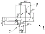
Fig. 9A to 9C show different openings 700 from the instrument housing wall GW, which can be used particularly preferably with the conceivable instrument socket 100 according to the first and second aspects of the invention and the conceivable instrument plug system 600.
It is particularly preferred to design the instrument receptacle 100 such that its contour corresponds to the contour of the opening 700, or at least partially follows the contour of the opening 700. All subsequent dimensional specifications also include deviations due to processing tolerances.
In fig. 9A to 9C, the openings 700 each have a circular contour with two parallel, straight sections opposite each other with respect to the circle center.
The circular contour of the respective opening 700 can extend here with a circular diameter of at least 10mm, 15mm, 20mm or 25 mm. Alternatively or additionally, the respective circular contour can extend with a circular diameter of at most 100mm, 90mm, 80mm, 70mm, 60mm, 50mm, 40mm or 30 mm. The circular profile particularly preferably has a circular diameter of 28.5 mm.
The straight sections 701 may be spaced apart from each other by a (horizontal) distance in the range of at least 10mm, 15mm, 20mm or 25 mm. Particularly preferably, the straight sections 701 are spaced apart from each other by 26 mm.
The opening 700 may also have further cutouts 705, which may be provided, for example, for fastening the ground terminal 251 and/or for additional locking or fastening of the instrument socket 100.
In fig. 9A, the further punch-out cuts 705 can be formed by two circular cuts spaced apart from one another. Preferably, the two circular incisions here have a distance in the range of at least 10mm, 15mm, 20mm or 25 mm. It is particularly preferred that the two circular incisions are spaced apart from each other by 14 mm.
The two circular cutouts may also each have a vertical distance from the center of the circular contour. The vertical distance may then have a range of at least 10mm, 15mm, 20mm or 25 mm. It is particularly preferred that the two circular cutouts have a vertical distance of 18mm from the center of the circular contour.
For the preferred sizing of the other die cuts 705 as shown in fig. 9B and 9C, see the length dimensions indicated in the figures.
The invention is not limited by the foregoing embodiments, but rather it is encompassed by the subject matter of the following claims. In particular, all features of the embodiments can be combined with each other and exchanged for each other in any way.
Claims (32)
1. An instrument receptacle (100) for detachably securing in an opening (700) of a motorized instrument, the instrument receptacle having:
-a socket body (110) having an outer wall (120) which extends at least partially along and further within a cylindrical shape (F), and a plug receiving cavity (150) which is surrounded by the outer wall (120) and has an insertion hole (151) for inserting a plug (500) in an insertion direction (E), from which the plug receiving cavity (150) extends;
-at least two electrical contacts (200,202,205) arranged within said cylindrical shape (F) and extending to electrically close a plug (500) inserted through said insertion hole (151), wherein one of said contacts (200,202,205) is a ground contact (205); and
-a ground terminal (251) electrically connected to the ground contact (205) and extending laterally in a direction outwardly from the outer wall (120) and substantially perpendicularly from the axis of rotational symmetry of the cylindrical shape (F).
2. The instrument receptacle (100) according to claim 1, wherein the receptacle body (110) has a circular contour with a circular diameter in the range of 10mm to 100mm, preferably viewed in the insertion direction (E), in a region in which the outer wall (120) extends along the cylindrical shape (F), and/or wherein the cylindrical shape (F) has a diameter in the range of 10mm to 100 mm.
3. The instrument receptacle (100) according to claim 1 or 2, wherein the receptacle body (110) or the outer wall (120) thereof has two first sections (101) within the cylindrical shape (F), preferably opposite with respect to the rotational symmetry axis and also preferably parallel and in particular straight, which are connected by at least one and preferably two second sections (102), preferably opposite with respect to the rotational symmetry axis and extending substantially along the cylindrical shape (F), wherein the first sections (101) and/or the second sections (102) are arranged evenly distributed around the receptacle body (110) or the cylindrical shape (F).
4. The instrument receptacle (100) of claim 3, wherein the ground terminal (251) extends from one of the second sections (102).
5. The instrument receptacle (100) according to one of the preceding claims, wherein the ground terminal (251) extends flat, preferably in a plane perpendicular to the rotational symmetry axis and/or in a plane perpendicular to the insertion direction (E).
6. The instrument receptacle (100) according to any one of the preceding claims, wherein the ground terminal (251) is connected with the ground contact (205) by a connection portion (252) to form a ground contact element (250), wherein the connection portion (252) extends longitudinally, preferably laterally, along the outer wall (120) and preferably substantially parallel to the rotational symmetry axis.
7. The instrument receptacle (100) according to one of the preceding claims, wherein the connection portion (252) extends along the second section (102) with the ground terminal (251) and/or wherein the ground terminal (251) is provided on a part of the outer wall (120), preferably on the second section (102), which part is formed in the form of a back recess (112) towards the rotational symmetry axis with respect to the cylindrical shape (F), wherein the back recess (112) preferably extends in a plane parallel to the rotational symmetry axis, wherein the connection portion (252) preferably extends along the back recess (112) and preferably also within the cylindrical shape (F).
8. The instrument receptacle (100) according to any one of the preceding claims, wherein the ground terminal (251) and the ground contact (205) are preferably constructed integrally with each other by the connecting portion (252), and/or wherein the contact (200,202,205) and preferably the ground contact element (250) are constructed in the form of a stamped bent piece.
9. The instrument receptacle (100) according to any one of the preceding claims, wherein the ground terminal (251) has at least one, preferably two ground terminal openings (253), a (geometric) center point of which preferably has a distance to the rotational symmetry axis in the range of 10mm to 50mm, wherein the two ground terminal openings (253) are preferably arranged mirror-symmetrically with respect to the ground terminal (251) and/or with respect to a radial direction of the rotational symmetry axis.
10. The instrument receptacle (100) according to any one of the preceding claims, wherein the portion extending along the cylindrical shape (F), preferably at least one of the second sections (102), extends over an angular range of at least 20 °, or at least 30 °, or at least 40 °, or at least 60 °, or at least 90 °, or at least 120 °, or at least 130 °, seen in the direction of the rotational symmetry axis.
11. The instrument receptacle (100) according to any one of the preceding claims, wherein the receptacle body (110) extends longitudinally along the rotational symmetry axis, preferably with a longitudinal extension in the range of 10mm to 100 mm.
12. The instrument receptacle (100) according to one of the preceding claims, further having a support (116) for bearing on an edge region of an opening (700) which at least partially receives the instrument receptacle (100), preferably the receptacle body (110), and preferably at least the rear side of the receptacle body (110), wherein the support (116) is preferably formed by a preferably annular projection (115) of the receptacle body (110) which surrounds at least in sections on the circumferential side on the outer wall (120) on the outer side, wherein the support (116) is preferably arranged on the front end of the receptacle body (110) as viewed in the insertion direction (E) and/or in the region of the insertion opening (151) and/or in a plane which delimits the insertion opening (151), and/or wherein the support (116) preferably extends in a plane which is perpendicular to the rotational axis of symmetry and/or in a plane which is perpendicular to the insertion direction (E) and/or in a plane which is perpendicular to the insertion axis (151) In the plane of the direction (E) and/or in the plane in which the ground terminal (251) also extends.
13. The instrument receptacle (100) according to any one of the preceding claims, wherein the receptacle body (110) has a bottom (152) which delimits the plug receiving chamber (150), preferably on a side opposite the insertion aperture (151).
14. The instrument receptacle (100) according to any one of the preceding claims, wherein the electrical contacts (200,202,205) extend in an insertion direction (E), preferably opposite the insertion direction (E), from the bottom (152) into the plug accommodating chamber (150), and wherein the electrical contacts (200,202,205) preferably project in towards the insertion apertures (151).
15. The instrument socket (100) according to one of the preceding claims, wherein the electrical contact (200,202,205) and/or the ground terminal (251) is detachably connected with the socket body (110), preferably is received or held in a through-hole (153) which connects the plug receiving chamber (150) with the rear side (160) of the socket body (110), preferably via the bottom (152), wherein the electrical contact (200,202,205) extends through its through-hole (153), preferably in or through the socket body (110), in particular via the bottom (152).
16. The instrument socket (100) according to one of the preceding claims, wherein the electrical contacts (200,202,205) each have a plug contact portion (220) for electrically conductively contacting a plug (500) inserted through the insertion opening (151) and at least one instrument connection portion (210) for connecting instrument-side electrical contacts (200,202,205), wherein the plug contact portion (220) preferably faces the plug receiving chamber (150) or projects into the plug receiving chamber, wherein the instrument connection portion (210) is preferably provided exposed at the rear side (160) or is accessible from the rear side (160), and/or wherein the instrument connection portion (210) is designed as a plug blade or a soldered lead.
17. The instrument receptacle (100) according to one of the preceding claims, wherein the electrical contacts (200,202,205) extend in a plane which preferably extends along or parallel to the rotational symmetry axis and/or the insertion direction (E), and/or wherein the electrical contacts (200,202,205) have an elongated I-shape or Y-shape or a curved L-shape or T-shape, wherein the plug contact portion (220) is provided on one end, the at least one instrument connection portion (210) being provided on the end of the respective electrical contact (200,202,205) which is opposite with respect to the plug contact portion (220), wherein the instrument connection portions (210) preferably extend away from one another in the opposite direction in the case of the T-shape and are clamped at an angle of less than 180 ° in the case of the Y-shape and preferably extend parallel to one another.
18. The instrument receptacle (100) according to one of the preceding claims, wherein the plug receptacle (150) has a substantially elongate and/or rectangular and/or asymmetrical, in particular rotationally asymmetrical, cross section, as seen in an insertion direction (E), wherein a longitudinal side of the plug receptacle (150) preferably faces the first section (101) and a narrow side of the plug receptacle (150) faces the second section (102), wherein the electrical contacts (200,202,205) are preferably arranged side by side, in particular in relation to the longitudinal direction of the plug receptacle (150), wherein the plug receptacle (150) preferably has at least one convex edge portion (154), which preferably also lies opposite the ground terminal (251) in relation to the plug receptacle (150).
19. The instrument receptacle (100) according to one of the preceding claims, wherein the plug receptacle (150) has at least one coding structure (155) which is designed to cooperate with a coding structure counterpart of a plug (500) inserted into the plug receptacle (150) in order to achieve a connection of the instrument receptacle (100) only with a suitable plug, wherein the coding structure (155) is preferably formed, in particular, in the form of a projection, preferably in a convex edge portion (154), and/or wherein the coding structure (155) extends longitudinally in the insertion direction (E) or in the direction of the rotational axis of symmetry.
20. The instrument receptacle (100) according to one of the preceding claims, further having at least one locking element (300), which is preferably arranged in the region of the outer wall (120) or extends along the cylindrical shape (F), wherein the locking element (300) is preferably movably, in particular rotatably, arranged, wherein the locking element (300) extends laterally outward away from the rotational symmetry axis and preferably has a locking projection (310) beyond the cylindrical shape (F) in order to preferably detachably retain the instrument receptacle (100) within one of the cylindrical shapes (F) or a portion of an opening (700) that follows the cross-sectional contour of the outer wall (120).
21. The instrument receptacle (100) according to claim 20, wherein the outer wall (120) has a pivot space (130) in the region of the locking member (300), which forms a free space (130) with respect to the cylindrical shape (F), preferably a free space (130) extending parallel to the rotational symmetry axis, to selectively accommodate a respective locking member (300) allowing its movement or its rotation in order to enable the removal of the mounted instrument receptacle (100) or the mounted receptacle body (110) from the opening (700).
22. The instrument receptacle (100) according to claim 20 or 21, wherein the instrument receptacle (100) has a plurality of locking elements (300) which are preferably arranged evenly distributed around the receptacle body (110), and preferably around the outer wall (120).
23. The instrument receptacle (100) according to one of the preceding claims, wherein the instrument receptacle (100) further has a plug-arresting lever (400) having a locking projection (430) which is movably arranged between a locking position, in which the locking projection projects radially into the plug-receiving chamber (150), preferably with respect to the rotational symmetry axis or with respect to an insertion direction (E), viewed in the insertion direction (E), and an unlocking position, in which the locking projection does not project into the plug-receiving chamber (150), viewed in the insertion direction (E).
24. The instrument receptacle (100) according to claim 23, wherein the locking projection (430) has a thrust ramp (431) extending obliquely with respect to the insertion direction (E) and preferably opposite thereto, so that the plug-arresting lever (400) is moved from the locking position into the unlocking position only when the plug (500) is inserted into the plug-receiving chamber (150).
25. The instrument receptacle (100) according to claim 23 or 24, wherein the plug stop lever (400) has a spring portion (420) with a fixing end for fixing the plug stop lever (400) with the receptacle body (110) or the outer wall (120) and a locking end spaced apart from or opposite the fixing end, which locking end has the locking projection (430) for rotating the plug stop lever (400) past the fixing end, wherein the plug stop lever (400) and in particular the spring portion (420) preferably extends from the fixing end toward the locking end, preferably substantially along the rotational symmetry axis, toward the insertion hole (151), and/or wherein the plug stop lever (400), preferably at least the spring portion (420), is preferably arranged on a plug of the outer wall (120) and preferably of one of the first part sections (101), the plug locking part is designed as a recess (113) with respect to the cylindrical shape (F) towards the rotational symmetry axis, so that the plug catch lever (400) is seated within the recess (113) in each rotational position, in particular in the locking position and the unlocking position.
26. The instrument receptacle (100) according to any one of claims 23 to 25, wherein the plug arresting bar (400) has a grip portion (410) which preferably extends from the locking end and also preferably extends opposite the insertion direction (E), preferably projects outside the receptacle body (110), to allow an operator to move the plug arresting bar (400) between the locked position and the unlocked position.
27. The instrument receptacle (100) according to one of claims 23 to 26, wherein the plug arresting bar (400), preferably the grip (410), has a stop (440) which is inclined in a locked position with respect to a bearing plane perpendicular to the rotational symmetry axis opposite to the insertion direction (E) in such a way that the stop (440) extends in the bearing plane in an unlocked position, wherein the bearing plane preferably corresponds to a plane defined by the insertion hole (151).
28. The instrument receptacle (100) according to one of the preceding claims, wherein the receptacle body (110) and preferably also the support (116) are manufactured from plastic, preferably integrally formed, preferably also in a multi-component injection molding process, wherein one component, preferably the support (116) or a part of the support (116), is preferably manufactured from an elastic sealing material.
29. An instrument receptacle (100) for detachably securing within an opening (700) of a motorized instrument, the instrument receptacle comprising:
-a socket body (110) having an outer wall (120) extending at least partially along and further within a cylindrical shape (F), and a plug receiving cavity (150) surrounded by the outer wall (120) and having an insertion aperture (151) for insertion of a plug (500) in an insertion direction (E), the plug receiving cavity (150) extending from the insertion aperture; and
-at least two electrical contacts (200,202,205) arranged within the cylindrical shape (F) and extending to be in electrically conductive contact with a plug (500) inserted via the insertion hole (151);
wherein the socket body (110) or an outer wall (120) thereof has two first sections (101) within the cylindrical shape (F) that are opposite, preferably parallel and straight, with respect to an axis of rotational symmetry of the cylindrical shape (F), which first sections are connected by at least two second sections (102) that are opposite with respect to the axis of rotational symmetry and extend substantially along the cylindrical shape (F).
30. An instrument plug (500) having a contour corresponding to the plug receiving cavity (150) of the instrument socket (100) according to one of the preceding claims for receiving the instrument plug (500) in the plug receiving cavity (150) for electrically conductive contacting of the contacts (200,202,205) of the instrument socket (100), wherein the instrument plug (500) has a locking structure (531) corresponding to a locking projection (430) of the plug stop lever (400) in order to detachably retain the instrument plug (500) in the plug receiving cavity (150) in the locking position of the plug stop lever (400).
31. The instrument plug (500) of claim 30 further having a coding structure counterpart corresponding to the coding structure (155).
32. An instrument insertion system, comprising:
the instrument receptacle (100) of any one of claims 1 to 29,
an instrument plug (500) corresponding to the instrument socket (100), preferably an instrument plug (500) according to claim 30 or 31, for electrically conductively contacting the contacts (200,202,205) of the instrument socket (100) by accommodating the instrument plug (500) in the plug-accommodating cavity (150).
Applications Claiming Priority (2)
| Application Number | Priority Date | Filing Date | Title |
|---|---|---|---|
| DE202018105641.7 | 2018-10-01 | ||
| DE202018105641.7U DE202018105641U1 (en) | 2018-10-01 | 2018-10-01 | Appliance socket, appliance plug and appliance plug system |
Publications (1)
| Publication Number | Publication Date |
|---|---|
| CN110970777A true CN110970777A (en) | 2020-04-07 |
Family
ID=68069634
Family Applications (1)
| Application Number | Title | Priority Date | Filing Date |
|---|---|---|---|
| CN201910935027.2A Pending CN110970777A (en) | 2018-10-01 | 2019-09-29 | Instrument socket, instrument plug and instrument plugging system |
Country Status (5)
| Country | Link |
|---|---|
| EP (1) | EP3633802B1 (en) |
| CN (1) | CN110970777A (en) |
| DE (1) | DE202018105641U1 (en) |
| PL (1) | PL3633802T3 (en) |
| SI (1) | SI3633802T1 (en) |
Families Citing this family (2)
| Publication number | Priority date | Publication date | Assignee | Title |
|---|---|---|---|---|
| JP7453067B2 (en) | 2020-06-05 | 2024-03-19 | 矢崎総業株式会社 | connector set |
| CN113328316B (en) * | 2021-04-25 | 2022-06-03 | 佛山照明智达电工科技有限公司 | Socket spot welding all-in-one |
Citations (6)
| Publication number | Priority date | Publication date | Assignee | Title |
|---|---|---|---|---|
| US3723942A (en) * | 1972-03-03 | 1973-03-27 | Arrow Hart Inc | Grounding clip electric receptacles |
| US5807125A (en) * | 1997-02-19 | 1998-09-15 | Molex Incorporated | System for mounting an electrical connector in a support structure |
| US20040077214A1 (en) * | 2001-12-17 | 2004-04-22 | James Turek | Electrical connection bulkhead header |
| US20060099841A1 (en) * | 2002-05-30 | 2006-05-11 | Heyco, Inc. | Connectors for under cabinet lighting |
| CN106663896A (en) * | 2014-09-03 | 2017-05-10 | 高准公司 | Connector with latch |
| CN107919579A (en) * | 2016-10-10 | 2018-04-17 | 鸿富锦精密电子(天津)有限公司 | The connection component of socket and the application socket |
Family Cites Families (6)
| Publication number | Priority date | Publication date | Assignee | Title |
|---|---|---|---|---|
| DE2725796C2 (en) * | 1977-06-08 | 1985-06-13 | M.A.N. Maschinenfabrik Augsburg-Nürnberg AG, 8000 München | Electrical outlet |
| AU668594B2 (en) * | 1992-11-13 | 1996-05-09 | Alcatel Components Limited | Electrical connector assembly |
| US7326063B1 (en) * | 2007-02-06 | 2008-02-05 | Tyco Electronics Corporation | Panel mount connector housing |
| JP4951465B2 (en) * | 2007-10-29 | 2012-06-13 | 第一電子工業株式会社 | Electrical connector |
| DE202010000547U1 (en) * | 2010-04-09 | 2010-06-10 | ABL SURSUM Bayerische Elektrozubehör GmbH & Co. KG | Electrical socket or coupling with lighting device |
| DE102017122649A1 (en) * | 2017-09-28 | 2019-03-28 | Unger Kabel-Konfektionstechnik GmbH | Appliance plug with locking system for the appliance box in case of incorrect installation, device connection system and electrical appliance |
-
2018
- 2018-10-01 DE DE202018105641.7U patent/DE202018105641U1/en active Active
-
2019
- 2019-09-26 SI SI201930220T patent/SI3633802T1/en unknown
- 2019-09-26 PL PL19199726.1T patent/PL3633802T3/en unknown
- 2019-09-26 EP EP19199726.1A patent/EP3633802B1/en active Active
- 2019-09-29 CN CN201910935027.2A patent/CN110970777A/en active Pending
Patent Citations (6)
| Publication number | Priority date | Publication date | Assignee | Title |
|---|---|---|---|---|
| US3723942A (en) * | 1972-03-03 | 1973-03-27 | Arrow Hart Inc | Grounding clip electric receptacles |
| US5807125A (en) * | 1997-02-19 | 1998-09-15 | Molex Incorporated | System for mounting an electrical connector in a support structure |
| US20040077214A1 (en) * | 2001-12-17 | 2004-04-22 | James Turek | Electrical connection bulkhead header |
| US20060099841A1 (en) * | 2002-05-30 | 2006-05-11 | Heyco, Inc. | Connectors for under cabinet lighting |
| CN106663896A (en) * | 2014-09-03 | 2017-05-10 | 高准公司 | Connector with latch |
| CN107919579A (en) * | 2016-10-10 | 2018-04-17 | 鸿富锦精密电子(天津)有限公司 | The connection component of socket and the application socket |
Also Published As
| Publication number | Publication date |
|---|---|
| PL3633802T3 (en) | 2022-07-18 |
| EP3633802B1 (en) | 2022-03-02 |
| SI3633802T1 (en) | 2022-06-30 |
| EP3633802A1 (en) | 2020-04-08 |
| DE202018105641U1 (en) | 2020-01-03 |
Similar Documents
| Publication | Publication Date | Title |
|---|---|---|
| KR101910283B1 (en) | Coaxial connector assembly | |
| US8956192B2 (en) | Finger protection for 90° header | |
| US9493083B1 (en) | Electrical plug adapter | |
| US7255587B2 (en) | Electric plug and electric plug socket | |
| CN107968297B (en) | Contact for a plug connector | |
| US9583875B2 (en) | Plug connector with two types of locking devices | |
| CN107925183B (en) | Plug-in connector | |
| CN111937245B (en) | Electrical connector, modular system and method for providing a connector | |
| KR20190028329A (en) | Intermediate adapter for attaching a connector unit to an appliance, and power supply kit | |
| KR20010092337A (en) | Device for the plug-in connection of a cable to a vehicle battery terminal | |
| US9640342B2 (en) | System comprising electronics housing and grounding contact assembly | |
| CN110970777A (en) | Instrument socket, instrument plug and instrument plugging system | |
| US20220037835A1 (en) | High-current electrical connector and electrical connector system | |
| JP2020518099A (en) | Assembly for connector member with contact insert and grounding element | |
| JP2001035565A (en) | Electrical connector for coaxial cable | |
| CN104617436A (en) | Socket-shaped housing, connector, and connector arrangement with cable support | |
| US3344390A (en) | Fluorescent tube socket | |
| JP5303348B2 (en) | Lock structure and electrical connector using the lock structure | |
| US20200227902A1 (en) | Direct coverplate | |
| US9397413B2 (en) | Neutral-ground subassembly for electric meter assembly | |
| EP2280456A1 (en) | Electrical connector having a dielectric insert for retaining an electrical contact | |
| CA2687009C (en) | Wiring device assembly with contact stabilizing structure | |
| CN114665326A (en) | First connector, second connector and connector combination | |
| US10714873B2 (en) | Plug with protective conductor bridge | |
| CN112038817A (en) | Electrical socket |
Legal Events
| Date | Code | Title | Description |
|---|---|---|---|
| PB01 | Publication | ||
| PB01 | Publication | ||
| SE01 | Entry into force of request for substantive examination | ||
| SE01 | Entry into force of request for substantive examination |