CN110940007A - Mobile household intelligent ecological system device - Google Patents
Mobile household intelligent ecological system device Download PDFInfo
- Publication number
- CN110940007A CN110940007A CN201911303083.0A CN201911303083A CN110940007A CN 110940007 A CN110940007 A CN 110940007A CN 201911303083 A CN201911303083 A CN 201911303083A CN 110940007 A CN110940007 A CN 110940007A
- Authority
- CN
- China
- Prior art keywords
- plate
- water tank
- base
- motor
- fixedly connected
- Prior art date
- Legal status (The legal status is an assumption and is not a legal conclusion. Google has not performed a legal analysis and makes no representation as to the accuracy of the status listed.)
- Pending
Links
Images


Classifications
-
- F—MECHANICAL ENGINEERING; LIGHTING; HEATING; WEAPONS; BLASTING
- F24—HEATING; RANGES; VENTILATING
- F24F—AIR-CONDITIONING; AIR-HUMIDIFICATION; VENTILATION; USE OF AIR CURRENTS FOR SCREENING
- F24F3/00—Air-conditioning systems in which conditioned primary air is supplied from one or more central stations to distributing units in the rooms or spaces where it may receive secondary treatment; Apparatus specially designed for such systems
- F24F3/12—Air-conditioning systems in which conditioned primary air is supplied from one or more central stations to distributing units in the rooms or spaces where it may receive secondary treatment; Apparatus specially designed for such systems characterised by the treatment of the air otherwise than by heating and cooling
- F24F3/16—Air-conditioning systems in which conditioned primary air is supplied from one or more central stations to distributing units in the rooms or spaces where it may receive secondary treatment; Apparatus specially designed for such systems characterised by the treatment of the air otherwise than by heating and cooling by purification, e.g. by filtering; by sterilisation; by ozonisation
-
- F—MECHANICAL ENGINEERING; LIGHTING; HEATING; WEAPONS; BLASTING
- F24—HEATING; RANGES; VENTILATING
- F24F—AIR-CONDITIONING; AIR-HUMIDIFICATION; VENTILATION; USE OF AIR CURRENTS FOR SCREENING
- F24F13/00—Details common to, or for air-conditioning, air-humidification, ventilation or use of air currents for screening
- F24F13/20—Casings or covers
-
- F—MECHANICAL ENGINEERING; LIGHTING; HEATING; WEAPONS; BLASTING
- F24—HEATING; RANGES; VENTILATING
- F24F—AIR-CONDITIONING; AIR-HUMIDIFICATION; VENTILATION; USE OF AIR CURRENTS FOR SCREENING
- F24F13/00—Details common to, or for air-conditioning, air-humidification, ventilation or use of air currents for screening
- F24F13/32—Supports for air-conditioning, air-humidification or ventilation units
-
- F—MECHANICAL ENGINEERING; LIGHTING; HEATING; WEAPONS; BLASTING
- F24—HEATING; RANGES; VENTILATING
- F24F—AIR-CONDITIONING; AIR-HUMIDIFICATION; VENTILATION; USE OF AIR CURRENTS FOR SCREENING
- F24F2221/00—Details or features not otherwise provided for
- F24F2221/12—Details or features not otherwise provided for transportable
- F24F2221/125—Details or features not otherwise provided for transportable mounted on wheels
Abstract
The invention discloses a mobile household intelligent ecosystem device, which comprises a water tank, a base, moving wheels and an electric appliance box, wherein the bottom end of the water tank is connected to the base, the water tank is arranged right above the base, the bottom end of the base is fixedly connected with a bottom plate, the moving wheels are fixedly arranged on the lower end face of the bottom plate, a sucker is further arranged below the bottom plate, the electric appliance box is arranged at the central position of the upper end face of the water tank, the electric appliance box is of a vertically-arranged rectangular plate-shaped structure, two sides of the electric appliance box are fixedly connected with limiting parts, the limiting parts are provided with four groups, a screen plate is arranged between two adjacent groups of the limiting parts, the screen plates are arranged in two groups and in parallel, meshes are arranged on the screen plates, and are. This portable intelligent ecosystem device of family, reasonable in design, convenient to use can satisfy people's user demand.
Description
Technical Field
The invention belongs to the technical field of intelligent home furnishing, and particularly relates to a mobile household intelligent ecosystem device.
Background
Due to rapid development of economy, great pollution is brought to the ecological large environment of people, and the life quality of people is directly influenced. In the face of increasingly worsened air environment, various household air purifier products are produced, the existing air purification treatment equipment almost adopts a purification means of filtering sucked air, the method has the defect of high operation cost, and although the method can have good adsorption treatment effect on various dust in the air, the method does not change the air quality of the household environment space qualitatively.
In the patent nos.: CN105066309B discloses an intelligent household ecosystem device, which is a brand new air optimization method for simulating natural ecological cycle, and adopts passive, active and open means to carry out all-around air optimization processing on living environment space, thereby essentially improving the air quality of the environment space. However, the invention still has some problems, such as the lack of a protection device, and the invention is not convenient to move, thereby failing to meet the use requirements of people.
Disclosure of Invention
The present invention is directed to a mobile home intelligent ecosystem apparatus, which solves the above problems.
In order to achieve the purpose, the invention provides the following technical scheme: the movable type household intelligent ecosystem device comprises a water tank, a base, movable wheels and an electric appliance box, wherein the bottom end of the water tank is connected with the base, the water tank is arranged right above the base, the bottom end of the base is fixedly connected with a bottom plate, the lower end surface of the bottom plate is fixedly provided with the movable wheels, a sucker is also arranged below the bottom plate, the electric appliance box is fixedly arranged at the central position of the upper end surface of the water tank and is of a vertically-arranged rectangular plate-shaped structure, two sides of the electric appliance box are fixedly connected with limiting parts, the limiting parts are provided with four groups, the limiting parts are arranged in parallel in pairs, a screen plate is arranged between every two adjacent limiting parts, the screen plates are arranged in parallel in pairs, meshes are arranged on the screen plates, the meshes are provided with multiple groups and are communicated with the, two groups of handles are arranged in parallel relatively;
the movable wheels are provided with four groups, an installation channel for installing balls is arranged between the base and the water tank, a cavity is arranged in the base, a first fixing piece is fixedly connected to the outer side of the bottom end of the water tank, a second fixing piece is fixedly connected to the outer side of the top end of the base, the first fixing piece and the second fixing piece are fixedly connected through an adjusting bolt, the first fixing piece is arranged right above the second fixing piece, a fixing device is fixedly installed on the bottom plate, the bottom end of the fixing device is connected with a push rod, and the bottom end of the push rod is fixedly connected with a sucker;
the fixing device comprises a box body, a second power supply is fixedly connected to one side of the box body, an accommodating space is formed in the box body, a push rod, a second motor, a partition plate, a threaded rod, a push plate and a moving block are respectively arranged in the box body, the partition plate is fixedly connected with the inner wall of the box body, and the second power supply is electrically connected with the second motor;
the utility model discloses a water tank, including cavity, base, water tank, pivot, first motor, pivot, first power, first motor, pivot, the cavity is inside to be equipped with first motor, pivot and first power respectively, first motor and first power electric connection, first motor bottom and cavity bottom inner wall fixed connection, first motor top is connected with the pivot, the one end that first motor was kept away from in the pivot passes base and water tank bottom fixed connection.
Preferably, fixing device, second power, push rod and sucking disc all are equipped with the multiunit, fixing device quantity is the same with second power quantity, the push rod top is passed the bottom plate and is located the box body in, the push rod bottom mounting is provided with the sucking disc, sucking disc quantity is the same with push rod quantity.
Preferably, the base top is located the pivot position and inlays and install the bearing, the bearing is fixed to be set up in the pivot, the terminal surface is located second power position and is equipped with the hole of charging under the bottom plate, charges downthehole from down and install the rubber buffer.
Preferably, the slide that is used for placing the ball is all offered with the water tank bottom in base top, the slide is the loop configuration, the slide is parallel relatively and is equipped with two sets ofly, the ball uses the pivot as centre of a circle annular array multiunit.
Preferably, one side of the limiting part close to the screen plate is provided with a limiting groove, a plurality of groups of limiting grooves are arranged in parallel relatively, the two sides of the screen plate are located at the position of the limiting groove and provided with a clamping groove, the limiting groove is matched with the clamping groove, the plurality of groups of clamping grooves are also arranged in parallel relatively, and the number of the limiting grooves is the same as that of the clamping grooves.
Preferably, the box body is internally divided into an upper group of relatively independent installation spaces and a lower group of relatively independent installation spaces through a partition plate, the two groups of installation spaces are respectively a first installation cavity and a second installation cavity, and the second installation cavity is arranged right above the first installation cavity.
Preferably, the second motor is arranged in the second mounting cavity, the push plate, the threaded rod, the push rod and the moving block are all arranged in the first mounting cavity, the bottom end of the second motor is fixedly connected with the upper end face of the partition plate, the top end of the threaded rod penetrates through the partition plate to be connected with the second motor, and the bottom end of the threaded rod penetrates through the push plate to be rotatably connected with the upper end face of the bottom plate.
Preferably, the top end of the push rod is fixedly connected with the lower end face of the push plate, the push rod and the push plate are arranged in a right-angle structure, through holes are formed in the positions, where the push rod is located, of the bottom plate, multiple groups of through holes are formed, and the number of the through holes is the same as that of the push rods.
Preferably, moving blocks are fixedly connected to two ends of the push plate, sliding grooves are formed in the positions, where the moving blocks are located, of the inner walls of two ends of the box body, the moving blocks are arranged in the sliding grooves, the push plate is connected with the box body in a sliding mode, and the push plate is in threaded fit with the threaded rod.
Preferably, the water tank comprises a tank body and a cover body matched with the tank body, the electrical appliance box is mounted on the cover body, the tank body is provided with a water containing cavity, the water containing cavity is formed by being concavely arranged from the top surface of the tank body, and the cover body is used for covering an opening of the water containing cavity; the box is equipped with two driving motor, installs respectively in the driving gear of two driving motor's output shaft, and the both ends that the lid kept away from each other all are equipped with the rack, and the rack slides with the box and sets up, and two driving motor's gear respectively with the rack toothing at lid both ends.
The invention has the technical effects and advantages that: the mobile household intelligent ecosystem device is characterized in that two groups of screen plates are inserted between two adjacent groups of limiting parts from top to bottom, so that the two groups of screen plates are arranged in parallel relatively, one side of each screen plate, which is far away from a handle, is in contact with two sides of an electric appliance box, so that the electric appliance box can be protected, sundries are prevented from entering the electric appliance box, the problem that the device is lack of a protective device is solved, when the screen plates need to be taken out, the handle is held to pull the screen plates from bottom to top, the number of limiting grooves is equal to that of clamping grooves, so that the screen plates can be conveniently taken out of the two groups of limiting parts, through the design of the limiting parts and the limiting grooves, the screen plates are convenient to disassemble and assemble, the device is more flexible to use, a sucker is in contact with the ground, so that the stability of the assembling machine can, the base is passed to the one end that first motor was kept away from in the pivot and water tank bottom fixed connection, thereby make the device can be according to the orientation of user demand adjustment water tank, first mounting, the second mounting is fixed the setting respectively at the water tank, on the base, thereby be convenient for fix the position of water tank, the second motor can drive the threaded rod and rotate, screw-thread fit through threaded rod and push pedal, the push pedal can promote the push rod downwards, and then drive the sucking disc and do reciprocating motion from top to bottom, thereby reach the mesh of injecing the device position, the rubber buffer can avoid debris and water stain to enter into the charging hole, thereby can protect the second power in the charging hole, the design of through-hole, the installation of the push rod of being convenient for, this portable family intelligence ecosystem device, and reasonable design, high durability and convenient use, can satisfy people's user demand.
Drawings
FIG. 1 is a schematic structural view of the present invention;
FIG. 2 is a side view of the base of the present invention;
FIG. 3 is a schematic view of the internal structure of the base of the present invention;
FIG. 4 is a schematic view of the internal structure of the case according to the present invention;
FIG. 5 is an enlarged view taken at A of FIG. 4 in accordance with the present invention;
FIG. 6 is an enlarged view of the invention at B in FIG. 1;
fig. 7 is a schematic structural view of a water tank of the present invention.
In the figure: the water tank, the first fixed part, the second fixed part, the base 4, the movable wheel 5, the fixed device 6, the bottom plate 7, the adjusting bolt 8, the sucking disc 9, the rotating shaft 10, the push rod 11, the ball 12, the installation channel 13, the cavity 14, the first motor 15, the bearing 16, the first power supply 17, the slideway 18, the second power supply 19, the rubber stopper 20, the electrical box 21, the limiting piece 22, the limiting groove 23, the net plate 24, the handle 25, the mesh 26, the box 27, the second motor 28, the partition 29, the slideway 30, the first installation cavity 31, the through hole 32, the threaded rod 33, the push plate 34, the movable block 35, the second installation cavity 36, the box 37, the cover 38, the water containing cavity 39, the driving gear 40, the rack 41 and the sealing ring 42.
Detailed Description
The technical solutions in the embodiments of the present invention will be clearly and completely described below with reference to the drawings in the embodiments of the present invention, and it is obvious that the described embodiments are only a part of the embodiments of the present invention, and not all of the embodiments. All other embodiments, which can be derived by a person skilled in the art from the embodiments given herein without making any creative effort, shall fall within the protection scope of the present invention.
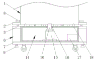
The invention provides a mobile household intelligent ecosystem device as shown in figures 1-7, which comprises a water tank 1, a base 4, a mobile wheel 5 and an electrical appliance box 21, wherein the bottom end of the water tank 1 is connected to the base 4, the water tank 1 is arranged right above the base 4, the bottom end of the base 4 is fixedly connected with a bottom plate 7, and the mobile wheel 5 is rotatably arranged at the lower end of the bottom plate 7. A sucking disc 9 is further arranged below the bottom plate 7, and an electric appliance box 21 is fixed at the center of the upper end face of the water tank 1.
The electric appliance box 21 is a vertically placed rectangular plate-shaped structure, the limiting parts 22 are fixedly connected to two sides of the electric appliance box 21, the limiting parts 22 are four groups, two groups of limiting parts 22 are arranged on one side of the electric appliance box 21, a net plate 24 is arranged between the two adjacent groups of limiting parts 22, and the net plate 24 is arranged in two groups and in parallel.
The movable wheels 5 are provided with four groups, an installation channel 13 for installing rolling balls 12 is arranged between the base 4 and the water tank 1, and a cavity 14 is arranged inside the base 4. The water tank comprises a water tank 1, a first fixing piece 2 fixedly connected to the outer side of the bottom end of the water tank 1, a second fixing piece 3 fixedly connected to the outer side of the top end of a base 4, the first fixing piece 2 and the second fixing piece 3 are fixedly connected through an adjusting bolt 8, and the first fixing piece 2 is arranged right above the second fixing piece 3.
The bottom plate 7 is fixedly provided with a fixing device 6, the bottom end of the fixing device 6 is connected with a push rod 11, a sucker 9 is arranged at the bottom end of the push rod 11, and the sucker 9 is used for sucking the ground, so that the stability of the assembling machine can be improved. The suction cup 9 can be made of silicon rubber, polyurethane and the like, the suction cup 9 made of the silicon rubber is very suitable for holding a product with a rough surface, and the suction cup made of the polyurethane is very durable. In addition, in actual production, if oil resistance is required for the sucker, materials such as polyurethane, nitrile rubber or vinyl-containing polymers can be considered for manufacturing the sucker, and in general, in order to avoid scratching the surface of the product, the material of the sucker with the bellows made of nitrile rubber or silicon rubber is preferably selected to be made of nitrile rubber, so that the sucker has high anti-pulling performance.
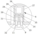
The fixing device 6 comprises a box body 27, a second power supply 19 is fixedly connected to one side of the box body 27, an accommodating space is formed inside the box body 27, a push rod 11, a second motor 28, a partition plate 29, a threaded rod 33, a push plate 34 and a moving block 35 are respectively arranged inside the box body 27, the partition plate 29 is fixedly connected with the inner wall of the box body 27, the second power supply 19 is electrically connected with the second motor 28, and the plane where the partition plate 29 is located is parallel to the plane where the bottom plate 7 is located.
The cavity 14 is internally provided with a first motor 15, a rotating shaft 10 and a first power supply 17 respectively, the first motor 15 is electrically connected with the first power supply 17, and the bottom end of the first motor 15 is fixedly connected with the inner wall of the bottom end of the cavity 14. The output shaft of first motor 15 is connected with pivot 10, the one end that first motor 15 was kept away from in pivot 10 passes base 4 and 1 bottom fixed connection of water tank to make the device can be according to the orientation of user demand adjustment water tank 1.
Specifically, first mounting 2 and second mounting 3 parallel arrangement, first mounting 2, second mounting 3 are the rectangular frame structure, first mounting 2, second mounting 3 are fixed the setting respectively on water tank 1, on base 4 to be convenient for fix the position of water tank 1.
Specifically, the base 4 is a cuboid structure, the bottom plate 7 is a rectangular plate-shaped structure, and a plane where the bottom plate 7 is located, a plane where the first fixing member 2 is located, and a plane where the second fixing member 3 is located are parallel. The first fixing piece 2 is in threaded connection with the adjusting bolt 8, and the bottom end of the adjusting bolt 8 penetrates through the first fixing piece 2 to be in threaded connection with the second fixing piece 3.
Specifically, fixing device 6, second power 19, push rod 11 and sucking disc 9 all are equipped with the multiunit, 6 quantity of fixing device is the same with 19 quantity of second power, bottom plate 7 is passed on the top of push rod 11 and is located in box body 27, 9 quantity of sucking discs are the same with 11 quantity of push rod, and second motor 28 can drive threaded rod 33 and rotate, and via the screw-thread fit of threaded rod 33 with push pedal 34, push pedal 34 can push rod 11 downwards, and then drives sucking disc 9 and do reciprocating motion from top to bottom to reach the mesh of prescribing a limit to the device position.
Specifically, 4 tops of base are located pivot 10 place positions and inlay and install bearing 16, bearing 16 is fixed to be set up in pivot 10, bottom plate 7 lower extreme terminal surface is located 19 places positions of second power and is equipped with the hole of charging, bottom plate 7 installs the rubber buffer 20 that is used for blockking up the hole of charging, and rubber buffer 20 can avoid debris and water stain to enter into the hole of charging to can protect downthehole second power 19 of charging.
Specifically, slide 18 that is used for placing rolling ball 12 is all offered with 1 bottom of water tank on the 4 tops of base, slide 18 is the circle annular structure, slide 18's quantity is two sets of and parallel arrangement, ball 12 uses pivot 10 to set up as centre of a circle annular array. In slide 18 was located to ball 12, ball 12 was the metal material, through ball 12's design to be convenient for water tank 1 follows pivot 10 and rotates, thereby be convenient for water tank 1 adjustment orientation.
Specifically, one side that locating part 22 is close to otter board 24 is equipped with spacing groove 23, the quantity of spacing groove 23 is multiunit and parallel arrangement, 24 both sides of otter board are located spacing groove 23 position and have seted up the draw-in groove, spacing groove 23 and draw-in groove looks adaptation, and the quantity of draw-in groove also is multiunit and parallel arrangement, spacing groove 23 quantity is the same with draw-in groove quantity to be convenient for take out otter board 24 from two sets of locating parts 22, in otter board 24 can avoid debris to enter into electrical apparatus box 21, thereby reach the purpose of protecting electrical apparatus box 21.
Specifically, box body 27 is inside to be separated for upper and lower two sets of relatively independent installation space via baffle 29, and two sets of installation space are first installation cavity 31, second installation cavity 36 respectively, second installation cavity 36 locates directly over first installation cavity 31, and then the installation of the second motor 28 of being convenient for, and the second motor 28 of being convenient for drives threaded rod 33 and moves.
Specifically, the second motor 28 is arranged in a second mounting cavity 36, the push plate 34, the threaded rod 33, the push rod 11 and the moving block 35 are all arranged in a first mounting cavity 31, the bottom end of the second motor 28 is fixedly connected with the upper end face of the partition plate 29, the top end of the threaded rod 33 penetrates through the output shaft of the partition plate 29 and the second motor 28, the bottom end of the threaded rod 33 penetrates through the push plate 34 to be rotatably connected with the upper end face of the bottom plate 7, the position, where the threaded rod 33 is located, of the bottom plate 7 is also provided with the bearing 16 in an embedded mode, the bearing 16 is fixedly arranged on the outer side of the threaded rod 33, so that the threaded rod 33 can rotate on the bottom plate.
Specifically, terminal surface fixed connection under push rod 11 top and the push pedal 34, set up perpendicularly between push rod 11 and the push pedal 34, it has seted up through-hole 32 to lie in push rod 11 position on the bottom plate 7, through-hole 32 is equipped with the multiunit, through-hole 32 quantity is the same with push rod 11 quantity, and the installation of push rod 11 is convenient for to the design of through-hole 32.
Specifically, both ends of the push plate 34 are fixedly connected with moving blocks 35, the inner walls of both ends of the box body 27 at the positions where the moving blocks 35 are located are provided with sliding grooves 30, the moving blocks 35 are arranged in the sliding grooves 30, the push plate 34 is slidably connected with the box body 27, and the push plate 34 is in threaded fit with the threaded rod 33.
Specifically, this portable intelligent ecosystem device of family, at first insert two sets of otter boards 24 from the top between two adjacent sets of locating parts 22, make two sets of otter boards 24 parallel arrangement relatively, and otter board 24 keeps away from one side of handle 25 and electrical apparatus case 21 both sides contact, when needs take out otter board 24, hold handle 25 with otter board 24 from up pulling down can.
Can remove the device to suitable position through removing wheel 5, then start to be located box body 27 in second motor 28, second motor 28 can drive threaded rod 33 and rotate, through the screw-thread fit of threaded rod 33 and push pedal 34, push pedal 34 can push down push rod 11 in through-hole 32, and then drives sucking disc 9 and do reciprocating up and down.
When the push plate 34 moves downwards, the push plate 34 moves in the sliding groove 30 through the design that the moving block 35 is matched with the sliding groove 30 until the suction cup 9 abuts against the bottom surface and sucks the ground, so that the purpose of limiting the position of the device is achieved. When the orientation of the device needs to be adjusted, the motor 15 is started, the rack 1 is driven to rotate on the base 4 through the rotating shaft 10, and after the orientation of the water tank 1 is adjusted, the adjusting bolt 8 on the first fixing piece 2 is screwed down, so that the adjusting bolt 8 is in threaded connection with the second fixing piece 3, and the purpose of fixing the position of the device is achieved.
When needs charge to second power 19, then take off the rubber buffer 20 can, after second power 19 charges, follow rubber buffer 20 again from up install in the charging hole that is located second power 19 bottom can, this portable family intelligence ecosystem device, reasonable in design, convenient to use can satisfy people's user demand.
The water tank 1 comprises a tank body 37 and a cover body 38 matched with the tank body 37 for use, the electrical box 21 is installed and fixed on the top end of the cover body 38, the tank body 37 is provided with a water containing cavity 39, the water containing cavity 39 is formed by the concave arrangement of the top surface of the tank body 37, and the cover body 38 is used for covering the opening of the water containing cavity 39.
Two driving motors and driving gears 40 respectively mounted on output shafts of the two driving motors are mounted on the box body 37, the driving motors are used for driving the driving gears 40 to rotate, racks 41 are fixedly connected to two ends, far away from each other, of the cover body 38, the racks 41 are arranged in a sliding manner with the box body 37, and gears 40 of the two driving motors are respectively meshed with the racks 41 at two ends of the cover body 38.
When the water in the water tank 1 needs to be replaced, the driving motor drives the driving gear 40 to rotate, the rotating driving gear 40 drives the rack 41 to slide relative to the tank body 37, the sliding rack 41 and the cover body 38 move towards the direction away from the tank body 37, so that the cover body 38 opens the water containing cavity 39, then the water in the water containing cavity 39 can be discharged or water can be added into the water containing cavity 39, and then the driving motor drives the cover body 38 to re-cover the opening of the water containing cavity 39 through the driving gear 40 and the rack 41.
Preferably, the box body 37 is provided with an annular blind groove surrounding the opening of the water containing cavity 39, the box body 37 is provided with a sealing ring 42 positioned in the annular blind groove, the sealing ring 42 protrudes out of the top surface of the box body 37 and abuts against the cover body 38, and the sealing ring 42 is utilized to seal the gap between the box body 37 and the cover body 38, so as to prevent the water in the water containing cavity 39 from leaking through the gap between the box body and the cover body.
The rear motor controller is installed on the base 4 and electrically connected with the two driving motors, and the motor controller controls the two driving motors to synchronously start or stop, so that the racks 41 at the two ends of the cover body 38 can synchronously lift, and the cover body 38 is prevented from being inclined in the moving process due to the fact that the two driving motors are asynchronous.
Finally, it should be noted that: although the present invention has been described in detail with reference to the foregoing embodiments, it will be apparent to those skilled in the art that modifications may be made to the embodiments or portions thereof without departing from the spirit and scope of the invention.
Claims (10)
1. Portable intelligent ecosystem device of family, including water tank (1), base (4), removal wheel (5) and electrical apparatus case (21), its characterized in that: the bottom end of the water tank (1) is connected to the base (4), the water tank (1) is arranged right above the base (4), the bottom end of the base (4) is fixedly connected with a bottom plate (7), the movable wheel (5) is rotatably arranged at the lower end of the bottom plate (7), and a sucker (9) is further arranged below the bottom plate (7);
the electric appliance box (21) is arranged at the center of the upper end face of the water tank (1), the electric appliance box (21) is of a vertically placed rectangular plate-shaped structure, and two sides of the electric appliance box (21) are fixedly connected with limiting pieces (22); four groups of limiting pieces (22) are arranged, a screen plate (24) is arranged between two adjacent groups of limiting pieces (22), and the screen plates (24) are arranged in two groups and are parallel;
the net plate (24) is provided with meshes (26), the meshes (26) are provided with a plurality of groups, the meshes (26) are communicated with the inside of the electric appliance box (21), one side of the net plate (24) far away from the electric appliance box (21) is fixedly connected with handles (25), and the handles (25) of the two groups of net plates (24) are arranged in parallel;
the four groups of moving wheels (5) are arranged, an installation channel (13) for installing rolling balls (12) is arranged between the base (4) and the water tank (1), a cavity (14) is arranged inside the base (4), a first fixing piece (2) is fixedly connected to the outer side of the bottom end of the water tank (1), a second fixing piece (3) is fixedly connected to the outer side of the top end of the base (4), the first fixing piece (2) and the second fixing piece (3) are fixedly connected through an adjusting bolt (8), and the first fixing piece (2) is arranged right above the second fixing piece (3);
a fixing device (6) is fixedly arranged on the bottom plate (7), the bottom end of the fixing device (6) is connected with a push rod (11), and a sucker (9) is arranged on the bottom end of the push rod (11);
the fixing device (6) comprises a box body (27), a second power supply (19) is fixedly connected to one side of the box body (27), an accommodating space is formed in the box body (27), a push rod (11), a second motor (28), a partition plate (29), a threaded rod (33), a push plate (34) and a moving block (35) are respectively arranged in the box body (27), the partition plate (29) is fixedly connected with the inner wall of the box body (27), and the second power supply (19) is electrically connected with the second motor (28);
the utility model discloses a water tank, including cavity (14), first motor (15), pivot (10) and first power (17) are inside to be equipped with respectively, first motor (15) and first power (17) electric connection, first motor (15) bottom and cavity (14) bottom inner wall fixed connection, the output shaft of first motor (15) has pivot (10), base (4) and water tank (1) bottom fixed connection are passed to the one end that first motor (15) were kept away from in pivot (10).
2. A mobile home smart ecosystem apparatus according to claim 1, wherein: fixing device (6), second power (19), push rod (11) and sucking disc (9) all are equipped with the multiunit, fixing device (6) quantity is the same with second power (19) quantity, push rod (11) top is passed bottom plate (7) and is located in box body (27), sucking disc (9) quantity is the same with push rod (11) quantity.
3. A mobile home smart ecosystem apparatus according to claim 1, wherein: base (4) top is located pivot (10) position and inlays and install bearing (16), bearing (16) cover is established in the pivot (10) outside, bottom plate (7) lower extreme position in second power (19) position is equipped with the hole of charging, bottom plate (7) are equipped with rubber buffer (20) that are used for blockking up the hole of charging.
4. A mobile home smart ecosystem apparatus according to claim 1, wherein: slide (18) that are used for holding ball (12) are all offered with water tank (1) bottom on base (4) top, slide (18) are the circular ring shape structure, slide (18) are two sets of and parallel arrangement, ball (12) use pivot (10) to be the annular array setting as the centre of a circle.
5. A mobile home smart ecosystem apparatus according to claim 1, wherein: one side that locating part (22) are close to otter board (24) is equipped with spacing groove (23), spacing groove (23) are multiunit and parallel arrangement, the draw-in groove has been seted up to otter board (24) both sides position in spacing groove (23), spacing groove (23) and draw-in groove looks adaptation, draw-in groove are multiunit and parallel arrangement, spacing groove (23) quantity is the same with draw-in groove quantity.
6. A mobile home smart ecosystem apparatus according to claim 1, wherein: the box body (27) is internally divided into an upper group of relatively independent installation spaces and a lower group of relatively independent installation spaces through a partition plate (29), the two groups of installation spaces are respectively a first installation cavity (31) and a second installation cavity (36), and the second installation cavity (36) is arranged right above the first installation cavity (31).
7. The mobile home smart ecosystem apparatus of claim 6, wherein: the second motor (28) is arranged in a second mounting cavity (36), the push plate (34), the threaded rod (33), the push rod (11) and the moving block (35) are all arranged in the first mounting cavity (31), the bottom end of the second motor (28) is fixedly connected with the upper end face of the partition plate (29), the top end of the threaded rod (33) penetrates through an output shaft of the partition plate (29) and the second motor (28), and the bottom end of the threaded rod (33) penetrates through the push plate (34) to be rotatably connected with the upper end face of the bottom plate (7).
8. A mobile home smart ecosystem apparatus according to claim 1, wherein: the push rod (11) top end and push pedal (34) lower extreme face fixed connection, push rod (11) and push pedal (34) perpendicular setting, through-hole (32) have been seted up to the position that lies in push rod (11) on bottom plate (7), through-hole (32) are equipped with the multiunit, through-hole (32) quantity is the same with push rod (11) quantity.
9. A mobile home smart ecosystem apparatus according to claim 1, wherein: the improved structure is characterized in that moving blocks (35) are fixedly connected to two ends of the push plate (34), sliding grooves (30) are formed in positions, where the moving blocks (35) are located, of inner walls of two ends of the box body (27), the moving blocks (35) are arranged in the sliding grooves (30), the push plate (34) is connected with the box body (27) in a sliding mode, and the push plate (34) is in threaded fit with the threaded rod (33).
10. A mobile home smart ecosystem apparatus according to claim 1, wherein: the water tank (1) comprises a tank body (37) and a cover body (38) matched with the tank body (37), the electric appliance box (21) is installed on the cover body (38), the tank body (37) is provided with a water containing cavity (39), the water containing cavity (39) is formed by recessing the top surface of the tank body (37), and the cover body (38) is used for covering an opening of the water containing cavity (39); the box body (37) is provided with two driving motors and driving gears (40) which are respectively arranged on output shafts of the two driving motors, racks (41) are respectively arranged at two ends, far away from each other, of the cover body (38), the racks (41) are arranged with the box body (37) in a sliding mode, and gears (40) of the two driving motors are respectively meshed with the racks (41) at two ends of the cover body (38).
Priority Applications (1)
| Application Number | Priority Date | Filing Date | Title |
|---|---|---|---|
| CN201911303083.0A CN110940007A (en) | 2019-12-17 | 2019-12-17 | Mobile household intelligent ecological system device |
Applications Claiming Priority (1)
| Application Number | Priority Date | Filing Date | Title |
|---|---|---|---|
| CN201911303083.0A CN110940007A (en) | 2019-12-17 | 2019-12-17 | Mobile household intelligent ecological system device |
Publications (1)
| Publication Number | Publication Date |
|---|---|
| CN110940007A true CN110940007A (en) | 2020-03-31 |
Family
ID=69911923
Family Applications (1)
| Application Number | Title | Priority Date | Filing Date |
|---|---|---|---|
| CN201911303083.0A Pending CN110940007A (en) | 2019-12-17 | 2019-12-17 | Mobile household intelligent ecological system device |
Country Status (1)
| Country | Link |
|---|---|
| CN (1) | CN110940007A (en) |
Cited By (2)
| Publication number | Priority date | Publication date | Assignee | Title |
|---|---|---|---|---|
| CN112191008A (en) * | 2020-11-04 | 2021-01-08 | 胡建红 | Efficient biological medicine sewage treatment plant |
| CN115083238A (en) * | 2022-05-14 | 2022-09-20 | 郑州科技学院 | Accounting teaching device combining digital model and solid model |
Citations (16)
| Publication number | Priority date | Publication date | Assignee | Title |
|---|---|---|---|---|
| JP2001201079A (en) * | 2000-01-21 | 2001-07-27 | Matsushita Refrig Co Ltd | Air conditioner |
| CN204764191U (en) * | 2015-06-11 | 2015-11-18 | 江苏金牌厨柜有限公司 | Liftable kitchen operation platform |
| CN105066309A (en) * | 2015-09-16 | 2015-11-18 | 陈汀若 | Intelligent household ecosystem device |
| CN205090575U (en) * | 2015-09-11 | 2016-03-16 | 珠海格力电器股份有限公司 | Air conditioning equipment and top cap elevating gear thereof |
| US20170023265A1 (en) * | 2013-07-30 | 2017-01-26 | Seoul Viosys Co., Ltd. | Air conditioner having air purifying module |
| CN207467163U (en) * | 2017-11-23 | 2018-06-08 | 北京鸿仪四方辐射技术股份有限公司 | For the babinet of Safety Irradiation |
| CN109084391A (en) * | 2018-09-09 | 2018-12-25 | 肇庆高新区黑阳科技有限公司 | It is a kind of except haze dehumidifying antibacterial central fresh air system |
| CN109217540A (en) * | 2018-11-02 | 2019-01-15 | 深圳市太美亚电子科技有限公司 | A kind of electric tool brushless motor radiator |
| CN109824224A (en) * | 2019-03-15 | 2019-05-31 | 苏州耀水源环境科技有限公司 | A kind of Treatment of Sludge device convenient for closing fermentation |
| CN209234412U (en) * | 2018-12-10 | 2019-08-13 | 杨海军 | Intelligent afforestation device |
| KR102014045B1 (en) * | 2019-02-26 | 2019-08-28 | 김현일 | A Stand system decreased a fine dust of four seasons for air purification plants |
| CN209459180U (en) * | 2018-12-20 | 2019-10-01 | 珠海格力电器股份有限公司 | A kind of panel ejecting mechanism, air conditioner indoor unit and air conditioner |
| CN209525621U (en) * | 2019-03-26 | 2019-10-22 | 江西工程学院 | A kind of computer high-effective dust-removing Destaticizing device |
| CN209561938U (en) * | 2019-03-29 | 2019-10-29 | 江苏常明电力设备有限公司 | A kind of automatic lifting type distribution box of shell |
| KR20190128886A (en) * | 2018-05-09 | 2019-11-19 | 이경석 | Water layer type cyclone air purifier |
| CN209661535U (en) * | 2019-01-29 | 2019-11-22 | 上海牧言室内装饰工程有限公司 | A kind of Multifunctional domestic device |
-
2019
- 2019-12-17 CN CN201911303083.0A patent/CN110940007A/en active Pending
Patent Citations (16)
| Publication number | Priority date | Publication date | Assignee | Title |
|---|---|---|---|---|
| JP2001201079A (en) * | 2000-01-21 | 2001-07-27 | Matsushita Refrig Co Ltd | Air conditioner |
| US20170023265A1 (en) * | 2013-07-30 | 2017-01-26 | Seoul Viosys Co., Ltd. | Air conditioner having air purifying module |
| CN204764191U (en) * | 2015-06-11 | 2015-11-18 | 江苏金牌厨柜有限公司 | Liftable kitchen operation platform |
| CN205090575U (en) * | 2015-09-11 | 2016-03-16 | 珠海格力电器股份有限公司 | Air conditioning equipment and top cap elevating gear thereof |
| CN105066309A (en) * | 2015-09-16 | 2015-11-18 | 陈汀若 | Intelligent household ecosystem device |
| CN207467163U (en) * | 2017-11-23 | 2018-06-08 | 北京鸿仪四方辐射技术股份有限公司 | For the babinet of Safety Irradiation |
| KR20190128886A (en) * | 2018-05-09 | 2019-11-19 | 이경석 | Water layer type cyclone air purifier |
| CN109084391A (en) * | 2018-09-09 | 2018-12-25 | 肇庆高新区黑阳科技有限公司 | It is a kind of except haze dehumidifying antibacterial central fresh air system |
| CN109217540A (en) * | 2018-11-02 | 2019-01-15 | 深圳市太美亚电子科技有限公司 | A kind of electric tool brushless motor radiator |
| CN209234412U (en) * | 2018-12-10 | 2019-08-13 | 杨海军 | Intelligent afforestation device |
| CN209459180U (en) * | 2018-12-20 | 2019-10-01 | 珠海格力电器股份有限公司 | A kind of panel ejecting mechanism, air conditioner indoor unit and air conditioner |
| CN209661535U (en) * | 2019-01-29 | 2019-11-22 | 上海牧言室内装饰工程有限公司 | A kind of Multifunctional domestic device |
| KR102014045B1 (en) * | 2019-02-26 | 2019-08-28 | 김현일 | A Stand system decreased a fine dust of four seasons for air purification plants |
| CN109824224A (en) * | 2019-03-15 | 2019-05-31 | 苏州耀水源环境科技有限公司 | A kind of Treatment of Sludge device convenient for closing fermentation |
| CN209525621U (en) * | 2019-03-26 | 2019-10-22 | 江西工程学院 | A kind of computer high-effective dust-removing Destaticizing device |
| CN209561938U (en) * | 2019-03-29 | 2019-10-29 | 江苏常明电力设备有限公司 | A kind of automatic lifting type distribution box of shell |
Cited By (2)
| Publication number | Priority date | Publication date | Assignee | Title |
|---|---|---|---|---|
| CN112191008A (en) * | 2020-11-04 | 2021-01-08 | 胡建红 | Efficient biological medicine sewage treatment plant |
| CN115083238A (en) * | 2022-05-14 | 2022-09-20 | 郑州科技学院 | Accounting teaching device combining digital model and solid model |
Similar Documents
| Publication | Publication Date | Title |
|---|---|---|
| CN110940007A (en) | Mobile household intelligent ecological system device | |
| CN203154978U (en) | Woodworking single-unit dust removal equipment | |
| CN109256690A (en) | A kind of dustproof electric cabinet | |
| CN111408202A (en) | Dust cover for gearbox | |
| CN208890126U (en) | A kind of dustproof electric cabinet | |
| CN219513572U (en) | Automatic change control switch board | |
| CN210246396U (en) | Electric power information monitoring device | |
| CN204306765U (en) | Powered brush brush car | |
| CN209331936U (en) | Electric cleaner | |
| CN204767236U (en) | Basketball cleaning device | |
| CN213101255U (en) | Filtration equipment of automatic dust removal of high efficiency | |
| CN109048530A (en) | A kind of smart home bed production bed board device for grinding | |
| CN110549891B (en) | Electric pile that fills that radiating effect is good | |
| CN207740225U (en) | A kind of sewage pump easy to remove | |
| CN113258872A (en) | External dust removal cleaning equipment for solar power generation device | |
| CN207887549U (en) | A kind of sound equipment surface cleaning apparatus | |
| CN209425395U (en) | A kind of liftable type clean bench | |
| CN207599888U (en) | A kind of energy-saving air cleaning equipment | |
| CN203620786U (en) | Electrostatic precipitator | |
| CN112516702A (en) | Outdoor air purification device with dust and haze removing functions | |
| CN216569199U (en) | Hair clearance structure of intelligence sofa | |
| CN220309086U (en) | Intelligent robot casing injection molding | |
| CN220026392U (en) | Filter screen capable of removing dust and sterilizing | |
| CN206249832U (en) | A kind of multi-functional moral education publicizing show window | |
| CN209337235U (en) | A kind of novel touching display screen production garbage collection equipment |
Legal Events
| Date | Code | Title | Description |
|---|---|---|---|
| PB01 | Publication | ||
| PB01 | Publication | ||
| SE01 | Entry into force of request for substantive examination | ||
| SE01 | Entry into force of request for substantive examination | ||
| RJ01 | Rejection of invention patent application after publication | ||
| RJ01 | Rejection of invention patent application after publication |
Application publication date: 20200331 |