CN110900141A - Automatic assembly and disassembly line for hydraulic supports - Google Patents
Automatic assembly and disassembly line for hydraulic supports Download PDFInfo
- Publication number
- CN110900141A CN110900141A CN201911232899.9A CN201911232899A CN110900141A CN 110900141 A CN110900141 A CN 110900141A CN 201911232899 A CN201911232899 A CN 201911232899A CN 110900141 A CN110900141 A CN 110900141A
- Authority
- CN
- China
- Prior art keywords
- track
- rail
- hydraulic support
- disassembly
- motor
- Prior art date
- Legal status (The legal status is an assumption and is not a legal conclusion. Google has not performed a legal analysis and makes no representation as to the accuracy of the status listed.)
- Granted
Links
Images


Classifications
-
- B—PERFORMING OPERATIONS; TRANSPORTING
- B23—MACHINE TOOLS; METAL-WORKING NOT OTHERWISE PROVIDED FOR
- B23P—METAL-WORKING NOT OTHERWISE PROVIDED FOR; COMBINED OPERATIONS; UNIVERSAL MACHINE TOOLS
- B23P19/00—Machines for simply fitting together or separating metal parts or objects, or metal and non-metal parts, whether or not involving some deformation; Tools or devices therefor so far as not provided for in other classes
-
- B—PERFORMING OPERATIONS; TRANSPORTING
- B23—MACHINE TOOLS; METAL-WORKING NOT OTHERWISE PROVIDED FOR
- B23P—METAL-WORKING NOT OTHERWISE PROVIDED FOR; COMBINED OPERATIONS; UNIVERSAL MACHINE TOOLS
- B23P21/00—Machines for assembling a multiplicity of different parts to compose units, with or without preceding or subsequent working of such parts, e.g. with programme control
- B23P21/004—Machines for assembling a multiplicity of different parts to compose units, with or without preceding or subsequent working of such parts, e.g. with programme control the units passing two or more work-stations whilst being composed
Abstract
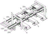
The invention discloses an automatic disassembly and assembly line for a hydraulic support, which comprises an annular ground track, wherein a small track trolley is arranged in the ground track in a matching manner, a top fixing frame is fixedly arranged above the ground track, a top track is horizontally and fixedly arranged in the top fixing frame, the length direction of the top track is vertical to the ground track, a disassembly and assembly mechanism is slidably arranged in the top track and comprises a lifting frame capable of moving up and down, two groups of telescopic clamping heads are symmetrically arranged in the lifting frame and can coaxially rotate, a transmission mechanism is arranged at the position, corresponding to the top track, of the side edge of the ground track, a production line production mode is adopted, the disassembly and assembly of specific parts is carried out at a specific point, the production efficiency is improved, the automatic turnover of a workpiece is realized, and potential safety hazards are eliminated, is favorable for safe production.
Description
Technical Field
The invention relates to the technical field of hydraulic support assembling and disassembling lines, in particular to an automatic assembling and disassembling line for a hydraulic support.
Background
The hydraulic support is a mechanical component changed for preventing and controlling the mine pressure of the coal face. Mining face mine pressure acts on a hydraulic support in an external load mode, the hydraulic support plays a great role in changing the stability of a fully mechanized mining face into a fully mechanized mining face, but after long-time use, the hydraulic support needs to be overhauled or disassembled, but the hydraulic support is complex in internal structure, and has a mechanical structure and a hydraulic cylinder with angles, wherein part of the structure is designed to meet the pressure bearing requirement, the self quality of the hydraulic support is larger, lifting equipment is needed to lift in the disassembling and assembling process, in the prior art, most of the parts after disassembling and assembling are lifted and placed by a crane matched with a crane, but in the operation, the internal space of a workshop is limited, the number of travelling cranes is limited, the disassembling and assembling efficiency of the hydraulic support is low, in the assembling and disassembling process of the parts, because the mounting surface of a workpiece is inconsistent with the placing bearing surface, the workpiece needs to be manually turned over, because the work piece quality is great, artifical when the upset, there is great potential safety hazard, is unfavorable for the safety in production.
Disclosure of Invention
The technical problem to be solved by the invention is to overcome the existing defects and provide an automatic hydraulic support assembling and disassembling line, which adopts a flow line production mode to assemble and disassemble specific parts at specific points, improves the production efficiency, realizes automatic turnover of workpieces, eliminates potential safety hazards, is beneficial to safe production and can effectively solve the problems in the background technology.
In order to achieve the purpose, the invention provides the following technical scheme: the utility model provides an automatic assembly and disassembly line of hydraulic support, includes annular ground track, the inside cooperation installation small rail car of ground track, the fixed top mount that sets up in orbital top of ground, the inside horizontal fixed top track of arranging of top mount, the orbital length direction perpendicular to in top the ground track, the inside slidable mounting dismouting mechanism of top track, dismouting mechanism is including the hoisting frame that can the up-and-down motion, the inside symmetry of hoisting frame sets up two sets of can the concertina dress dops, and two sets of dress dops can coaxial rotation, the orbital side of ground corresponds the position with the top track and sets up transmission device, transmission device's length direction is unanimous with the top track, transmission device's operating height is adjustable.
As a preferred technical scheme of the present invention, the ground rail includes two groups of working rails arranged in a straight and parallel manner, two ends of the working rails are respectively provided with a rail replacing mechanism, the rail replacing mechanism includes a movable rail capable of sliding between the two groups of working rails, the length direction of the movable rail is the same as that of the working rails, when the rail trolley moves to the position of the movable rail, the movable rail moves from the working rail on one side to the working rail on the other side, and is parallel to the working rail on the side, thereby completing rail switching of the rail trolley, realizing circular rotation of the rail trolley in the ground rail, avoiding movement modes such as turning and turning around of the rail trolley, and the like, and being beneficial to ensuring stability of a hydraulic support carried on the rail trolley, avoiding toppling of the hydraulic support, and ensuring production safety.
As a preferred technical scheme of the invention, the rail replacing mechanism further comprises a transverse rail perpendicular to the working rail, the movable rail and the transverse rail are installed in a sliding mode, a lead screw is arranged in the transverse rail in parallel, a first motor is arranged at the end of the lead screw, threads meshed with the lead screw are arranged in the movable rail, the lead screw is driven to rotate through the first motor, the lead screw is meshed with the threads in the movable rail and interacts with the threads, the movable rail is driven to slide axially along the lead screw, and rail switching of the rail trolley is realized.
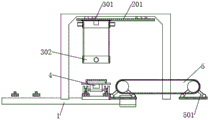
As a preferred technical scheme of the invention, the dismounting mechanism further comprises a sliding frame, the sliding frame is slidably mounted with the top track, a rack is arranged inside the top track along the length direction, a third motor is arranged inside the sliding frame, a gear meshed with the rack is arranged at the end part of an output shaft of the third motor, a pulley block mechanism is arranged between the lifting frame and the sliding frame, the gear is driven to rotate by the third motor and is meshed with the rack, the sliding frame and the lifting frame are driven to horizontally move along the direction vertical to the working track, and therefore the transmission of the workpiece between the rail trolley and the transmission mechanism is realized.
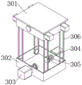
As a preferred technical scheme of the invention, at least two groups of first telescopic parts are horizontally arranged in the lifting frame, the telescopic direction of the first telescopic parts is consistent with that of the clamping heads, a vertical circular ring is fixedly arranged at the free end of the first telescopic parts, the clamping heads and the circular ring are rotatably arranged, and the two groups of clamping heads are pushed by the first telescopic parts to move relatively to clamp a workpiece to be disassembled and assembled.
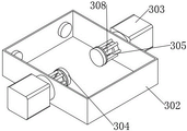
As a preferred technical scheme of the present invention, a spline shaft is disposed at the back of the chuck, a spline sleeve is sleeved outside the spline shaft, a second motor is disposed at an end of the spline sleeve, the second motor is fixedly mounted on the lifting frame, axes of the spline shaft and the spline sleeve are parallel to a telescopic direction of the chuck, and rotation power transmission between the second motor and the chuck is completed through a synergistic effect of the spline shaft and the spline sleeve, and the chuck can be made to be telescopic along a rotation axis.
As a preferred technical scheme of the invention, two ends of a rack of the transmission mechanism are respectively provided with a second telescopic part for driving the transmission mechanism to move up and down, and the transmission mechanism is driven to move up or down integrally through the telescopic action of the second telescopic parts, so that the working height of the transmission mechanism is close to the mounting height of a workpiece to be dismounted, the vertical displacement of the workpiece in the dismounting process is reduced, the time for dismounting the workpiece in the process is reduced, and the dismounting efficiency is improved.
According to a preferable technical scheme of the invention, the upper surface of the small rail car is provided with a rotary disc capable of horizontally rotating, the small rail car is internally provided with a fourth motor, an output shaft of the fourth motor is connected with the central position of the rotary disc, the rotary disc is driven to rotate by the fourth motor, so that the hydraulic support which is loaded on the rotary disc is driven to rotate, the workpiece to be disassembled is matched with the disassembling and assembling mechanism in angle, and the assembling and disassembling head is convenient to assemble and clamp the workpiece to be disassembled and assembled.
According to the preferred technical scheme, the electromagnet is arranged in the working face of the clamping head, the electromagnet is electrified to adsorb the workpiece, and the clamping stability between the clamping head and the workpiece is ensured.
Compared with the prior art, the invention has the beneficial effects that: this automatic dismouting line of hydraulic support adopts pipelined mode of operation, through set up multiunit dismouting equipment in the assembly line, and the inside dedicated equipment that lifts by crane that sets up of every group dismouting equipment, the hoisting frame in the dismouting mechanism promptly, work can not interfere each other, and the dismouting back, the work piece can in time be transported, avoid piling up near the workstation, and, the dress chuck can rotate automatically, it overturns to drive the work piece, make the bearing surface and the ground contact of work piece, avoid non-bearing surface extrusion deformation, guarantee the assembly precision, and the small rail car drives the hydraulic support motion, carry out the operation in step at a plurality of stations, can realize multiunit hydraulic support production online simultaneously, promote production efficiency.
Drawings
FIG. 1 is a schematic structural view of the present invention;
FIG. 2 is a transverse cross-sectional view of the present invention;
FIG. 3 is a longitudinal cross-sectional view of the present invention;
FIG. 4 is a schematic view of the disassembly and assembly mechanism of the present invention;
FIG. 5 is a schematic view of the internal assembly of the lift frame of the present invention;
FIG. 6 is an enlarged view of the invention at A.
In the figure: the device comprises a ground track 1, a working track 101, a movable track 102, a first lead screw 103, a first motor 104, a top fixing frame 2, a top track 201, a disassembly and assembly mechanism 3, a sliding frame 301, a lifting frame 302, a second motor 303, a disassembly and assembly head 304, a first telescopic part 305, a pulley block mechanism 306, a third motor 307, a spline shaft 308, a spline sleeve 309, an electromagnet 310, a 4-rail trolley, a rotary disc 401, a fourth motor 402, a transmission mechanism 5 and a second telescopic part 501.
Detailed Description
The technical solutions in the embodiments of the present invention will be clearly and completely described below with reference to the drawings in the embodiments of the present invention, and it is obvious that the described embodiments are only a part of the embodiments of the present invention, and not all of the embodiments. All other embodiments, which can be derived by a person skilled in the art from the embodiments given herein without making any creative effort, shall fall within the protection scope of the present invention.
Referring to fig. 1-6, the present invention provides a technical solution: the utility model provides an automatic assembly and disassembly line of hydraulic support, including annular ground track 1, 1 inside cooperation installation small rail car 4 of ground track, the fixed top mount 2 that sets up in top track 1's top, 2 inside horizontal fixed top tracks 201 of arranging of top mount, the length direction perpendicular to ground track 1 of top track 201, the inside slidable mounting dismouting mechanism 3 of top track 201, dismouting mechanism 3 is including the hoisting frame 302 that can the up-and-down motion, the inside symmetry of hoisting frame 302 sets up two sets of flexible clamping head 304, two sets of clamping head 304 can coaxial rotation, the side of ground track 1 corresponds the position with top track 201 and sets up transmission mechanism 5, transmission mechanism 5's length direction is unanimous with top track 201, transmission mechanism 5's working height is adjustable.
The rail trolley 4 is a rail trolley with power, and the transmission mechanism 5 is a common transmission belt structure.
The ground track 1 comprises two groups of straight and parallel working tracks 101, two ends of each working track 101 are respectively provided with a track changing mechanism, each track changing mechanism comprises a movable track 102 capable of sliding between the two groups of working tracks 101, the length direction of each movable track 102 is consistent with that of each working track 101, when the rail trolley 4 moves to the position of each movable track 102, each movable track 102 moves from the working track 101 on one side to the working track 101 on the other side and is parallel to the working track 101 on the side, the track switching of the rail trolley 4 is completed at the moment, the circular rotation of the rail trolley 4 in the ground track 1 is realized, the rail trolley is prevented from turning, turning around and other movement modes, the stability of a hydraulic support carried on the rail trolley is guaranteed, the hydraulic support is prevented from toppling over, and the production safety is guaranteed.
The rail changing mechanism further comprises a transverse rail perpendicular to the working rail 101, the movable rail 102 is installed with the transverse rail in a sliding mode, a lead screw 103 is arranged in the transverse rail in parallel, a first motor 104 is arranged at the end portion of the lead screw 103, threads meshed with the lead screw 103 are arranged inside the movable rail 102, the lead screw 103 is driven to rotate through the first motor 104, the lead screw 103 is meshed with the threads in the movable rail 102, interaction is achieved, the movable rail 102 is driven to slide axially along the lead screw 103, and rail switching of the rail trolley 4 is achieved.
The dismounting mechanism 3 further comprises a sliding frame 301, the sliding frame 301 and the top track 201 are installed in a sliding mode, a rack is arranged inside the top track 201 along the length direction, a third motor 307 is arranged inside the sliding frame 301, a gear meshed with the rack is arranged at the end portion of an output shaft of the third motor 307, a pulley block mechanism 306 is arranged between the lifting frame 302 and the sliding frame 301, the third motor 307 drives the gear to rotate, the gear and the rack are meshed, the sliding frame 301 and the lifting frame 302 are driven to horizontally move along the direction perpendicular to the working track 101, and therefore transmission of workpieces between the rail trolley 4 and the transmission mechanism 5 is achieved.
The pulley block mechanism is a simple machine formed by assembling a plurality of movable pulleys and fixed pulleys, the traction rope wound in the pulley block mechanism is used for traction to drive the movable pulleys to move in the vertical direction, the structure is simple, the use is wide, and the repeated description is omitted.
Two sets of first pars contractilis 305 are no less than to the inside horizontal arrangement of hoisting frame 302, and the flexible direction of first pars contractilis 305 is unanimous with the flexible direction of dress chuck 304, and the free end of first pars contractilis 305 is fixed to be arranged vertical ring, and dress chuck 304 rotates the installation with the ring, promotes two equipment dop 304 relative motion through first pars contractilis 305, treats the work piece dress card of dismouting.
The back of the clamping head 304 is provided with a spline shaft 308, the outside of the spline shaft 308 is sleeved with a spline sleeve 309, the end part of the spline sleeve 309 is provided with a second motor 303, the second motor 303 is fixedly installed on the lifting frame 302, the axes of the spline shaft 308 and the spline sleeve 309 are parallel to the telescopic direction of the clamping head 304, the transmission of the rotating power between the second motor 303 and the clamping head 304 is completed through the cooperation of the spline shaft 308 and the spline sleeve 309, and the clamping head 304 can be stretched along the rotating axial direction.
The frame both ends of transmission mechanism 5 set up the second pars contractilis 501 that drives transmission mechanism 5 translation from top to bottom respectively, through the concertina work of second pars contractilis 501, drive transmission mechanism 5's whole shift up or descend to make transmission mechanism 5's working height be close the mounting height of treating the dismouting work piece, thereby reduce the vertical displacement of dismouting in-process work piece, reduce in this process, dismouting work piece required time promotes dismouting efficiency.
When arranging the second expansion parts 501, two sets of second expansion parts 501 are arranged at a single stress point of the transmission mechanism 5, an isosceles triangle is formed between the two sets of expansion parts 501 and the ground, and the stress point is driven to ascend or descend by synchronously extending or shortening the two sets of second expansion parts 501.
The upper surface of small rail car 4 sets up can horizontal pivoted gyration dish 401, and small rail car 4 is inside to set up fourth motor 402, and the output shaft of fourth motor 402 is put with the central point of gyration dish 401 and is connected, drives gyration dish 401 through fourth motor 402 and rotates to drive its hydraulic support rotation of carrying on the back, make and treat to tear open the work piece and dismantle 3 angle matchs of mechanism, the dismouting work piece dress card is treated to the dop 304 of being convenient for.
An electromagnet 310 is arranged in the working face of the clamping head 304, and the electromagnet 310 is electrified to adsorb the workpiece, so that the clamping stability between the clamping head 304 and the workpiece is ensured.
The motors are preferably stepping motors or servo motors, the telescopic parts are preferably cylinders or hydraulic cylinders, the electromagnets 310 are preferably common in the market, the electromagnets 301 are connected with an external power supply through conductive slip rings, and the wiring and control modes of the above elements are common in the prior art.
Before use: the working height of the transmission mechanism 5 should be adjusted to the same position as the mounting height of the workpiece to be mounted at that position according to the mounting and dismounting process.
When in use: if the dismounting process is executed, the hydraulic support is placed on the surface of the rotary disc 401 and moves along with the trolley 4, when the hydraulic support moves to a corresponding station, namely when the hydraulic support moves to a position corresponding to the dismounting mechanism 3, the sliding frame 301 slides to the position above the hydraulic support, the pulley block mechanism 306 drives the lifting frame 302 to move downwards, after the workpiece is dismounted, the workpiece is clamped by the clamping head 304, then the lifting frame 302 moves upwards, the sliding frame 301 slides to the position above the transmission mechanism 5, in the moving process, the second motor 303 drives the clamping head 304 and the workpiece to synchronously rotate, so that the bearing surface of the workpiece faces downwards, then the workpiece is placed on the surface of the transmission mechanism 5, and the workpiece is transferred by the transmission mechanism 5;
if the installation process is executed, the part to be installed is placed on the surface of the transmission mechanism 5, is conveyed to the installation station, moves to the installation position along with the sliding frame 301 and the lifting frame 302 after the clamping head 304 clamps the workpiece, and changes the angle of the part in the moving process, so that the part is suitable for installation.
During the process of disassembly or assembly, the fourth motor 402 can drive the rotary disc 401 and the hydraulic support to rotate, so that the workpiece and the hydraulic support are at the correct installation angle.
When the disassembly or assembly is completed, the rail trolley 4 continues to move to the next station, the next workpiece is disassembled or assembled, and the two stations cannot interfere with each other.
The invention adopts a production line type operation mode, a plurality of groups of dismounting devices are arranged in the production line, and a special hoisting device is arranged in each group of dismounting devices, namely the lifting frames 302 in the dismounting mechanism 3, the mutual work can not interfere with each other, and after dismounting, the workpieces can be timely transported to avoid accumulation near a workbench, moreover, the mounting chuck 304 can automatically rotate to drive the workpieces to overturn, so that the bearing surfaces of the workpieces are contacted with the ground, the non-bearing surfaces are prevented from being squeezed and deformed, the assembly precision is ensured, the rail trolley 4 drives the hydraulic supports to move, the operation is synchronously carried out at a plurality of stations, the simultaneous online production of a plurality of groups of hydraulic supports can be realized, and the production efficiency is improved.
Although embodiments of the present invention have been shown and described, it will be appreciated by those skilled in the art that changes, modifications, substitutions and alterations can be made in these embodiments without departing from the principles and spirit of the invention, the scope of which is defined in the appended claims and their equivalents.
Claims (9)
1. The utility model provides an automatic assembly and disassembly line of hydraulic support, includes annular ground track (1), its characterized in that: a small rail car (4) is arranged inside the ground track (1) in a matching way, a top fixing frame (2) is fixedly arranged above the ground track (1), a top track (201) is horizontally and fixedly arranged in the top fixing frame (2), the length direction of the top track (201) is vertical to the ground track (1), the inside of the top track (201) is provided with a dismounting mechanism (3) in a sliding way, the dismounting mechanism (3) comprises a lifting frame (302) capable of moving up and down, two groups of telescopic clamping heads (304) are symmetrically arranged in the lifting frame (302), the two groups of clamping heads (304) can coaxially rotate, a transmission mechanism (5) is arranged at the position of the side edge of the ground track (1) corresponding to the top track (201), the length direction of the transmission mechanism (5) is consistent with that of the top track (201), and the working height of the transmission mechanism (5) is adjustable.
2. The automated hydraulic support disassembly and assembly line of claim 1, wherein: the ground track (1) comprises two groups of working tracks (101) which are arranged in a straight and parallel mode, rail changing mechanisms are arranged at two ends of each working track (101) respectively, each rail changing mechanism comprises a movable track (102) which can slide between the two groups of working tracks (101), and the length direction of each movable track (102) is consistent with the corresponding working track (101).
3. The automated hydraulic support disassembly and assembly line of claim 2, wherein: the rail replacing mechanism further comprises a transverse rail perpendicular to the working rail (101), the movable rail (102) and the transverse rail are installed in a sliding mode, a lead screw (103) is arranged in the transverse rail in parallel, a first motor (104) is arranged at the end portion of the lead screw (103), and threads meshed with the lead screw (103) are arranged inside the movable rail (102).
4. The automated hydraulic support disassembly and assembly line of claim 1, wherein: dismouting mechanism (3) still include carriage (301), carriage (301) and top track (201) slidable mounting, the rack is arranged along length direction inside top track (201), inside third motor (307) of arranging of carriage (301), the gear with rack toothing is arranged to the output shaft tip of third motor (307), set up assembly pulley mechanism (306) between hoisting frame (302) and carriage (301).
5. The automated hydraulic support disassembly and assembly line of claim 1, wherein: two sets of first pars contractilis (305) are no less than to the inside horizontal arrangement of hoisting frame (302), the flexible direction of first pars contractilis (305) is unanimous with the flexible direction of dress dop (304), the free end of first pars contractilis (305) is fixed and is arranged vertical ring, dress dop (304) with the ring rotates the installation.
6. The automated hydraulic support disassembly and assembly line of claim 1, wherein: the back of dress dop (304) sets up integral key shaft (308), integral key shaft (308) outside suit spline sleeve (309), second motor (303) are arranged to the tip of spline sleeve (309), second motor (303) and hoisting frame (302) fixed mounting, the axis of integral key shaft (308) and spline sleeve (309) is parallel with the flexible direction of dress dop (304).
7. The automated hydraulic support disassembly and assembly line of claim 1, wherein: and two ends of the rack of the transmission mechanism (5) are respectively provided with a second telescopic part (501) for driving the transmission mechanism (5) to move up and down.
8. The automated hydraulic support disassembly and assembly line of claim 1, wherein: the upper surface of the small rail car (4) is provided with a rotary disc (401) capable of horizontally rotating, a fourth motor (402) is arranged inside the small rail car (4), and an output shaft of the fourth motor (402) is connected with the center of the rotary disc (401).
9. The automated hydraulic mount disassembly and assembly line of any of claims 1-8, wherein: an electromagnet (310) is arranged in the working face of the clamping head (304).
Priority Applications (1)
| Application Number | Priority Date | Filing Date | Title |
|---|---|---|---|
| CN201911232899.9A CN110900141B (en) | 2019-12-05 | 2019-12-05 | Automatic assembly and disassembly line for hydraulic supports |
Applications Claiming Priority (1)
| Application Number | Priority Date | Filing Date | Title |
|---|---|---|---|
| CN201911232899.9A CN110900141B (en) | 2019-12-05 | 2019-12-05 | Automatic assembly and disassembly line for hydraulic supports |
Publications (2)
| Publication Number | Publication Date |
|---|---|
| CN110900141A true CN110900141A (en) | 2020-03-24 |
| CN110900141B CN110900141B (en) | 2020-11-17 |
Family
ID=69822534
Family Applications (1)
| Application Number | Title | Priority Date | Filing Date |
|---|---|---|---|
| CN201911232899.9A Active CN110900141B (en) | 2019-12-05 | 2019-12-05 | Automatic assembly and disassembly line for hydraulic supports |
Country Status (1)
| Country | Link |
|---|---|
| CN (1) | CN110900141B (en) |
Cited By (1)
| Publication number | Priority date | Publication date | Assignee | Title |
|---|---|---|---|---|
| CN113738411A (en) * | 2021-06-16 | 2021-12-03 | 南京业恒达智能系统股份有限公司 | Hydraulic support assembly line and assembly method |
Citations (6)
| Publication number | Priority date | Publication date | Assignee | Title |
|---|---|---|---|---|
| JP2005186174A (en) * | 2003-12-24 | 2005-07-14 | Shinmei Ind Co Ltd | Conveyer apparatus |
| CN101456128A (en) * | 2007-12-12 | 2009-06-17 | 柯马公司 | Method and apparatus forassembling a complex product ina parrallel process system |
| CN204421638U (en) * | 2014-12-12 | 2015-06-24 | 铜陵有色股份铜冠电工有限公司 | A kind of automatic charging equipment for connected furnace |
| CN205237476U (en) * | 2015-12-29 | 2016-05-18 | 中信戴卡股份有限公司 | Online compressed steel of modified wheel cover device |
| CN205633965U (en) * | 2016-05-10 | 2016-10-12 | 北京瑞华康源科技有限公司 | Rail replacer |
| CN206142431U (en) * | 2016-10-10 | 2017-05-03 | 杨萌茜 | A conveyer for gearbox assembly |
-
2019
- 2019-12-05 CN CN201911232899.9A patent/CN110900141B/en active Active
Patent Citations (6)
| Publication number | Priority date | Publication date | Assignee | Title |
|---|---|---|---|---|
| JP2005186174A (en) * | 2003-12-24 | 2005-07-14 | Shinmei Ind Co Ltd | Conveyer apparatus |
| CN101456128A (en) * | 2007-12-12 | 2009-06-17 | 柯马公司 | Method and apparatus forassembling a complex product ina parrallel process system |
| CN204421638U (en) * | 2014-12-12 | 2015-06-24 | 铜陵有色股份铜冠电工有限公司 | A kind of automatic charging equipment for connected furnace |
| CN205237476U (en) * | 2015-12-29 | 2016-05-18 | 中信戴卡股份有限公司 | Online compressed steel of modified wheel cover device |
| CN205633965U (en) * | 2016-05-10 | 2016-10-12 | 北京瑞华康源科技有限公司 | Rail replacer |
| CN206142431U (en) * | 2016-10-10 | 2017-05-03 | 杨萌茜 | A conveyer for gearbox assembly |
Cited By (1)
| Publication number | Priority date | Publication date | Assignee | Title |
|---|---|---|---|---|
| CN113738411A (en) * | 2021-06-16 | 2021-12-03 | 南京业恒达智能系统股份有限公司 | Hydraulic support assembly line and assembly method |
Also Published As
| Publication number | Publication date |
|---|---|
| CN110900141B (en) | 2020-11-17 |
Similar Documents
| Publication | Publication Date | Title |
|---|---|---|
| CN204913913U (en) | Four -axis stirring machinery hand | |
| CN105947613A (en) | Automatic turnover machine | |
| CN106241328B (en) | Lifting translating device on transmission line body | |
| CN112340266A (en) | Assembling device and assembling method for tank body swash plate | |
| CN110900141B (en) | Automatic assembly and disassembly line for hydraulic supports | |
| CN102363255B (en) | Welding tilter | |
| CN112059454B (en) | H-shaped steel assembling mechanism | |
| CN109761059B (en) | Green brick stacking robot | |
| CN112238336A (en) | Double-station differential bearing press-fitting and bolt tightening device | |
| CN112029976A (en) | Double-station rotating material table | |
| CN108996132B (en) | TLED fluorescent tube automatic turning device for conveyor | |
| CN107598523B (en) | Brake disc preassembling device and method | |
| CN113526092B (en) | Rotary double-layer rolling machine | |
| CN214721902U (en) | Gantry type positioner | |
| CN201580805U (en) | Blank chain-type conveying device | |
| CN104029183A (en) | Four-station parallel rotating table | |
| CN114643526A (en) | Rectangular metal shell polishing device and polishing method thereof | |
| CN210703417U (en) | Camshaft static pressure combined system | |
| CN209922178U (en) | Tire lane dividing equipment | |
| CN207375217U (en) | A kind of conveying mechanism | |
| CN202238943U (en) | Fully-hydraulic-driven steel turning device for use before blooming mill | |
| CN217096813U (en) | Automatic control technology-based material processing tool rack | |
| CN220392367U (en) | Relay conveying device | |
| CN220951016U (en) | Lifting transmission platform for mechanical control process curve | |
| CN215700093U (en) | Special container turnover mechanism |
Legal Events
| Date | Code | Title | Description |
|---|---|---|---|
| PB01 | Publication | ||
| PB01 | Publication | ||
| SE01 | Entry into force of request for substantive examination | ||
| SE01 | Entry into force of request for substantive examination | ||
| GR01 | Patent grant | ||
| GR01 | Patent grant |