CN110897226A - Electric component wearing unit for air-conditioning clothes and air-conditioning clothes - Google Patents
Electric component wearing unit for air-conditioning clothes and air-conditioning clothes Download PDFInfo
- Publication number
- CN110897226A CN110897226A CN201911127239.4A CN201911127239A CN110897226A CN 110897226 A CN110897226 A CN 110897226A CN 201911127239 A CN201911127239 A CN 201911127239A CN 110897226 A CN110897226 A CN 110897226A
- Authority
- CN
- China
- Prior art keywords
- fan
- air
- conditioning
- unit
- electrical component
- Prior art date
- Legal status (The legal status is an assumption and is not a legal conclusion. Google has not performed a legal analysis and makes no representation as to the accuracy of the status listed.)
- Pending
Links
Images


Classifications
-
- A—HUMAN NECESSITIES
- A41—WEARING APPAREL
- A41D—OUTERWEAR; PROTECTIVE GARMENTS; ACCESSORIES
- A41D13/00—Professional, industrial or sporting protective garments, e.g. surgeons' gowns or garments protecting against blows or punches
- A41D13/002—Professional, industrial or sporting protective garments, e.g. surgeons' gowns or garments protecting against blows or punches with controlled internal environment
- A41D13/005—Professional, industrial or sporting protective garments, e.g. surgeons' gowns or garments protecting against blows or punches with controlled internal environment with controlled temperature
-
- A—HUMAN NECESSITIES
- A41—WEARING APPAREL
- A41D—OUTERWEAR; PROTECTIVE GARMENTS; ACCESSORIES
- A41D13/00—Professional, industrial or sporting protective garments, e.g. surgeons' gowns or garments protecting against blows or punches
- A41D13/002—Professional, industrial or sporting protective garments, e.g. surgeons' gowns or garments protecting against blows or punches with controlled internal environment
- A41D13/0025—Professional, industrial or sporting protective garments, e.g. surgeons' gowns or garments protecting against blows or punches with controlled internal environment by means of forced air circulation
-
- F—MECHANICAL ENGINEERING; LIGHTING; HEATING; WEAPONS; BLASTING
- F04—POSITIVE - DISPLACEMENT MACHINES FOR LIQUIDS; PUMPS FOR LIQUIDS OR ELASTIC FLUIDS
- F04D—NON-POSITIVE-DISPLACEMENT PUMPS
- F04D25/00—Pumping installations or systems
- F04D25/02—Units comprising pumps and their driving means
- F04D25/06—Units comprising pumps and their driving means the pump being electrically driven
- F04D25/0673—Battery powered
-
- F—MECHANICAL ENGINEERING; LIGHTING; HEATING; WEAPONS; BLASTING
- F04—POSITIVE - DISPLACEMENT MACHINES FOR LIQUIDS; PUMPS FOR LIQUIDS OR ELASTIC FLUIDS
- F04D—NON-POSITIVE-DISPLACEMENT PUMPS
- F04D25/00—Pumping installations or systems
- F04D25/02—Units comprising pumps and their driving means
- F04D25/08—Units comprising pumps and their driving means the working fluid being air, e.g. for ventilation
- F04D25/084—Units comprising pumps and their driving means the working fluid being air, e.g. for ventilation hand fans
-
- F—MECHANICAL ENGINEERING; LIGHTING; HEATING; WEAPONS; BLASTING
- F04—POSITIVE - DISPLACEMENT MACHINES FOR LIQUIDS; PUMPS FOR LIQUIDS OR ELASTIC FLUIDS
- F04D—NON-POSITIVE-DISPLACEMENT PUMPS
- F04D25/00—Pumping installations or systems
- F04D25/02—Units comprising pumps and their driving means
- F04D25/08—Units comprising pumps and their driving means the working fluid being air, e.g. for ventilation
- F04D25/12—Units comprising pumps and their driving means the working fluid being air, e.g. for ventilation the unit being adapted for mounting in apertures
-
- F—MECHANICAL ENGINEERING; LIGHTING; HEATING; WEAPONS; BLASTING
- F24—HEATING; RANGES; VENTILATING
- F24F—AIR-CONDITIONING; AIR-HUMIDIFICATION; VENTILATION; USE OF AIR CURRENTS FOR SCREENING
- F24F1/00—Room units for air-conditioning, e.g. separate or self-contained units or units receiving primary air from a central station
- F24F1/02—Self-contained room units for air-conditioning, i.e. with all apparatus for treatment installed in a common casing
- F24F1/04—Arrangements for portability
-
- F—MECHANICAL ENGINEERING; LIGHTING; HEATING; WEAPONS; BLASTING
- F24—HEATING; RANGES; VENTILATING
- F24F—AIR-CONDITIONING; AIR-HUMIDIFICATION; VENTILATION; USE OF AIR CURRENTS FOR SCREENING
- F24F2221/00—Details or features not otherwise provided for
- F24F2221/12—Details or features not otherwise provided for transportable
-
- F—MECHANICAL ENGINEERING; LIGHTING; HEATING; WEAPONS; BLASTING
- F25—REFRIGERATION OR COOLING; COMBINED HEATING AND REFRIGERATION SYSTEMS; HEAT PUMP SYSTEMS; MANUFACTURE OR STORAGE OF ICE; LIQUEFACTION SOLIDIFICATION OF GASES
- F25D—REFRIGERATORS; COLD ROOMS; ICE-BOXES; COOLING OR FREEZING APPARATUS NOT OTHERWISE PROVIDED FOR
- F25D2400/00—General features of, or devices for refrigerators, cold rooms, ice-boxes, or for cooling or freezing apparatus not covered by any other subclass
- F25D2400/26—Refrigerating devices for cooling wearing apparel, e.g. garments, hats, shoes or gloves
Abstract
An air-conditioning clothing electrical component wearing unit (100) that is used in combination with a clothing main body having an opening hole (53) for a fan and is worn on the body, the air-conditioning clothing electrical component wearing unit comprising: a fan (1) for introducing air from the outside into the garment body; a wearing mechanism (belt body (21)) for wearing the fan (1) on the body; and a fan mounting mechanism (15) for mounting the fan (1) to the attachment mechanism, wherein a fan-side coupling portion (16) for coupling to the fan opening hole (53) is formed in the fan (1).
Description
The present application is a divisional application of patent applications with application number 201780015113.0, entitled electrical component wearing unit for air-conditioning clothes and air-conditioning clothes, filed on 03/08/2017 by the applicant.
Technical Field
The present invention relates to an air-conditioning garment electrical component attachment unit for an air-conditioning garment for cooling a body, and an air-conditioning garment.
Background
In recent years, air-conditioning clothes for cooling the body have been put into practical use and are rapidly spreading. As shown in fig. 35A and 35B, the conventional air-conditioning garment 101 includes: a garment main body 110 sewn from a raw material having low air permeability; two fans 140, 140 installed below the rear side of the garment body 110; a power supply device (not shown) for supplying electric power to the two fans 140, 140; and a power cable (not shown) for electrically connecting the power supply device to the two fans 140, 140.
When the fan 140 is operated, a large amount of air is introduced from the fan 140 into the garment body 110. An air flow passage is automatically formed between the garment body 110 and the body or underwear by the pressure of the introduced air, and the introduced air flows upward along the surface of the body or underwear in the formed air flow passage, and is discharged to the outside from the periphery of the collar portion or the cuff portion, for example. Here, the surrounding of the collar and the cuff function as the air outlet 130.
While the air is flowing through the air flow path between the garment body 110 and the body or underwear, the air evaporates sweat flowing out of the body, and cools the body by the heat of vaporization at the time of evaporation (see, for example, patent document 1).
Various measures are implemented for such conventional air-conditioning clothes 101 so that the weight of the fan 140 can be borne and the fan 140 does not fall off from the clothes main body 110 even if pressure is applied to the fan 140 from various directions.
For example, in the case of the normal air-conditioning garment 101, the material of the garment main body 110 used is cloth. Since such cloth is stretchable, the fan 140 is easily detached by a small force, and thus, by performing special processing on the mounting hole of the fan 140, for example, processing on a reinforcing plate of a sewn plastic plate, the cloth is not damaged by the weight of the fan 140, and the fan 140 can be reliably fixed.
Patent document 1: international publication No. 2005/063065
However, the conventional air-conditioning garment 101 has the following problems: a special mounting hole for mounting the fan 140 must be formed in the garment body 110 of the air-conditioning garment, resulting in a trouble in manufacturing. Further, since the fan 140 and the power supply device are attached to clothes, there is a problem that the electrical components cannot be completely prevented from falling.
Further, by attaching the fan 140 to the garment body 110, there may be problems as follows: the air-conditioning clothes 101 becomes heavy as a whole, or the vicinity of the mounting hole of the fan 140 is greatly expanded by the positive pressure generated by the introduction of the outside air, which hinders the work.
Further, since the fan 140 is attached to the garment body 110, that is, the fan 140 is suspended from the garment body 110, there are various problems as described below.
1 when the body is rotated, the fan 140 is further moved away from the body by centrifugal force, increasing the probability of collision to the surroundings.
For example, when the fan 140 receives an external force from various directions, such as when an object collides with the fan 140 or when a user jumps, an impact is applied to the fan 140 or the inside of the fan 140, and a strong structure capable of withstanding the impact is required. In particular, in order to prevent the screw propeller from falling off due to impact and to increase the fitting force between the screw propeller and the shaft of the motor, the bearing of the motor is deformed when the screw propeller is pressed into the shaft of the motor, which causes noise.
3 when the propeller rotates, vibration is generated due to imbalance of blades of the propeller, etc. Further, although vibration adversely affects the life of the motor and the generation of noise, it is not easy to take measures such as absorbing noise if the motor is in a floating state.
Disclosure of Invention
The invention provides an electric component wearing unit for air-conditioning clothes and the air-conditioning clothes, which can prevent the electric components from falling off and can easily install a fan without forming a special installation hole on the clothes body of the air-conditioning clothes.
In order to achieve the above object, the invention according to claim 1 is an electrical component attachment unit for an air-conditioning garment, which is used in combination with a garment body having an opening hole for a fan and is attached to a body, the electrical component attachment unit comprising:
a fan for introducing air from the outside into the garment body;
a wearing mechanism for wearing the fan on a body; and
a fan mounting mechanism for mounting the fan to the attachment mechanism,
the fan is formed with a fan-side coupling portion for coupling with the fan opening hole.
The invention described in claim 2 is the air-conditioning clothing electrical component wearing unit described in claim 1, wherein,
the fan comprises a fan body and a cover part, wherein the cover part is used for accommodating the fan body,
the fan-side coupling portion is a cylindrical coupling portion formed in the cover portion.
The invention described in claim 3 is the air-conditioning clothing electrical component wearing unit described in claim 2, wherein,
an upper flange is provided on an air intake side of the cylindrical coupling portion, and a lower flange is provided on an air delivery side of the upper flange,
the opening edge of the garment body having the fan opening hole is fitted into a groove formed between the upper flange and the lower flange.
The invention described in claim 4 is the air-conditioning clothing electrical component wearing unit according to any one of claims 1 to 3,
the wearing mechanism is a rope, a belt or a belt-shaped object formed by a combination of the rope and the belt.
The invention described in claim 5 is the air-conditioning clothing electrical component wearing unit described in claim 4, wherein,
some or all of the wearing mechanism has elasticity, or the wearing mechanism has a length adjustment mechanism.
The invention described in claim 6 is the air-conditioning clothing electrical component wearing unit according to claim 4 or 5, wherein,
the clothes main body is a front-opening clothes, and is provided with an opening and closing mechanism for opening and closing the left and right forebodies,
the wearing mechanism has both ends attached to the left and right front bodies, respectively, so that the garment main body forms a part of the wearing mechanism, and the opening and closing mechanism forms a connecting mechanism of the wearing mechanism.
The invention described in claim 7 is the air-conditioning clothing electrical component wearing unit described in any one of claims 4 to 6,
the number of the fans is two, and the two fans are connected through a power cable.
The invention according to claim 8 is the air-conditioning clothing electrical component wearing unit according to any one of claims 4 to 7, wherein,
the fan mounting mechanism is detachably mounted to the attachment mechanism.
The invention according to claim 9 is the air-conditioning clothing electrical component wearing unit according to any one of claims 4 to 8,
the fan mounting device is provided with a movable mechanism which enables the fan to move along the longitudinal direction of the mounting mechanism after the fan is mounted on the mounting mechanism.
The invention described in claim 10 is the air-conditioning clothing electrical component wearing unit described in claim 3, wherein,
a power supply part for supplying power to the fan and a power supply cable,
the fan, the power cable, and the power unit are connected to each other, thereby functioning as a part of the attachment mechanism.
The invention described in claim 11 is an electrical component attachment unit for air-conditioning clothing according to any one of claims 1 to 10, including:
a power supply unit configured to supply power to the fan; and
and a power supply unit attachment mechanism for attaching the power supply unit to the attachment mechanism.
The invention according to claim 12 is the air-conditioning clothing electrical component wearing unit according to any one of claims 1 to 3, wherein,
the fan control device is provided with a unit part which is formed by integrating the fan and a power supply part for supplying power to the fan.
The invention described in claim 13 is the air-conditioning clothing electrical component wearing unit described in claim 12, wherein,
the unit portion seals the motor and the power supply portion in a sealed container.
The invention described in claim 14 is the air-conditioning clothing electrical component wearing unit described in claim 12 or 13, wherein,
the unit section includes:
an electric component wearing plate which is worn on the back or on the chest; and
and a fan attachment mechanism that detachably fixes the fan to the electric component mounting plate.
The invention according to claim 15 is the air-conditioning clothing electrical component wearing unit according to any one of claims 12 to 14,
the fan is provided with an air improving means for removing substances harmful to the body from the air introduced from the outside or the air after the introduction, for containing substances useful to the body in the air, or for cooling the air, in the vicinity of the air introduction port.
The invention described in claim 16 is the air-conditioning clothing electrical component wearing unit described in any one of claims 1 to 15, further including:
a power supply unit configured to supply power to the fan; and
a solar panel,
the power supply unit includes an electric storage mechanism for using or storing electricity generated by the solar panel.
The invention described in claim 17 is the air-conditioning clothing electrical component wearing unit described in any one of claims 1 to 16, further including:
a power supply unit configured to supply power to the fan;
a communication mechanism that communicates with an external device; and
and a control unit that controls the communication unit and controls on/off of the power supply unit and/or a rotation speed of the fan based on an instruction received from the external device.
The invention described in claim 18 is the air-conditioning clothing electrical component wearing unit described in any one of claims 1 to 17, further including:
a power supply unit configured to supply power to the fan;
a measurement unit that measures important information; and
and a control means for controlling on/off of the power supply unit and/or a rotation speed of the fan based on a measurement result of the measurement means.
The invention described in claim 19 is the air-conditioning clothing electrical component attachment unit described in claim 18, wherein,
comprises a communication means for communicating with an external device,
the control means controls the communication means and transmits the measurement result of the measurement means to an external device.
The invention described in claim 20 is an air-conditioning garment, including:
the air-conditioning garment electrical component wearing unit according to any one of claims 1 to 19; and
a garment main body which is formed of a sheet-like material having the opening hole for the fan and covers at least a part of the body,
the cylindrical connection portion of the fan is fitted into the fan opening hole.
The invention according to claim 21 is characterized in that, in addition to the air-conditioning garment according to claim 20,
the periphery of the opening edge portion of the garment body, in which the fan opening hole is formed, is stretchable.
The invention according to claim 22 is the air-conditioning garment according to claim 20 or 21, wherein,
the fan is disposed on the front part of the garment body, and a spacer is disposed between the back part of the garment body and the body.
The invention described in claim 23 is an air-conditioning garment, including:
the air-conditioning garment electrical component wearing unit according to any one of claims 4 to 10; and
a garment main body which is formed of a sheet-like material having the fan opening hole and covers at least a part of a body;
the air-conditioning clothing electrical component wearing unit is worn on the body by attaching both ends of the wearing mechanism constituting the air-conditioning clothing electrical component wearing unit to the vicinity of the opening/closing mechanism of the corresponding clothing main body and switching the opening/closing mechanism from the open state to the closed state.
The invention according to claim 24 is the air-conditioning garment according to any one of claims 20 to 23, characterized in that,
the clothes main body is made of plastic film.
The invention according to claim 25 is the air-conditioning garment according to any one of claims 20 to 24, characterized in that,
the clothes main body is provided with an air discharge part,
the air discharge unit includes a discharge resistance adjustment mechanism for adjusting a discharge resistance of the discharged air.
According to the present invention, there are provided an electric component attachment unit for air-conditioning clothing and air-conditioning clothing capable of preventing an electric component from falling off and easily attaching a fan without forming a special attachment hole in a clothing body of the air-conditioning clothing.
Drawings
Fig. 1 is a schematic side view showing an example of a fan of an electrical component mounting unit for air-conditioning clothing according to a first embodiment.
Fig. 2A is a schematic front view of the electrical component mounting tape.
Fig. 2B is a schematic front view of an electrical component mounting belt (electrical component mounting unit for air-conditioning clothes) on which a fan and a power supply unit are mounted.
Fig. 2C is a schematic side view of an electrical component mounting belt (electrical component mounting unit for air-conditioning clothes) on which a fan and a power supply unit are mounted.
Fig. 3 is a schematic front view showing an example of a garment body using the air-conditioning garment electrical component attachment unit of the first embodiment.
Fig. 4 is a schematic side view showing a state where the fan is attached to the garment body.
Fig. 5 is a schematic front view showing a state in which the garment main body to which the air-conditioning garment electrical component attachment unit of the first embodiment is attached is worn.
Fig. 6 is a schematic side view showing another example of the fan.
Fig. 7 is a schematic side view showing another state of the air-conditioning clothing electrical component mounting unit.
Fig. 8 is a schematic side view showing another state in which the fan is attached to the garment body.
Fig. 9 is a schematic side view of a fan of the second embodiment.
Fig. 10 is a schematic front view of a power supply unit according to the second embodiment.
Fig. 11A is a schematic diagram showing a state before the terminal of the power cable is coupled to the terminal of the power unit.
Fig. 11B is a schematic diagram showing a state in which the terminal of the power cable is coupled to the terminal of the power unit.
Fig. 12 is a front view of the entire air conditioning unit of the second embodiment.
Fig. 13 is a schematic front view of the air conditioning unit when attached to the body.
Fig. 14 is a schematic view showing a fan and a fan connected by an opening hole while wearing clothes.
Fig. 15A is a schematic front view showing an example of a unit section of the third embodiment in which a fan and a power supply section are integrated.
Fig. 15B is a schematic side view showing an example of a unit section of the third embodiment in which a fan and a power supply section are integrated.
Fig. 16 is a schematic rear view showing a state where the unit section is carried on the back.
Fig. 17 is a schematic rear view showing a state where the garment main body having the unit section is worn.
Fig. 18 is a schematic cross-sectional view showing a state where the garment main body having the unit section is worn.
Fig. 19A is a schematic front view of an electric component mounting plate of a mounting portion as a modification.
Fig. 19B is a schematic side view of an electric component mounting plate of a mounting portion as a modification.
Fig. 20 is a schematic front view of the power supply unit.
Fig. 21 is a schematic side view of the fan.
Fig. 22 is a schematic side view of a unit section in which a fan having a power supply unit mounted thereon is mounted on an electrical component mounting plate.
Fig. 23 is a circuit block diagram of a unit section according to a modification of the third embodiment.
Fig. 24A is a schematic front view of a modified air-conditioning garment when worn.
Fig. 24B is a schematic rear view when the air-conditioning garment of the modification is worn.
Fig. 25A is a schematic side view of a unit section of the fourth embodiment to which an optional container for the same purpose as in the case of using a filter or a water-containing sponge is attached.
Fig. 25B is a schematic side view of a unit section to which a rain cover for sucking in outside air from a lower side where rainwater cannot enter is attached.
Fig. 25C is a schematic side view of a unit portion to which a container containing granular dry ice (coolant) or the like is attached.
Fig. 26 is a schematic sectional view of a unit section of the fourth embodiment.
FIG. 27 is a schematic front view of a hydrous sponge.
Fig. 28 is a schematic view of an electrical component mounting belt constituting the electrical component mounting unit for air-conditioning clothing according to the fifth embodiment.
Fig. 29A is a schematic side view of the fan of the fifth embodiment.
Fig. 29B is a schematic rear view of the fan of the fifth embodiment.
Fig. 29C is a schematic rear view of the fan in a state of being attached to the belt body.
Fig. 30 is a schematic front view of the air-conditioning garment in which the electrical component mounting unit for an air-conditioning garment according to the fifth embodiment is attached, showing a state in which the front is open.
Fig. 31A is a diagram showing an air-conditioning garment according to the sixth embodiment, and is a schematic front view of the garment body.
Fig. 31B is a diagram showing an air-conditioning garment according to the sixth embodiment, and is a schematic cross-sectional view of the waist of the garment body to which a fan is attached when the garment body is worn with the fan attached.
Fig. 32 is a schematic side view showing an example of the integrated fan and power cable.
Fig. 33 is an explanatory view showing another example of the electric component mounting tape.
Fig. 34A is an explanatory view showing an example of a case where a half-sleeved garment is used as a garment body of the air-conditioning garment.
Fig. 34B is an explanatory view showing an example of a case where a long-sleeved garment is used as the garment body of the air-conditioning garment.
Fig. 35A is a schematic front view showing an example of a conventional air-conditioning garment.
Fig. 35B is a schematic rear view showing an example of a conventional air-conditioning garment.
Detailed Description
(embodiment mode)
Hereinafter, embodiments for carrying out the invention according to the present application will be described with reference to the drawings. However, the scope of the invention is not limited to the examples of the figures.
(first embodiment)
The case where the air-conditioning clothes using the air-conditioning clothes electric component wearing unit of the present invention is used for a rental purpose in a sporting facility or the like without a cooling device will be described. The present invention is described in detail with reference to the accompanying drawings.
First, the fan will be explained.
Fig. 1 is a schematic side view of a fan 1. Fan 1 includes fan main body FN11, and cover CV11 for housing fan main body FN11 (cover CV11 includes air intake portion 11, cylindrical coupling portion 16 as a cylindrical coupling portion, flange 12 projecting outward from the middle of cylindrical coupling portion 16, air delivery portion 14, and fan attachment mechanism 15). For example, the fan attachment mechanism 15 is a strong clip formed on the bottom surface of the fan, which strongly clips a belt-like object body described later, and can prevent the electrical component from dropping even when a violent operation is performed.
Fan main body FN11 includes, for example, a propeller fan and a motor for rotating the propeller fan, and fan main body FN11 is housed inside cover unit CV 11. Cover CV11 has a cylindrical coupling portion 16 formed between air intake portion 11 and air delivery portion 14 facing each other, and a fan attachment mechanism 15 provided on the side of air delivery portion 14.
The tubular coupling portion 16 is inserted into a fan opening hole 53 formed in a garment body of the air-conditioning garment, and thereby functions as a fan-side coupling portion for coupling the fan 1 to the garment body.
Further, a flange 12 is provided between the cylindrical coupling portion 16 and the air sending portion 14. An annular groove 161 is formed in the outer peripheral surface of the cylindrical coupling portion 16 above the flange.
Next, the electric component mounting belt 2 as a wearing portion will be described.
Fig. 2A is a schematic front view of the electrical component mounting belt 2. The belt body (wearing mechanism) 21 has substantially the same structure as a belt used for pants, and is attached to a portion corresponding to a side surface of a body, and is configured with a mounting adjustment mechanism 23 so that the length thereof can be adjusted. For example, the electrical component mounting belt 2 is a belt having a width of about 6cm, and has a power cable fixing mechanism (not shown) at an appropriate position.
Fig. 2B and 2C are a schematic front view and a schematic side view of the electrical component mounting belt 2 (electrical component attachment unit 100 for air-conditioning clothing) to which the fan 1 and the power supply unit 3 are attached. The power supply unit 3 is attached to the center by a clip as the power supply unit attachment means 31, the fan 1 is connected by the power supply cable 4, and the fan 1 is attached by a clip as the fan attachment means 15. In this way, all the electric components are collectively mounted on the electric component mounting belt 2.
Next, the disposable garment body will be explained.
Here, a case will be described in which the garment main body is made based on an existing 45-liter polyethylene bag (hereinafter referred to as a plastic bag).
For example, a 45L plastic bag is used, which is a transparent plastic bag having a size of 65cm in width, 80cm in length, and 0.02mm in thickness.
Fig. 3 is a schematic front view of the garment body 5 with the seal portion on top, the broken line indicates the 45L plastic bag itself, and the solid line indicates the garment body subjected to the following cutting and opening processing 1 to 3.
1 cutting the cloth 51 and the neck 52 to form a vest shape.
2 the lower side portions of the left and right abdominal portions (at positions 15cm from the center, respectively) are cut into a circular shape with a diameter slightly smaller than the diameter of the cylindrical coupling portion 16 of the fan 1, and the fan opening hole 53 is opened.
3A hem threading mechanism (Japanese bottom section コード pass through し)54 is formed at the hem portion.
Here, differences between the mounting hole of the fan of the conventional air-conditioning garment and the opening hole 53 for the fan of the present embodiment will be described. In a conventional air-conditioning garment, a fan is mounted on a garment body. Therefore, the mounting hole of the fan 1 needs to be sufficiently reinforced as described above.
In contrast, in the present embodiment, the fan 1 is attached to the electrical component attachment belt 2, and no force is applied between the fan 1 and the garment main body 5, so that in the present embodiment, only the holes need to be opened. That is, it is possible to provide the electrical component mounting unit 100 for air-conditioning clothing capable of completely preventing the electrical components from falling off without forming a special mounting hole for mounting the fan 1 to the clothing main body 5.
Next, the preparation for rental will be described.
An electric component mounting belt-like article 2 (electric component mounting unit 100 for air-conditioning clothes) and a clothes main body 5 are rented, wherein the electric component mounting belt-like article 2 (electric component mounting unit 100 for air-conditioning clothes) is provided with two fans 1, a power supply part 3 and a power supply cable 4, and the clothes main body 5 is provided with a wire material (Japanese: コード) at a lower hem part threading mechanism 54.
Next, the procedure used by the user will be described.
First, the electrical component attachment belt 2 (the electrical component attachment unit 100 for air-conditioning clothes) is wound around the trunk, and then the garment body 5 is put on.
Further, the fan opening hole 53 is inserted into the tubular coupling portion 16 from the outside of the fan 1, the edge of the fan opening hole 53 is dropped into the groove 161 formed above the flange 12, and the edge of the fan opening hole 53 is coupled to the tubular coupling portion 16 of the fan so as to be close to the upper surface of the flange 12. The polyethylene film can be easily connected because the material itself has elasticity.
Fig. 4 is an explanatory diagram for explaining a relationship between the fan 1 and the fan opening hole 53.
As shown in fig. 4, after the edge of the fan opening 53 formed in the clothing main body 5 is inserted into the tubular coupling portion 16, it falls into the tubular coupling portion 16, which is a portion of the groove 161 having a smaller diameter than the outer peripheral surface of the tubular coupling portion 16, and in this state, it is stable, and the clothing main body 5 is coupled to the fan 1. In this case, the tubular coupling portion 16 of the fan 1 functions as a fan-side coupling portion.
Finally, the wire passing through the lower swing portion threading mechanism 54 is tightened by a wire stopper (not shown), and then the power supply portion 3 is operated to operate the fan 1.
Fig. 5 is a schematic front view showing a state in which the belt-like article 2 (the air-conditioning clothing electrical component wearing unit 100) and the clothing main body 5 are worn on a T-shirt TS51 having a circular pattern and are used.
When the wire material passed through the hem threading mechanism 54 is tightened (air leakage prevention mechanism), air introduced by the fan 1 is blown into the clothes main body 5 without leaking from the hem, and the space between the clothes main body 5 and the T-shirt TS51 worn on the lower surface is made positive pressure, automatically forms an air flow passage, and is discharged while moving upward toward the neckline and the arms (functioning as air discharge portions). That is, the air in the garment body 5 is ventilated.
The cooling effect by the circulation of air and the evaporation of sweat due to the circulation of air is the same as that of the conventional air-conditioning clothes.
Further, since the garment main body 5 is made of a polyethylene film, air leakage from the garment main body 5 cannot be avoided in the conventional air-conditioning garment. Further, since the garment main body 5 is transparent, only the fan 1, the power supply unit 3, and the power supply cable 4 can be seen, and the T-shirt TS51 having a dot pattern can be seen through the other portions, so that the sense of discomfort in appearance is greatly reduced.
In addition, although the above-described manufacturing method is described based on the conventional 45L plastic bag, it is needless to say that it is reasonable to consider a method of manufacturing the clothes main body 5 for air-conditioning clothes from the beginning.
In the air-conditioning garment of the first embodiment, since the electric component mounting strip 2 is used and the fan 1 is fixed to the electric component mounting strip 2, no load is applied to the garment main body 5, and therefore, not only the above-described "problem" can be solved, but also the following great advantages are present in the garment main body as compared with the conventional air-conditioning garment.
1 since the weight of the fan 1 is not applied to the fan opening 53 of the garment body 5 at all, it is not necessary to reinforce the fan opening 53.
2 since the reinforcement of the fan opening 53 is not required, a plastic film of 0.05mm or less can be used as a material of the garment body 5.
(modification example)
The air-conditioning clothing electrical component attachment unit 100a that can be used in various clothing bodies will be described.
Fig. 6 is a schematic side view of the fan 1a used in the present modification.
In the present modification, as shown in fig. 6, the fan main body (not shown) is housed inside the cover portion in the tubular coupling portion 16. This cover portion has a tubular coupling portion 16 formed between the air intake portion 11 and the air delivery portion 14 facing each other, and a fan attachment mechanism 15 is provided on the side of the air delivery portion 14. An upper flange 121 and a lower flange 122 are formed on the upper and lower sides of the outer peripheral surface of the tubular coupling portion 16, and an annular groove 161 is formed in the gap between the upper flange 121 and the lower flange 122. In the fan 1 shown in fig. 1 used in the first embodiment, a part of the cylindrical connecting portion 16 above the groove 161 can be regarded as the upper flange 121.
The tubular coupling portion 16 is inserted into a fan opening hole 53 formed in the garment body of the air-conditioning garment, and thereby functions as a fan-side coupling portion for coupling the fan 1 to the garment body.
The fan mounting mechanism 15 is, for example, a flat through hole (for example, a flat hole having a width of 26 mm) as a movable mechanism for passing through the belt main body 2 a. In this case, although the fan 1 can move on the belt-like object main body 2a, the fan 1 is not dropped even if the fan moves on the belt-like object main body 2a during use, and therefore the fan 1 can be said to be reliably fixed to the belt-like object main body 2 a.
Fig. 7 is a schematic side view of the assembled electrical component mounting strip 2 a. The electric component mounting strip 2a is substantially the same as the strip used in the first embodiment, but has a width of, for example, 25mm and is thinner than the electric component mounting strip 2.
Next, an assembling method of the electrical component mounting strip 2a will be described.
Fig. 7 is a schematic side view of the assembled electrical component mounting strip 2a (electrical component attachment unit for air-conditioning clothes 100 a).
The flat through hole of the fan 1a as the fan attachment mechanism 15 is passed through the belt from the end of the belt main body 2a on the side where the adjustment mechanism 23 is not attached, and the fan 1a is moved to the left and right of the portion corresponding to the center of the abdomen (for example, to the left and right positions of about 15 cm).
Next, the power supply unit 3 is mounted at the center, and the power supply cable 4 is connected to the fan 1a and the power supply unit 3. Since the assembled electrical component mounting strip 2a (air-conditioning clothing electrical component attachment unit 100a) is configured as described above, the fan 1a can be moved to the left and right, and various clothing bodies 5 having different fan opening hole 53 intervals can be used for the clothing bodies 5.
Next, a case will be described in which the belt-like article 2a is attached using the electric component of the present modification, and a thin polyvinyl chloride is used as the garment main body 5a, and the shape is of a jacket type. The shape of the garment main body 5a is the same as that of the conventional jacket-type garment main body 110, and only the fan opening hole 53 is different as follows.
The 1 fan opening hole 53 is opened in the front.
2, an elastic ring, specifically, a rubber ring (elastic ring 6a) is provided on the inner edge of the fan opening hole 53 without reinforcing the conventional mounting hole.
Fig. 8 is an explanatory diagram for explaining a relationship between the tubular coupling portion 16 of the fan 1a and the edge of the fan opening hole 53.
As shown in fig. 8, the edge of the fan opening 53 formed in the clothing main body 5a is inserted into the tubular coupling portion 16, passes through the upper flange 121, and then falls into the groove 161 which is a part of the tubular coupling portion 16, so that the clothing main body 5 and the fan 1 are stably coupled in this state. In this case, the tubular coupling portion 16 of the fan 1 functions as a fan-side coupling portion.
Further, since the lower flange 122 is formed below the groove 161, the edge of the fan opening hole 53 can be prevented from moving further downward.
Since the electric component attachment belt-like member 2a and the garment main body 5a are manufactured as described above, the electric component attachment belt-like member 2a is wound around the trunk and the garment main body 5a is worn, and the left and right positions of the fan 1a are roughly adjusted before the zipper of the front body is zipped.
Then, the fan opening hole 53 is inserted by penetrating the fan opening hole 53 through the upper flange 121 of the tubular coupling portion of the fan 1a, and the edge of the fan opening hole 53 having the elastic ring 6a is dropped into the annular groove. Thereafter, the slide fastener is pulled, and the right and left positions of the fan 1a are finely adjusted as necessary.
The method of inserting the edge of the fan opening hole 53 into the annular groove through the upper flange 121 is not limited to the method of providing the elastic ring on the inner edge of the fan opening hole 53, but the fan opening hole 53 needs to have elasticity or the like. As another method of imparting stretchability to the opening 53, a sheet-like material having stretchability of its material itself may be used for the sheet-like material around the opening 53 for the fan.
(second embodiment)
In the first embodiment and its modified examples, the electric component attachment units 100 and 100a for air-conditioning clothes, in which the fan, the power supply cable, and the power supply unit are attached to the belt-like object main body, are explained, and in the second embodiment, the electric component itself functions as a part of the belt-like object main bodies 21 and 21a, is explained. Hereinafter, in the description of the present embodiment and its modified examples, the air-conditioning clothing electrical component attachment unit may be simply referred to as an air-conditioning unit.
Fig. 9 is a schematic side view of the fan, fig. 10 is a schematic front view of the power supply unit, fig. 11A is a schematic diagram showing a state before the terminals of the power supply cable are coupled to the terminals of the power supply unit, and fig. 11B is a schematic diagram showing a state after the terminals of the power supply cable are coupled to the terminals of the power supply unit.
As shown in fig. 11A, two fitting springs k12 having fitting walls k13 are formed above and below a terminal (plug) k11 of the power cable 4, the fitting spring k12 serves as an insertion fitting portion (coupling portion) k1 for mechanically fitting to the power unit 3, a fitting wall k22 for fitting to a fitting wall k13 is formed above and below a terminal (socket) k21 of the power unit 3, and the fitting wall k22 serves as an insertion receiving fitting portion (coupling portion) k 2. With this configuration, when the fitting spring k12 is pinched by the thumb and the index finger to narrow the gap between the two fitting walls k13 and the plug k11 is inserted into the socket k21, and then the finger is released, the fitting wall k13 and the fitting wall k22 are fitted to each other as shown in fig. 11B, and even if a force for separating the power cable 4 from the power unit 3 is applied, the power cable 4 is not pulled out from the power unit 3. The terminal for coupling the fan 1b and the power cable 4 is also configured in the same manner. Specifically, as shown in fig. 9, a plug-in fitting portion k2 similar to the power supply portion 3 is formed at the lower right portion of the fan 1 b. A hook k5 for coupling a waist belt k3 described later is formed at the lower left portion of the fan 1 b. The method of firmly connecting the power supply unit, the fan, and the power cable is not limited to this method, and various general methods can be used.
Fig. 12 is a front view of the whole of the air conditioning unit. As shown in fig. 12, the right and left fans 1b are electrically and mechanically coupled to the power supply unit 3 via the power cable 4, one end of the waist belt k3 is coupled to the hook k5 of the right fan 1b, a hook k31 is formed at the other end of the waist belt k3, and the hook k31 can be coupled to the hook k5 of the right fan 1 b. Hooks k5 are formed on both side portions of the power supply unit 3, and a neck strap k4 is coupled thereto.
Fig. 13 is a schematic front view of the air conditioning unit when worn on the body. As shown in fig. 13, the air conditioning unit is worn on the trunk by hanging the neck strap k4 around the neck and coupling the hook k31 of the waist belt k3 provided with the regulator k32 to the hook k5 of the right fan 1b, and a part of the weight of the power supply unit 3 can be borne by the neck strap k 4. Of course, the neck strap k4 is not essential, and even when a part of the weight of the power supply unit 3 is borne, it is not essential to be hooked on the neck, and various methods such as a method of being borne by clothing can be used.
As shown in fig. 13, the fan 1b, the power supply cable 4, and the power supply unit 3, which are electric components of the air conditioning unit to be worn, respectively, constitute a part of the belt body 21, and the method shown in fig. 11 is used for coupling the power supply cable 4 with the fan 1b and the power supply unit 3, so that the coupling is not released even if a sufficiently large force is applied to the air conditioning unit. To release the coupling, the engaging spring k12 may be pinched and pulled out with a finger. The portion coupled to power cable 4 around terminal k21 provided on the left and right of power supply unit 3 can be regarded as power supply unit attachment mechanism 31, and the portion coupled to power cable 4 around terminal k11 of fan 1b and hook k5 of fan 1b can be regarded as fan attachment mechanism 15.
Fig. 14 is a schematic view showing the fan 1b and the fan opening hole 53 connected to each other while wearing the clothes. The method of connecting the fan 1b and the fan opening hole 53 is the same as that of the first embodiment.
(third embodiment)
In the third embodiment, a case where the large air-conditioning clothing electrical component attachment unit 100b having a large air volume and a long continuous use time of one large fan is used will be described.
Fig. 15A and 15B are schematic front and side views of the unit 7 including the large fan and the large power supply unit according to the third embodiment.
The unit 7 is a mechanism for integrally housing a large fan (not shown) and a large-capacity power supply 71. The unit 7 includes an air intake portion 72, an air delivery portion 73, a tubular coupling portion 74, a flange 75, a unit fixing mechanism 76 described later, an annular groove 77, and an inclined guide portion 78.
A large fan (not shown) and a large-capacity power supply unit 71 are housed inside the cover unit. The cover portion has an air intake portion 72 formed on the upper surface thereof and an air discharge portion 73 formed on the side surface thereof and located below the center thereof.
A flange 75 is formed in the center of the side surface of the cover, and the upper portion of the flange 75 serves as the tubular coupling portion 74. The cylindrical coupling portion 74 can be regarded as a fan-side coupling portion. A groove 77 is formed in the outer peripheral surface of the tubular coupling portion 74 and in the vicinity of the flange 75. The cylindrical coupling portion 74 has an inclined guide portion 78 at an upper end portion thereof, and the inclined guide portion 78 has a tapered shape in which an outer periphery thereof becomes smaller toward the upper end portion
Further, unit fixing means 76 (e.g., hooks formed at four corners) are formed on the side surface of the cover portion and on the lower side than the center, and four strips 79 are connected thereto.
The fan in the unit 7, the arrangement of the power supply 71, and the like can be configured in various ways, but the unit 7 itself can be regarded as a fan integrated with the power supply 71. As described above, the unit 7 includes the air intake portion 72, the air delivery portion 73, the tubular coupling portion 74, the flange 75, and the unit fixing mechanism 76 corresponding to the fan attachment mechanism, and the basic external structure is the same as that of the fan described in the first and second embodiments, and therefore, in the following description, the fans 1, 1a, and 1b described in the first and second embodiments and the unit 7 of the third embodiment may be both referred to as a fan device. Similarly, the opening for the fan device is also referred to as a fan opening 53.
As will be described later, the inclined guide portion 78 is provided so as to be able to easily connect the fan opening 53 of the garment body 5c to the tubular connection portion 74 of the unit portion 7.
Fig. 16 is a schematic rear view of the unit 7 carried on the back, fig. 17 is a schematic rear view of the garment body 5c having a large fan opening hole in the back, which is worn on the unit 7, and fig. 18 is a schematic cross-sectional view taken along line X-X in fig. 17.
The garment body 5c is of a jacket type, and a fan opening hole (not shown) having an elastic ring with elasticity attached to the edge thereof opens at a position corresponding to the unit section 7.
Next, the procedure of use will be described.
First, the unit 7 is worn on the backpack. Then, the garment main body 5c is draped over the unit 7 and passed through both arms, and both sides of the garment main body 5c are pulled forward, whereby the edge of the fan opening hole of the garment main body 5c is guided by the inclined guide portion 78 of the unit 7 to fall into the annular groove 77 provided in the upper portion of the flange 75, and the body portion (the cylindrical connecting portion 74) of the unit 7 and the fan opening hole are connected. The present invention can be worn on the chest or abdomen in the same manner as the backpack.
The operation of the air volume adjustment may be performed by using a regulator (not shown) connected from the unit portion 7 via a cable, or by using a remote controller or the like.
In the third embodiment, the unit 7 is heavy because the power source 71 has a large capacity, but the user hardly feels heavy even when carrying a backpack because the backpack is in a state of carrying a backpack, and the third embodiment is very suitable for heavy physical labor for a long time.
In the third embodiment, the motor and the power supply unit 71 may be sealed in a sealed container, and the sealing properties of the bearing and the rotating shaft for mounting the propeller to the motor may be improved, thereby achieving an explosion-proof specification that can be used even in a flammable atmosphere.
The tubular coupling portion 74 is not necessarily provided on the entire side surface of the unit portion 7, and may be provided partially so as to be continuous with the air intake portion 72.
The fan opening 53 can be reduced by providing the tubular coupling portion 74 partially. The power supply unit is not necessarily housed in the cover portion, and may be provided so as to be hung on the lower side of the cover portion or may be provided on the upper side. In this case, the structure itself that is hung can be regarded as the power supply unit fixing mechanism. Further, the provision of the fan and the power supply unit in the unit 7 requires some fixing mechanism or housing mechanism, which is a fan fixing mechanism or a power supply unit mounting mechanism.
In addition, the use method does not necessarily connect the fan opening hole 53 to the body of the unit section 7 so that the unit section 7 is worn and then the clothes are worn, but the fan opening hole 53 may be connected to the body of the unit section 7 in advance, and the unit section 7 attached to the clothes main body 5c may be worn and then the hand may be put through the sleeve of the clothes main body 5 c.
(modification example)
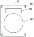
FIG. 19A is a schematic front view of an electric component mounting plate 2b as a part of a mounting portion,
fig. 19B is a schematic side view thereof. As shown in fig. 19, a vital sensor (not shown) for measuring body temperature and pulse is attached to the bottom surface of the electric component mounting plate 2b, and a circuit board 2b1 is disposed on the surface. A fan mounting mechanism 2b2 for detachably mounting the fan is formed, and hooks 2b3 for mounting the backpack belt 79 are formed at the four corners.
Fig. 20 is a schematic front view of the power supply unit. Fig. 21 is a schematic side view of the fan. Fig. 22 is a schematic side view of a unit portion in which a fan having a power supply unit mounted thereon is mounted on the electrical component mounting plate 2 b.
In the present modification, as shown in fig. 20, four power supply units 71a of lithium ion batteries 71a2 are disposed in a square-shaped container 71a1 and are attached to the side surface of a fan 1 c. The inner edge of the power supply portion 71a is in the form of a disc that contacts the cylindrical portion of the fan 1c, and the power supply portion 71a is configured to sandwich the fan opening hole between the lower surface of the flange 75 of the fan 1c and the upper surface of the power supply portion 71a while taking into account the function of the attachment ring, as in the case of the relationship between the fan and the attachment ring of the conventional air-conditioning garment (see japanese patent application laid-open No. 2015-065998). However, the fan 1c is fixed to the electrical component mounting plate 2b by the fan attachment mechanism, and does not apply a load to the fan opening hole. The structure of the fan 1c on the side of the power supply unit 71a to which the power supply unit 71a is attached is a power supply unit attachment mechanism. Further, since power supply portion 71a is attached in a square shape to the cylindrical portion surrounding propeller fan FN11a, power supply portion 71a is significant in terms of securing an attachment location without disturbing the flow of air from air sending portion 73.
Next, the electrical connection of the cell portions will be explained. Two electrodes (not shown) are disposed in the cylindrical portion of the fan 1c at the portion where the power supply portion 71a is attached, and when the power supply portion 71a is attached to the fan 1c, the two electrodes (not shown) provided in the power supply portion 71a are in contact with the electrodes of the cylindrical portion, and are connected to a power supply bottom electrode (not shown) provided in the bottom of the fan 1c via power cables (not shown) attached to the two electrodes of the fan 1 c. The motor FN11b is connected to a motor bottom electrode (not shown) via a two-pole power cable (not shown).
When the fan 1c having the power supply unit 71a mounted thereon is mounted on the electrical component mounting plate 2b, the power supply bottom electrode and the fan bottom electrode are brought into contact with electrodes (not shown) provided on the circuit board and corresponding to the respective electrodes, and the electric power from the power supply unit 71a is converted into appropriate voltages via the respective circuits provided on the circuit board 2b1 and applied to the motor FN11 b.
Fig. 23 is a circuit block diagram. On the circuit board 2b1, there are disposed: a voltage conversion circuit 2b11 that converts the voltage of the power supply section 71a based on the instruction of the control circuit 2b12 and applies the converted voltage to the motor FN11b of the fan 1 c; and a communication circuit 2b13 that transmits information such as the vital sensor BS and the temperature/humidity sensor TS to an external communication device (not shown) such as a smartphone and receives instructions from the external communication device. Therefore, an appropriate voltage is supplied to the motor FN11b based on the temperature and humidity of the introduced air and the data of the life sensor BS. Further, an appropriate voltage can be supplied to the motor FN11b based on an instruction from the outside.
Next, an example of a procedure for wearing the air-conditioning garment according to the present modification will be described. Fig. 24A is a schematic front view and fig. 24B is a schematic rear view of the air-conditioning garment according to the modification. Further, the fan opening 53 is provided on the back of the air-conditioning garment body, and as shown in fig. 24, an air discharge unit 130 is provided at a different position of the garment body 5 in addition to the neckline and the arm. The band 79 is attached to the electrical component mounting plate 2b in advance.
1 the fan 1c is inserted into the fan opening hole 53 from the outside.
2 the power supply part 71a is inserted from the inside of the garment body 5 so as to be sandwiched between the edges of the fan opening hole 53 and is attached to the body of the fan 1 c.
3 the fan 1c with the power supply portion 71a attached thereto is attached and fixed to the electrical component mounting plate 2 b. Thereby, the unit portion to which the band 79 and the garment main body 5 are attached is completed.
4 bear the unit part.
5 wearing the clothes through the arms and zipping the zipper.
Next, a method of use will be described. Further, software associated with the smartphone, which is an external communication device, is installed.
When the air-conditioning garment is activated by the smartphone, data output from the temperature/humidity sensor TS and the life sensor BS is transmitted to the smartphone, air-blowing amount data calculated based on the data is transmitted to the unit section, and power is applied to the motor FN11b of the fan 1c by the voltage conversion circuit 2b11 under the control of the control circuit 2b12 based on the received air-blowing amount data.
In the present modification, the case where a conventional hand guard is attached to the air intake portion of the fan has been described, but various optional accessories such as those shown in fig. 25A, 25B, and 25C may be attached instead of the hand guard.
Fig. 25A shows an optional container OP1 for the same purpose as in the case of using a filter or a water-containing sponge described in the fourth embodiment described later.
Fig. 25B is a rain cover OP2 for sucking outside air from the lower side so as not to let rainwater in.
Fig. 25C shows a container OP3 in which granular dry ice (coolant) or the like is put.
In this way, the hand guard can be changed from a simple hand guard to a container or the like according to the purpose of use, and the hand guard is carried on the back, so that the hand guard hardly becomes a burden even if the weight of the container, the contents thereof, and the like is considerable.
(fourth embodiment)
Fig. 26 is a schematic sectional view of the unit portion 7b of the fourth embodiment.
The air-conditioning garment of the present embodiment uses the unit 7b as in the third embodiment. As shown in fig. 26, the difference from the third embodiment is that, at the point that the air introduction portion 72 is provided with a functional space 721 and houses a filter 722, the functional space 721 is expanded to the entire upper surface of the unit portion 7b and is used for mounting the filter 722 for purifying dust directly below the air introduction portion. The present embodiment is characterized in that air purified by removing dust and the like from the introduced air by the filter 722 is introduced into the inside of the clothes main body.
(modification example)
The air-conditioning clothes according to the present modification example are air-conditioning clothes that are used in a dry environment where the outside air temperature is very high, such that the air-conditioning clothes cannot be used only by the heat of vaporization of sweat. This modification is a special air-conditioning garment in which air introduced into the air-conditioning garment is cooled by the heat of vaporization of water.
Fig. 27 is a schematic front view of a hydrous sponge 723 functioning as a hydrous mechanism.
This modification is different from the fourth embodiment in that a water-containing sponge 723 is housed instead of the filter 722 housed in the functional space 721. The sponge 723 for water-containing is, for example, applied to the whole surface at an opening ratio of 50% A sponge having pores of 1cm in thickness and having high water absorbability. By storing the water-containing
 sponge 723 after absorbing water in the functional space 721, air passes through the functional space A large amount of water is evaporated at this time, and the air cooled by the vaporization heat is introduced into the inside of the air-conditioning clothes.
The method of cooling air using water and the heat of vaporization of water is not limited to the method using water-containing sponge, and may be, for example, a method in which a mist generator is disposed in a functional space and mist is introduced into air-conditioning clothes. In this case, the container for supplying water may be provided in the functional space or may be provided outside.
In the third and fourth embodiments and the modifications thereof, the case where dust is removed by a filter, the case where cooling is performed by the heat of vaporization of water, and the like have been described, but if necessary, a specific substance or a harmful substance may be removed by various filters or the like, or a deodorant or perfume may be added to a sponge or the like, or a substance useful for the body may be introduced into clothes by various other methods.
As described in the third and fourth embodiments and the modifications thereof, the air improving mechanism for improving the air introduced into the clothes can use various methods according to the purpose (not introducing rainwater is also one of the air improvement). The air improving mechanism is not limited to the method of improving the air taken in by the fan by being disposed outside the fan as in the embodiment, and a method of improving the air taken in by the fan may be used. Therefore, the position where the air improving mechanism is disposed is the periphery of the air introduction port of the fan.
As described above, by fixing the electrical component to the wearing portion, the electrical component can be completely prevented from falling. Further, it is possible to realize an increase in size and functionalization that are difficult for the conventional air-conditioning clothes in which a fan is attached to the clothes. Further, since the unit portion is in close contact with the body, sensors for physical condition management (body surface temperature, pulse, etc.) can be easily attached. Then, by transmitting the data to a work manager or the like, a person with abnormal physical condition can be detected.
(fifth embodiment)
Next, an air conditioning clothing electrical component wearing unit (air conditioning unit) of the fifth embodiment will be described. The air-conditioning clothes electrical component wearing unit of the embodiment comprises: an electrical component mounting belt (a wearing part) 2 described later, and a fan 1d attached to the electrical component mounting belt 2. That is, the electric component mounting unit for air-conditioning clothing according to the first embodiment is different from the electric component attachment unit according to the first embodiment in that the electric component mounted on the electric component mounting belt-like object 2 is only the fan, and the power supply unit and the power supply cable are mounted on the electric component mounting belt-like object 2 in addition to the fan.
Fig. 28 is a schematic view of the electrical component mounting belt 2 constituting the electrical component mounting unit for air-conditioning clothing according to the fifth embodiment. As shown in fig. 28, the electric component mounting strip 2 of the present embodiment includes a strip main body 21, a pair of connection terminals 24 for connection to each other, and a wire locking member (length adjustment mechanism) 25. The belt 22 forming a main part of the belt main body 21 of the present embodiment is constituted by one string having no elasticity. A pair of connection terminals 24 are provided at both ends of the rope. The wire lock 25 fixes the string at a desired length, thereby adjusting the length of the string.
The electric component mounting belt 2 of the present embodiment is worn on the body by connecting the connection terminals 24 to each other in a state where the cord as the belt main body 21 is wound around the body.
Next, the fan 1d constituting the air-conditioning clothing electrical component attachment unit of the present embodiment will be described.
Fig. 29A is a schematic side view of a fan 1d of the present embodiment, fig. 29B is a schematic rear view thereof, and fig. 29C is a schematic rear view of the fan 1d in a state of being attached to a rope.
As shown in fig. 29A to 29C, the fan 1d includes: a main body 10 including a fan body and a cover for housing the fan body; a cylindrical mounting tube portion 17 detachably provided to the main body portion 10; and a fan mounting mechanism 15 for slidably mounting to the cord. The mounting tube portion 17 is a member for fixing the fan 1d mounted to the fan opening hole 53 of the garment body 5. Specifically, as shown in fig. 29A, by attaching the mounting tube 17 to the main body 10 so as to cover the side surface of the main body 10, the edge of the fan opening hole 53 is sandwiched between the flange 12 provided at the upper portion of the main body 10 and the mounting tube 17, and the fan 1d is fixed to the fan opening hole 53.
The fan attachment mechanism 15 is provided at the lower portion of the main body 10, and has an attachment fitting (not shown) having an "Ω" shape at the abutting portion at both ends, and the attachment fitting has elasticity. The attachment fitting is configured to be easily attached and detached by a person in a slidable manner, but cannot be easily detached naturally. Thus, the fan attachment mechanism 15 is attached to the electric component attachment belt 2 so as to be movable in the longitudinal direction of the cord. The fan mounting mechanism 15 is mounted to the electrical component mounting belt-like object 2 so as to be slidable on the electrical component mounting belt-like object 2. The above-described configuration of the fan mounting mechanism 15 can be simply realized by various methods by utilizing the elasticity of the mounting metal member, and thus detailed description is omitted. Instead of the metal fitting, an elastic plastic molded product in the shape of "Ω" may be used.
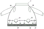
Next, a method of using the air-conditioning garment to which the air-conditioning garment electrical component attachment unit of the present embodiment is attached will be described. Fig. 30 is a schematic front view of the air-conditioning garment in a state in which the air-conditioning garment electrical component attachment unit according to the present embodiment is attached and in a state in which the front body is open.
First, the two fans 1d and 1d are attached to the fan opening hole 53 of the garment body 5, respectively. As described above, the edge of the fan opening hole 53 is sandwiched between the flange 12 provided at the upper portion of the main body 10 and the mounting cylindrical portion 17, whereby the fan 1d is fixed to the fan opening hole 53. That is, the flange 12 of the fan 1d and the mounting cylindrical portion 17 form a fan-side coupling portion. Further, the details of the mounting method are disclosed in Japanese patent application 2016-.
Next, the fan 1d and a power supply unit (not shown) are connected via a power cable (not shown).
Subsequently, as shown in fig. 29C and 30, the rope is attached to the fan attachment mechanism 15 of the fan 1d, and the garment main body 5 is put on. Then, the pair of connection terminals 24 provided on the string are connected to each other, and the electric component mounting belt 2 is worn on the waist. Further, the length of the string is adjusted by the wire lock 25 as necessary.
Next, the zipper 58 provided on the front part of the garment body 5 is zipped. Then, the fan 1d is driven to introduce outside air into the clothes.
(sixth embodiment)
Next, an air-conditioning garment according to a sixth embodiment will be described.
Fig. 31A is a schematic front view of the garment body 5 of the air-conditioning garment of the present embodiment, and fig. 31B is a schematic cross-sectional view of the waist portion to which the fan 1d is attached when the garment body 5 is worn with the fan 1d attached.
In the fifth embodiment, the fan attachment means 15 is provided as attachment fittings on the left and right sides of the main body 10 of the fan 1d, and the string is threaded through the attachment fittings, but in the present embodiment, as shown in fig. 31A, instead of attaching the attachment fittings to the fan 1d, the thread passing means 59 is attached to the cloth 51 in the vicinity of the left and right sides of the fan 1d, and a string (rubber string) is threaded therethrough as the belt 22 which is the main part of the belt main body. Further, the column of the air sending part of the fan 1d is coupled to the string via a hook (not shown). Then, both ends of the string are sewn to the vicinity of the zipper of the garment body 5 via the interval securing mechanism 57. That is, the fan 1d is not directly brought into close contact with the body by the string, but the fan 1d is pressed against the body through the clothing 51 so as to be substantially perpendicular to the body, thereby bringing the fan 1d into close contact with the body. Thus, the cord is completely built in the clothes, and the existing fan can be used as it is.
With such a configuration, as shown in fig. 31B, when the slide fastener 58 of the coat garment main body 5 is pulled for use, the fan 1d is in close contact with the body. Further, since the fan 1d is pressed against the body (the trunk BD), the force for winding the string around the body can be reduced. Further, by using a rubber string for a part or the whole of the string, it is possible to absorb the difference in diameter of the trunk, and thus it is not necessary to adjust the length of the string.
Further, since the column of the air sending part of the fan 1d is coupled to the string by a hook (not shown), the fan 1d can be prevented from dropping when the fan 1d is detached from the garment body 5. In this case, the mechanism for coupling the fan 1d and the string can be regarded as the fan attachment mechanism by coupling the fan 1d to the string with a hook or the like. The method of mounting the fan 1d to the rope is not limited to the method using the hook, and various general methods can be used.
As described above, according to the air-conditioning clothing electrical component attachment unit of the first, second, fifth, and sixth embodiments, even when the air-conditioning clothing is used and the inside of the clothing is a positive pressure, the fan is attached to the electrical component attachment belt worn on the user, and therefore, the portion of the fan does not swell. Therefore, various problems (for example, an operation of preventing the air-conditioning clothes from being worn) caused by the swelling of the fan can be avoided.
Further, the conventional air-conditioning clothes have the following advantages that the fan is attached to the clothes main body in a suspended state, and the air-conditioning clothes using the air-conditioning clothes electrical component attachment unit according to each embodiment have the fan in close contact with the body.
1, even if an external force is applied to the fan, since the fan device is in close contact with the body, the fan device does not move greatly, and thus, a large impact force is not applied to the internal components of the fan, and inexpensive components having a small impact resistance can be used. Further, since the external force applied to the fan is absorbed by the body, inexpensive materials can be used for the structural members constituting the fan.
2 obtaining the air-conditioning clothing electrical component wearing unit enables individual clothing to be easily processed into a clothing body for air-conditioning clothing, and therefore, the popularization of air-conditioning clothing can be accelerated and the environment-friendly society can be promoted.
In addition, although the case where one string having no elasticity is used as the string-shaped object main body in the fifth embodiment and one rubber string is used in the sixth embodiment is described, the string-shaped object used in the fifth and sixth embodiments may be a string-shaped object in which a part or the whole of the string-shaped object is composed of one or a plurality of strings, one or a plurality of bands, or a combination of one or a plurality of strings and one or a plurality of bands. In particular, in the sixth embodiment, various combinations can be used, such as providing the threading mechanism in the upper and lower vicinity of the fan opening hole and providing two strings in the vicinity of the fan.
In addition, a part or the whole of the string is made elastic by using a rubber string or the like, and thus a wire locking member for adjusting the length of the string can be omitted.
Further, both ends of the belt-like object main body may be attached to the vicinity of the slide fastener without using the connection terminals. In addition, in the case of attaching the band-like object, instead of sewing, hooks or the like may be attached to both ends of the band-like object main body, and an engaging mechanism for engaging with the hooks or the like may be provided in the vicinity of the slide fastener to detachably attach the band-like object main body to the clothing main body. The attachment position is not limited to the vicinity of the zipper, and may be the front side of the garment body. In this case, the portion from one point to the other point where the end of the string is attached can be regarded as a part of the belt-like object main body including the slide fastener (opening/closing mechanism). In this way, the fan is worn by putting on the clothes with both ends of the string attached to the front side of the clothes main body and zipping the zipper.
In the first, fifth, and sixth embodiments, the fan can be attached to the fan opening hole from the inside of the garment, and therefore, as shown in fig. 32, a directly connected and integrated component can be used for the fan and the power cable 4. In this way, by integrating the fan and the cable and removing the terminal portion, it is possible to eliminate the contact failure and to reduce the cost.
In the third and fourth embodiments, the air-conditioning clothing electrical component attachment unit is integrated with all the electrical components as a unit section, and in the first, second, fifth, and sixth embodiments, the fan is attached to the belt-like body as the attachment means, and therefore, the fan does not fall off even when the fan falls off from the clothing body. Further, since the fan is supported by the belt body, the weight of the fan can be suppressed from being applied to the garment body, and the air-conditioning garment can be made to have a good wearing feeling.
Further, according to the air-conditioning clothing electrical component attachment unit of the fifth and sixth embodiments, the fan is slidably attached to the belt-like object, and therefore, even when there is a variation in the arrangement of the fan opening holes, the fan can be easily attached to the fan opening hole by sliding the position of the fan. In the fifth embodiment, the length of the electric component mounting belt can be adjusted by providing the wire lock, and in the sixth embodiment, the fan can be brought into close contact with the body with a reasonable pressure because the belt has elasticity.
In addition, according to the air-conditioning clothing electrical component wearing unit of the first to fifth embodiments, by separating the clothing main body mainly made of the sheet material and the electrical component made of a material completely different from the sheet material, it is almost unnecessary to consider the relationship between both. Therefore, the clothing main body can be designed and manufactured reasonably as a clothing product and the unitized electric components can be designed and manufactured as an electric product, thereby achieving cost reduction, performance improvement and convenience improvement.
In the first and second embodiments, the case where the electric component attachment band is wrapped around the abdomen and worn on the body has been described, but the electric component attachment band may be attached to the body, for example, by being worn from the shoulder or the neck.
In the embodiments, the case of the upper body wearing the jacket has been described with respect to the garment body, but the lower body may be covered as in a coverall or a winter coat. In this case, the air leakage prevention mechanism of the skirt is not essential.
As a specific power source used for the power source unit, a primary battery, a secondary battery, and a fuel cell can be used. In the case of using a solar cell (solar panel), the solar panel itself cannot be housed in the power supply unit, but a mechanism for using or storing electricity generated by the solar panel is the power supply unit.
The shape of the fan is not limited to a circular shape. For example, the fan is not limited to a so-called propeller fan, and may be a multi-blade fan (radiator fan). Further, the air introducing portion is not limited to be opened on the upper surface according to the shape of the fan and the like.
In the embodiments, the case where two fans are used on the left and right sides and the case where one large fan is used have been described, but the number of fans may be two or more.
The power supply unit and the like may be provided with a communication means for operating the on/off of the fan and/or the rotation speed of the fan based on an instruction received from an external device, for example, a program of a smartphone.
Further, the fan control device may include a measurement unit that measures vital signs such as body temperature and pulse, and control the on/off of the fan and/or the rotation speed of the fan based on the measurement result of the measurement unit. Further, the communication means may be controlled to transmit the measurement result of the measurement means to the outside.
Further, the measurement result of the measurement means may be transmitted to a smartphone, which is an external device, and the on/off of the fan and/or the rotation speed of the fan may be operated based on an instruction based on the measurement result received from the application of the smartphone.
In the fifth and sixth embodiments, the case where the fan 1d is slidably attached to the electrical component mounting strip 2 is exemplified, but the fan 1d is not necessarily slidably attached. For example, as shown in fig. 33, the electric component mounting belt 2 may be configured by tying a string constituting the belt main body 21 to both side portions of the fan 1 d. That is, in this case, the fan 1d can be regarded as a part of the electrical component mounting belt 2.
In the fifth embodiment and the above-described embodiments, the case where the fan 1d is slidably attached to the electrical component mounting strip 2 is exemplified, but the method of slidably attaching the fan 1d to the electrical component mounting strip 2 is not limited to the exemplified method in each embodiment, and various general methods can be adopted.
The position of the fan 1d may be changed as appropriate, and may be arranged on the front side of the garment body 5, not on the back side. In this case, when the user sits on a chair or a car seat, the fan 1b does not become an obstacle, and the air flow passage can be ensured between the clothes and the back even when the user leans against the back of the chair by disposing the spacer disclosed in patent No. 4067034 on the inner surface of the back of the clothes.
In the fifth and sixth embodiments, the case where the electric component mounted on the electric component mounting belt-like object 2 is only a fan is illustrated, but a power supply unit (power supply) as an electric component may be mounted on the electric component mounting belt-like object 2 for the purpose of preventing the electric component from falling.
In each embodiment, a mechanism for adjusting air discharge resistance may be provided in the air discharge portion. For example, in the case of using a half-sleeve as the garment body, in order to optimize the ratio of air discharge based on the relationship between the arm thickness and the sleeve, the opening degree of the half-sleeve may be adjusted by a button (for example, a snap button) B disposed at the cuff as shown in fig. 34A. Further, as shown in fig. 34B, a rectangular region R near the rear collar may be provided with a slack or a spacer to secure the air discharge amount from the rear collar. The mechanism for adjusting the air discharge resistance of each air discharge unit is not limited to the above, and various general methods can be used.
The present invention is not limited to the embodiments, and various improvements and design changes can be made without departing from the scope of the present invention.
The present invention can be suitably used in the field of manufacturing air-conditioning clothes.
Description of the figures
100. 100a, 100b, 100c … air-conditioning clothing electrical component wearing unit; 1. 1a, 1b, 1c, 1d … fan; 10 … a body portion; 11 … air intake; 12 … a flange; 121 … upper flange; 122 … lower flange; 14 … air delivery part; 15 … fan mounting mechanism; 16 … tubular connection part (fan-side connection part); 161 … groove; 17 … installing a barrel part; 2. 2a … electric component mounting belt (mounting part); 21. 21a … belt body (wearing mechanism); 22 … a ribbon; 23 … installing an adjusting mechanism; 24 … connection terminal; 25 … wire lock (length adjustment mechanism); 3 … power supply part; 31 … power supply unit mounting mechanism; 4 … power supply cables; 5. 5a, 5c, 5d … garment body; 51 … clothing material; 52 … collar; 53 … open hole for fan; 54 … lower hem threading mechanism; 57 … space ensuring mechanism; 58 … opening and closing mechanism (zipper); 59 … threading mechanism; 6. 6a … elastic ring (connection auxiliary); 7. 7a, 7b … cell parts; 71 … a power supply section; 72 … air intake; 721 … functional space; 722 … filter; 723 … sponge for water (water containing mechanism); 73 … air delivery part; 74 … tubular coupling portion (coupling portion); 75 … flanges; 76 … cell fixing mechanism; 77 … grooves; 78 … an angled guide; 79 … belts (wearing mechanisms); 101 … air conditioning clothing; 110 … a garment body; 130 … air exhaust; 140 … fan; k1 … is inserted into the fitting part; a k11 … plug; k12 … fitting spring; k13 … engaging the wall; k2 … inserted and embedded part; a k21 … socket; k22 … engaging the wall; k3 … waistband; k4 … neck strap; a k5 … hook; 2b … electric parts wearing plate; 2b1 … circuit substrate; 2b2 … fan mounting mechanism; 2b3 … hook; an FN11 … fan body; CV11 … cover.
Claims (7)
1. An electrical component wearing unit for air-conditioning clothes, which is used in combination with a sheet-like raw material having an opening hole for a fan,
the air-conditioning clothing electrical component wearing unit is provided with a fan, and a power supply unit and a power supply cable for supplying power to the fan,
the fan includes a fan body, a cover portion for housing the fan body, and a cylindrical coupling portion for coupling the fan and the fan opening hole,
the tubular coupling portion has an air introduction side and an air discharge side, the tubular coupling portion has a flange having a groove on the air introduction side,
an opening edge portion of the sheet material having the opening hole for the fan is fitted into the groove.
2. The electrical component wearing unit for air-conditioning clothing according to claim 1,
the sheet stock material is stretchable.
3. The electrical component wearing unit for air-conditioning clothing according to claim 1 or 2,
the flange has an upper flange and a lower flange, and the slot is formed between the upper flange and the lower flange.
4. The electrical component wearing unit for air-conditioning clothing according to claim 3,
the outer diameter of the upper flange is smaller than the outer diameter of the lower flange.
5. The air-conditioning clothing electrical component wearing unit according to any one of claims 1 to 4,
the air-conditioning clothing electrical component wearing unit is provided with at least a wearing mechanism for wearing the fan on the body.
6. The air-conditioning clothing electrical component wearing unit according to any one of claims 1 to 5,
the fan is provided with a movable mechanism which enables the fan to move on the wearing mechanism.
7. An air-conditioning garment is characterized in that,
the air-conditioning garment is used in combination with the electrical component wearing unit for air-conditioning garments according to any one of claims 1 to 6.
Applications Claiming Priority (7)
| Application Number | Priority Date | Filing Date | Title |
|---|---|---|---|
| JP2016045100 | 2016-03-09 | ||
| JP2016-045100 | 2016-03-09 | ||
| JP2016-099407 | 2016-05-18 | ||
| JP2016099407 | 2016-05-18 | ||
| JP2017-007146 | 2017-01-19 | ||
| JP2017007146 | 2017-01-19 | ||
| CN201780015113.0A CN108778013B (en) | 2016-03-09 | 2017-03-08 | electric component wearing unit for air-conditioning clothes and air-conditioning clothes |
Related Parent Applications (1)
| Application Number | Title | Priority Date | Filing Date |
|---|---|---|---|
| CN201780015113.0A Division CN108778013B (en) | 2016-03-09 | 2017-03-08 | electric component wearing unit for air-conditioning clothes and air-conditioning clothes |
Publications (1)
| Publication Number | Publication Date |
|---|---|
| CN110897226A true CN110897226A (en) | 2020-03-24 |
Family
ID=59790552
Family Applications (2)
| Application Number | Title | Priority Date | Filing Date |
|---|---|---|---|
| CN201911127239.4A Pending CN110897226A (en) | 2016-03-09 | 2017-03-08 | Electric component wearing unit for air-conditioning clothes and air-conditioning clothes |
| CN201780015113.0A Active CN108778013B (en) | 2016-03-09 | 2017-03-08 | electric component wearing unit for air-conditioning clothes and air-conditioning clothes |
Family Applications After (1)
| Application Number | Title | Priority Date | Filing Date |
|---|---|---|---|
| CN201780015113.0A Active CN108778013B (en) | 2016-03-09 | 2017-03-08 | electric component wearing unit for air-conditioning clothes and air-conditioning clothes |
Country Status (4)
| Country | Link |
|---|---|
| US (1) | US11571028B2 (en) |
| JP (4) | JP6445216B2 (en) |
| CN (2) | CN110897226A (en) |
| WO (1) | WO2017154961A1 (en) |
Families Citing this family (22)
| Publication number | Priority date | Publication date | Assignee | Title |
|---|---|---|---|---|
| US20180220721A1 (en) * | 2017-02-08 | 2018-08-09 | Francis Houde | Self-Cooling Garment System and Method of Using the Same |
| JP7031837B2 (en) * | 2017-05-12 | 2022-03-08 | 株式会社セフト研究所 | Power supply for air-conditioned clothes and air-conditioned clothes |
| RU2741524C1 (en) * | 2017-10-09 | 2021-01-26 | Бейджинг Мкс Рисёрч Инститьют | Device for fast inflating and blowing of protective clothes and intelligent universal protective clothing containing such device |
| JP7117762B2 (en) * | 2017-10-11 | 2022-08-15 | 山真製鋸株式会社 | cooling garment blower, cooling garment blower unit and cooling garment |
| JP7134706B2 (en) * | 2018-05-18 | 2022-09-12 | 株式会社クラレ | wearable body cooling device |
| US11918060B2 (en) * | 2018-10-17 | 2024-03-05 | Kabushiki Kaisha Acb | Blower for air-conditioned garment and air-conditioned garment |
| JP6590231B1 (en) * | 2019-04-04 | 2019-10-16 | 株式会社Acb | Air conditioner clothes blower |
| JP6528069B1 (en) * | 2018-10-17 | 2019-06-12 | 株式会社Acb | Air conditioning clothes blower and air conditioning clothes. |
| JP6971479B2 (en) * | 2018-12-18 | 2021-11-24 | 有限会社太伸エンジニアリング | Manufacturing method of body cooler and body cooler |
| JP6631981B2 (en) * | 2019-01-22 | 2020-01-15 | 株式会社マキタ | Blowers and clothes |
| JP6596604B1 (en) * | 2019-02-20 | 2019-10-23 | ファンテック株式会社 | Air conditioner fan unit |
| JP2020172899A (en) * | 2019-04-11 | 2020-10-22 | クロダルマ株式会社 | cooling fan |
| JP6878706B2 (en) * | 2019-05-20 | 2021-06-02 | 京セラインダストリアルツールズ株式会社 | Clothes fan and garment with fan |
| JP2021008687A (en) * | 2019-06-28 | 2021-01-28 | シキボウ株式会社 | Perfume component for garment with fan |
| WO2021033244A1 (en) * | 2019-08-19 | 2021-02-25 | ファンテック株式会社 | Ringed contra-rotating propeller fan unit for air-conditioned clothing |
| JP2021102923A (en) * | 2019-12-24 | 2021-07-15 | 株式会社ブレイン | Fan for clothing and clothing with fan |
| JP1678593S (en) * | 2020-04-02 | 2021-02-08 | ||
| KR102215726B1 (en) * | 2020-05-18 | 2021-02-18 | 프린텍 주식회사 | Neck band fan |
| JP7339228B2 (en) * | 2020-11-10 | 2023-09-05 | トヨタ自動車株式会社 | air conditioning garment |
| KR102345281B1 (en) * | 2020-12-01 | 2021-12-30 | 주식회사 투인리브 | Cooling apparatus with air pocket |
| WO2022174231A1 (en) * | 2021-02-09 | 2022-08-18 | Marc Richelsoph | Adaptive temperature control system for garments and methods for controlling temperature of garments |
| JP7422446B1 (en) | 2023-10-05 | 2024-01-26 | 株式会社リブレ | Clothing mounting structure for body temperature adjustment device and body temperature adjustment clothing |
Citations (9)
| Publication number | Priority date | Publication date | Assignee | Title |
|---|---|---|---|---|
| CN1087020A (en) * | 1992-11-16 | 1994-05-25 | 周立新 | The medicinal health-care belt in magnetic field can rotate |
| CN2616084Y (en) * | 2003-04-16 | 2004-05-19 | 王宝顺 | Summer-cold waistband device for garment |
| CN1627904A (en) * | 2002-06-07 | 2005-06-15 | 株式会社斯福特开发研究所 | Cooled clothes |
| CN2798637Y (en) * | 2005-05-19 | 2006-07-26 | 袁丽萍 | Cooling clothes |
| CN101046207A (en) * | 2006-11-29 | 2007-10-03 | 郭静 | Miniature fan on waist belt |
| CN100393256C (en) * | 2003-08-01 | 2008-06-11 | 斯福特开发研究所股份有限公司 | Cooling clothes |
| CN201384093Y (en) * | 2009-03-31 | 2010-01-20 | 王君超 | Belt bag |
| CN202941464U (en) * | 2012-06-25 | 2013-05-22 | 中国人民解放军海军医学研究所 | Dive waistband |
| CN204599377U (en) * | 2015-05-04 | 2015-09-02 | 周莎 | A kind of work clothes of Novel belt fan |
Family Cites Families (22)
| Publication number | Priority date | Publication date | Assignee | Title |
|---|---|---|---|---|
| JPS6430308U (en) * | 1987-08-17 | 1989-02-23 | ||
| FR2848291B1 (en) * | 2002-12-06 | 2005-02-04 | Delta Prot | VENTILATION BLOCK FOR GARMENT AS A SCAPHANDRE OR THE LIKE |
| JP4399765B2 (en) * | 2003-06-26 | 2010-01-20 | 株式会社セフト研究所 | Fan mounting device for fan-exposed air-conditioning clothing and blower device for fan-exposed air-conditioning clothing |
| JP2005029914A (en) | 2003-07-09 | 2005-02-03 | Yoshihiro Sakaida | Ventilating garment |
| WO2005063065A1 (en) * | 2003-12-25 | 2005-07-14 | Seft Development Laboratory Co.,Ltd. | Air-conditioned garment |
| JPWO2006009108A1 (en) | 2004-07-21 | 2008-05-01 | 株式会社セフト研究所 | Air-conditioning clothing |
| JP2006132040A (en) | 2004-11-08 | 2006-05-25 | Seft Dev Lab Co Ltd | Air-conditioning clothing |
| JP4872293B2 (en) * | 2004-12-24 | 2012-02-08 | 株式会社デンソー | Centrifugal multiblade blower |
| WO2006077876A1 (en) * | 2005-01-21 | 2006-07-27 | Seft Development Laboratory Co., Ltd. | Air-conditioned garment |
| WO2007061088A1 (en) * | 2005-11-28 | 2007-05-31 | Seft Development Laboratory Co., Ltd. | Air-conditioned clothes |
| JP4067034B2 (en) | 2006-02-13 | 2008-03-26 | 株式会社セフト研究所 | Human body spacer, human body airflow passage, and general-purpose spacer |
| US20110048048A1 (en) * | 2009-03-25 | 2011-03-03 | Thomas Gielda | Personal Cooling System |
| US20140090410A1 (en) * | 2012-10-02 | 2014-04-03 | Jeff Decker | Air cooling device |
| CN203058373U (en) * | 2013-01-07 | 2013-07-17 | 蔡思莹 | Cooling and temperature-reducing work clothes |
| JP5672642B1 (en) | 2013-09-26 | 2015-02-18 | 株式会社セフト研究所 | Fan mounting part of sheet-like member and manufacturing method of fan mounting part |
| EP3121452B1 (en) | 2014-03-18 | 2020-03-04 | SFT Laboratory Co., Ltd. | Sheet having fan-mounting part |
| JP2016037959A (en) * | 2014-08-05 | 2016-03-22 | 株式会社プロップ | Blower device for human body |
| DE102014225528A1 (en) * | 2014-12-11 | 2016-06-16 | Robert Bosch Gmbh | Method for controlling a high-pressure pump for fuel injection in an internal combustion engine |
| US9936787B1 (en) * | 2015-07-01 | 2018-04-10 | Djuna S. Jones | Versatile cordless portable hair dryer for direct or bonnet usage on demand |
| CN204930427U (en) * | 2015-07-06 | 2016-01-06 | 江苏师范大学 | A kind of anti-haze jacket |
| CN104921340A (en) * | 2015-07-14 | 2015-09-23 | 爱谱诗(苏州)服装有限公司 | Garment with cooling function |
| CN204907991U (en) * | 2015-07-14 | 2015-12-30 | 嵊州市宏达制衣有限公司 | Fan refrigeration ventilation clothing |
-
2017
- 2017-03-08 WO PCT/JP2017/009179 patent/WO2017154961A1/en active Application Filing
- 2017-03-08 CN CN201911127239.4A patent/CN110897226A/en active Pending
- 2017-03-08 JP JP2018504547A patent/JP6445216B2/en active Active
- 2017-03-08 CN CN201780015113.0A patent/CN108778013B/en active Active
- 2017-03-08 US US16/083,423 patent/US11571028B2/en active Active
-
2018
- 2018-11-28 JP JP2018221850A patent/JP6996749B2/en active Active
-
2021
- 2021-12-09 JP JP2021199696A patent/JP2022022385A/en active Pending
-
2024
- 2024-01-04 JP JP2024000026A patent/JP2024024041A/en active Pending
Patent Citations (9)
| Publication number | Priority date | Publication date | Assignee | Title |
|---|---|---|---|---|
| CN1087020A (en) * | 1992-11-16 | 1994-05-25 | 周立新 | The medicinal health-care belt in magnetic field can rotate |
| CN1627904A (en) * | 2002-06-07 | 2005-06-15 | 株式会社斯福特开发研究所 | Cooled clothes |
| CN2616084Y (en) * | 2003-04-16 | 2004-05-19 | 王宝顺 | Summer-cold waistband device for garment |
| CN100393256C (en) * | 2003-08-01 | 2008-06-11 | 斯福特开发研究所股份有限公司 | Cooling clothes |
| CN2798637Y (en) * | 2005-05-19 | 2006-07-26 | 袁丽萍 | Cooling clothes |
| CN101046207A (en) * | 2006-11-29 | 2007-10-03 | 郭静 | Miniature fan on waist belt |
| CN201384093Y (en) * | 2009-03-31 | 2010-01-20 | 王君超 | Belt bag |
| CN202941464U (en) * | 2012-06-25 | 2013-05-22 | 中国人民解放军海军医学研究所 | Dive waistband |
| CN204599377U (en) * | 2015-05-04 | 2015-09-02 | 周莎 | A kind of work clothes of Novel belt fan |
Also Published As
| Publication number | Publication date |
|---|---|
| JP2022022385A (en) | 2022-02-03 |
| WO2017154961A9 (en) | 2018-03-15 |
| JP6996749B2 (en) | 2022-01-17 |
| JP2024024041A (en) | 2024-02-21 |
| US11571028B2 (en) | 2023-02-07 |
| JP6445216B2 (en) | 2018-12-26 |
| JPWO2017154961A1 (en) | 2018-10-04 |
| WO2017154961A1 (en) | 2017-09-14 |
| CN108778013B (en) | 2019-12-17 |
| US20190239578A1 (en) | 2019-08-08 |
| CN108778013A (en) | 2018-11-09 |
| JP2019039131A (en) | 2019-03-14 |
Similar Documents
| Publication | Publication Date | Title |
|---|---|---|
| CN108778013B (en) | electric component wearing unit for air-conditioning clothes and air-conditioning clothes | |
| CN111629620B (en) | Clothes | |
| US20100242147A1 (en) | Garment for personal air-conditioning | |
| CN208837135U (en) | Air-adjustable equipment and air-adjustable clothes | |
| US11832660B2 (en) | Garment having an internal airflow space between inner and outer fabrics and a separate heat insulation material in the internal airflow space | |
| JP2017133121A (en) | Working garment with air-conditioning device | |
| US20210137181A1 (en) | Cooling apparel | |
| CN111972747A (en) | Positive pressure wearable protective device | |
| US20180220721A1 (en) | Self-Cooling Garment System and Method of Using the Same | |
| CN112203543B (en) | Accessory for clothes and clothes | |
| CN214050233U (en) | Ventilation structure and protective clothing of protective clothing | |
| CN212212738U (en) | Portable clothing intelligence thermostated instrument | |
| CN207190938U (en) | A kind of Novel baggage carrier of automobile | |
| CN113142700A (en) | Clothes with air-purifying and air-conditioning functions | |
| CN216821880U (en) | Semiconductor refrigeration clothing | |
| US20230157382A1 (en) | Garment body of fan-equipped garment and fan-equipped garment | |
| WO2021215395A1 (en) | Charging device and fan-equipped garment | |
| CN216627542U (en) | Whole body protection device with fresh air filtering and air conditioning functions | |
| CN214179217U (en) | Wearable cool fabric and fabric structure thereof | |
| CN215649360U (en) | Novel functional garment | |
| CN209898323U (en) | Heat dissipation type prevents bee clothing | |
| CN212728936U (en) | Positive pressure wearable protective device | |
| CN219026409U (en) | Welding machine bag | |
| JP3232872U (en) | Air conditioning clothing | |
| CN218400826U (en) | Air conditioning device, riding clothes and riding vehicle |
Legal Events
| Date | Code | Title | Description |
|---|---|---|---|
| PB01 | Publication | ||
| PB01 | Publication | ||
| SE01 | Entry into force of request for substantive examination | ||
| SE01 | Entry into force of request for substantive examination |