CN110891762A - Additive manufacturing with vibration isolation interface - Google Patents
Additive manufacturing with vibration isolation interface Download PDFInfo
- Publication number
- CN110891762A CN110891762A CN201780092830.3A CN201780092830A CN110891762A CN 110891762 A CN110891762 A CN 110891762A CN 201780092830 A CN201780092830 A CN 201780092830A CN 110891762 A CN110891762 A CN 110891762A
- Authority
- CN
- China
- Prior art keywords
- vibrating
- bed
- additive manufacturing
- frame
- build
- Prior art date
- Legal status (The legal status is an assumption and is not a legal conclusion. Google has not performed a legal analysis and makes no representation as to the accuracy of the status listed.)
- Pending
Links
Images

Classifications
-
- B—PERFORMING OPERATIONS; TRANSPORTING
- B29—WORKING OF PLASTICS; WORKING OF SUBSTANCES IN A PLASTIC STATE IN GENERAL
- B29C—SHAPING OR JOINING OF PLASTICS; SHAPING OF MATERIAL IN A PLASTIC STATE, NOT OTHERWISE PROVIDED FOR; AFTER-TREATMENT OF THE SHAPED PRODUCTS, e.g. REPAIRING
- B29C64/00—Additive manufacturing, i.e. manufacturing of three-dimensional [3D] objects by additive deposition, additive agglomeration or additive layering, e.g. by 3D printing, stereolithography or selective laser sintering
- B29C64/20—Apparatus for additive manufacturing; Details thereof or accessories therefor
- B29C64/245—Platforms or substrates
-
- B—PERFORMING OPERATIONS; TRANSPORTING
- B29—WORKING OF PLASTICS; WORKING OF SUBSTANCES IN A PLASTIC STATE IN GENERAL
- B29C—SHAPING OR JOINING OF PLASTICS; SHAPING OF MATERIAL IN A PLASTIC STATE, NOT OTHERWISE PROVIDED FOR; AFTER-TREATMENT OF THE SHAPED PRODUCTS, e.g. REPAIRING
- B29C64/00—Additive manufacturing, i.e. manufacturing of three-dimensional [3D] objects by additive deposition, additive agglomeration or additive layering, e.g. by 3D printing, stereolithography or selective laser sintering
- B29C64/10—Processes of additive manufacturing
- B29C64/165—Processes of additive manufacturing using a combination of solid and fluid materials, e.g. a powder selectively bound by a liquid binder, catalyst, inhibitor or energy absorber
-
- B—PERFORMING OPERATIONS; TRANSPORTING
- B29—WORKING OF PLASTICS; WORKING OF SUBSTANCES IN A PLASTIC STATE IN GENERAL
- B29C—SHAPING OR JOINING OF PLASTICS; SHAPING OF MATERIAL IN A PLASTIC STATE, NOT OTHERWISE PROVIDED FOR; AFTER-TREATMENT OF THE SHAPED PRODUCTS, e.g. REPAIRING
- B29C64/00—Additive manufacturing, i.e. manufacturing of three-dimensional [3D] objects by additive deposition, additive agglomeration or additive layering, e.g. by 3D printing, stereolithography or selective laser sintering
- B29C64/20—Apparatus for additive manufacturing; Details thereof or accessories therefor
- B29C64/25—Housings, e.g. machine housings
-
- B—PERFORMING OPERATIONS; TRANSPORTING
- B29—WORKING OF PLASTICS; WORKING OF SUBSTANCES IN A PLASTIC STATE IN GENERAL
- B29C—SHAPING OR JOINING OF PLASTICS; SHAPING OF MATERIAL IN A PLASTIC STATE, NOT OTHERWISE PROVIDED FOR; AFTER-TREATMENT OF THE SHAPED PRODUCTS, e.g. REPAIRING
- B29C64/00—Additive manufacturing, i.e. manufacturing of three-dimensional [3D] objects by additive deposition, additive agglomeration or additive layering, e.g. by 3D printing, stereolithography or selective laser sintering
- B29C64/30—Auxiliary operations or equipment
- B29C64/35—Cleaning
-
- B—PERFORMING OPERATIONS; TRANSPORTING
- B33—ADDITIVE MANUFACTURING TECHNOLOGY
- B33Y—ADDITIVE MANUFACTURING, i.e. MANUFACTURING OF THREE-DIMENSIONAL [3-D] OBJECTS BY ADDITIVE DEPOSITION, ADDITIVE AGGLOMERATION OR ADDITIVE LAYERING, e.g. BY 3-D PRINTING, STEREOLITHOGRAPHY OR SELECTIVE LASER SINTERING
- B33Y30/00—Apparatus for additive manufacturing; Details thereof or accessories therefor
-
- B—PERFORMING OPERATIONS; TRANSPORTING
- B33—ADDITIVE MANUFACTURING TECHNOLOGY
- B33Y—ADDITIVE MANUFACTURING, i.e. MANUFACTURING OF THREE-DIMENSIONAL [3-D] OBJECTS BY ADDITIVE DEPOSITION, ADDITIVE AGGLOMERATION OR ADDITIVE LAYERING, e.g. BY 3-D PRINTING, STEREOLITHOGRAPHY OR SELECTIVE LASER SINTERING
- B33Y40/00—Auxiliary operations or equipment, e.g. for material handling
-
- B—PERFORMING OPERATIONS; TRANSPORTING
- B22—CASTING; POWDER METALLURGY
- B22F—WORKING METALLIC POWDER; MANUFACTURE OF ARTICLES FROM METALLIC POWDER; MAKING METALLIC POWDER; APPARATUS OR DEVICES SPECIALLY ADAPTED FOR METALLIC POWDER
- B22F10/00—Additive manufacturing of workpieces or articles from metallic powder
- B22F10/10—Formation of a green body
- B22F10/14—Formation of a green body by jetting of binder onto a bed of metal powder
-
- B—PERFORMING OPERATIONS; TRANSPORTING
- B22—CASTING; POWDER METALLURGY
- B22F—WORKING METALLIC POWDER; MANUFACTURE OF ARTICLES FROM METALLIC POWDER; MAKING METALLIC POWDER; APPARATUS OR DEVICES SPECIALLY ADAPTED FOR METALLIC POWDER
- B22F10/00—Additive manufacturing of workpieces or articles from metallic powder
- B22F10/60—Treatment of workpieces or articles after build-up
- B22F10/68—Cleaning or washing
-
- B—PERFORMING OPERATIONS; TRANSPORTING
- B22—CASTING; POWDER METALLURGY
- B22F—WORKING METALLIC POWDER; MANUFACTURE OF ARTICLES FROM METALLIC POWDER; MAKING METALLIC POWDER; APPARATUS OR DEVICES SPECIALLY ADAPTED FOR METALLIC POWDER
- B22F10/00—Additive manufacturing of workpieces or articles from metallic powder
- B22F10/70—Recycling
- B22F10/73—Recycling of powder
-
- B—PERFORMING OPERATIONS; TRANSPORTING
- B22—CASTING; POWDER METALLURGY
- B22F—WORKING METALLIC POWDER; MANUFACTURE OF ARTICLES FROM METALLIC POWDER; MAKING METALLIC POWDER; APPARATUS OR DEVICES SPECIALLY ADAPTED FOR METALLIC POWDER
- B22F12/00—Apparatus or devices specially adapted for additive manufacturing; Auxiliary means for additive manufacturing; Combinations of additive manufacturing apparatus or devices with other processing apparatus or devices
- B22F12/30—Platforms or substrates
-
- B—PERFORMING OPERATIONS; TRANSPORTING
- B22—CASTING; POWDER METALLURGY
- B22F—WORKING METALLIC POWDER; MANUFACTURE OF ARTICLES FROM METALLIC POWDER; MAKING METALLIC POWDER; APPARATUS OR DEVICES SPECIALLY ADAPTED FOR METALLIC POWDER
- B22F12/00—Apparatus or devices specially adapted for additive manufacturing; Auxiliary means for additive manufacturing; Combinations of additive manufacturing apparatus or devices with other processing apparatus or devices
- B22F12/38—Housings, e.g. machine housings
-
- B—PERFORMING OPERATIONS; TRANSPORTING
- B22—CASTING; POWDER METALLURGY
- B22F—WORKING METALLIC POWDER; MANUFACTURE OF ARTICLES FROM METALLIC POWDER; MAKING METALLIC POWDER; APPARATUS OR DEVICES SPECIALLY ADAPTED FOR METALLIC POWDER
- B22F2999/00—Aspects linked to processes or compositions used in powder metallurgy
-
- B—PERFORMING OPERATIONS; TRANSPORTING
- B29—WORKING OF PLASTICS; WORKING OF SUBSTANCES IN A PLASTIC STATE IN GENERAL
- B29C—SHAPING OR JOINING OF PLASTICS; SHAPING OF MATERIAL IN A PLASTIC STATE, NOT OTHERWISE PROVIDED FOR; AFTER-TREATMENT OF THE SHAPED PRODUCTS, e.g. REPAIRING
- B29C64/00—Additive manufacturing, i.e. manufacturing of three-dimensional [3D] objects by additive deposition, additive agglomeration or additive layering, e.g. by 3D printing, stereolithography or selective laser sintering
- B29C64/10—Processes of additive manufacturing
- B29C64/141—Processes of additive manufacturing using only solid materials
- B29C64/153—Processes of additive manufacturing using only solid materials using layers of powder being selectively joined, e.g. by selective laser sintering or melting
-
- B—PERFORMING OPERATIONS; TRANSPORTING
- B29—WORKING OF PLASTICS; WORKING OF SUBSTANCES IN A PLASTIC STATE IN GENERAL
- B29C—SHAPING OR JOINING OF PLASTICS; SHAPING OF MATERIAL IN A PLASTIC STATE, NOT OTHERWISE PROVIDED FOR; AFTER-TREATMENT OF THE SHAPED PRODUCTS, e.g. REPAIRING
- B29C64/00—Additive manufacturing, i.e. manufacturing of three-dimensional [3D] objects by additive deposition, additive agglomeration or additive layering, e.g. by 3D printing, stereolithography or selective laser sintering
- B29C64/30—Auxiliary operations or equipment
- B29C64/357—Recycling
-
- B—PERFORMING OPERATIONS; TRANSPORTING
- B33—ADDITIVE MANUFACTURING TECHNOLOGY
- B33Y—ADDITIVE MANUFACTURING, i.e. MANUFACTURING OF THREE-DIMENSIONAL [3-D] OBJECTS BY ADDITIVE DEPOSITION, ADDITIVE AGGLOMERATION OR ADDITIVE LAYERING, e.g. BY 3-D PRINTING, STEREOLITHOGRAPHY OR SELECTIVE LASER SINTERING
- B33Y10/00—Processes of additive manufacturing
-
- Y—GENERAL TAGGING OF NEW TECHNOLOGICAL DEVELOPMENTS; GENERAL TAGGING OF CROSS-SECTIONAL TECHNOLOGIES SPANNING OVER SEVERAL SECTIONS OF THE IPC; TECHNICAL SUBJECTS COVERED BY FORMER USPC CROSS-REFERENCE ART COLLECTIONS [XRACs] AND DIGESTS
- Y02—TECHNOLOGIES OR APPLICATIONS FOR MITIGATION OR ADAPTATION AGAINST CLIMATE CHANGE
- Y02P—CLIMATE CHANGE MITIGATION TECHNOLOGIES IN THE PRODUCTION OR PROCESSING OF GOODS
- Y02P10/00—Technologies related to metal processing
- Y02P10/25—Process efficiency
Abstract
In one example in accordance with the present disclosure, an additive manufacturing build unit is described. The additive manufacturing build unit comprises a vibrating bed body on which a volume of build material is to be disposed. The bed will vibrate to remove excess build material. The non-vibrating frame of the construction unit supports the vibrating bed body. The building unit further comprises a bed-frame interface for: coupling the vibrating bed body to the non-vibrating bed body frame; and isolating vibration to the vibrating bed body. The flexible seal of the building unit is arranged between the vibrating bed body and the non-vibrating frame. The flexible seal prevents build material from contaminating an additive manufacturing system in which the additive manufacturing build unit is disposed, and allows relative movement between the vibrating bed body and the non-vibrating frame.
Description
Background
An additive manufacturing device creates a three-dimensional (3D) object by building up layers of material. Some additive manufacturing devices are referred to as "3D printing devices" because they use inkjet or other printing techniques to apply some of the manufacturing materials. 3D printing devices and other additive manufacturing devices make it possible to directly convert computer-aided design (CAD) models or other digital representations of objects into physical objects.
Drawings
The accompanying drawings illustrate various examples of the principles described herein and are a part of the specification. The examples shown are given for illustration only and do not limit the scope of the claims.
Fig. 1 is a simplified top view of an additive manufacturing system having a build unit with a vibration-isolation interface according to an example of principles described herein.
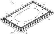
Fig. 2 is an isometric view of an additive manufacturing build unit with a vibration-isolation interface according to an example of principles described herein.
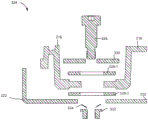
Fig. 3 is an exploded cross-sectional view of an additive manufacturing build unit with a vibration-isolation interface according to an example of principles described herein.
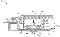
Fig. 4 is a cross-sectional view of an additive manufacturing build unit with a vibration-isolation interface according to an example of principles described herein.
Throughout the drawings, identical reference numbers designate similar, but not necessarily identical, elements. The drawings are not necessarily to scale and the dimensions of some of the elements may be exaggerated to more clearly illustrate the displayed examples. Moreover, the figures provide examples and/or embodiments consistent with the description; however, the description is not limited to the examples and/or implementations provided in the figures.
Detailed Description
An additive manufacturing device produces a three-dimensional (3D) object by solidifying a layer of build material on a bed within the device. The additive manufacturing apparatus makes the object based on data in the generated 3D model of the object, for example, using a Computer Aided Drafting (CAD) computer program product. The model data is processed into slices, each slice defining a portion of the layer of build material to be solidified.
In one example, to form a 3D object, build material, which may be a powder, is deposited on a bed. A fusing agent is then dispensed onto the to-be-fused portion of the layer of build material to form the 3D object layer. Systems that perform this type of additive manufacturing may be referred to as powder and molten agent based systems. The molten agent disposed in a desired pattern increases the energy absorption of the underlying layer of build material on which the agent is disposed. The build material is then exposed to energy, e.g., electromagnetic radiation. The electromagnetic radiation may include infrared light, laser light, or other suitable electromagnetic radiation. Due to the increased heat absorption properties imparted by the melting agent, those portions of the build material on which the melting agent is disposed are heated to a temperature greater than the melting temperature for the build material.
Thus, as energy is applied to the surface of the build material, the build material that has received the molten agent and thus has increased energy absorption characteristics melts, while the portion of the build material that does not receive the molten agent remains in powder form. Those portions of the build material that receive the agent and therefore have increased heat absorption properties may be referred to as melt portions. In contrast, the heat applied is not large enough to increase the heat of the portion of the build material without the agent to this melting temperature. Those portions of the build material that do not receive the agent and therefore do not have increased heat absorption properties may be referred to as unmelted portions.
Thus, a predetermined amount of heat is applied to the entire bed of build material, and due to the increased heat absorption properties imparted by the melting agent, the portion of the build material that receives the melting agent melts and forms an object, while in the presence of such application of thermal energy, the unmelted portion of the build material is unaffected, i.e., does not melt. This process is repeated in a layered fashion to generate the 3D object. The unmelted portions of the material may then be separated from the melted portions and the unmelted portions recycled for subsequent 3D printing operations. Although specific reference is made to one type of additive manufacturing process, the principles described herein may be applied to other types of additive manufacturing processes.
Accordingly, the present specification describes improved systems and methods for separating unmelted build material from molten build material. According to this system, the apparatus comprises an additive manufacturing build unit comprising a bed on which build material is deposited. The bed will vibrate so that after the 3D object is formed, the unmelted build material is 1) separated from the 3D object, and 2) directed to a port that returns the unmelted build material to the build material reservoir.
The building unit may also comprise non-vibrating components. For example, the frame holding the bed may include components such as bearings, screws, sensors, and other mechanical and electrical components, which if vibrated too much can damage those components and affect the overall performance of the additive manufacturing process. Furthermore, the building unit may also include components that are desired to remain dust-free. That is, during 3D printing with powder materials, dust is a common byproduct that can damage the operation of certain components.
Thus, the additive manufacturing build unit further comprises an interface between the vibrating bed body and the non-vibrating part of the build unit. The interface isolates the vibration to the vibrating bed so that these non-vibrating components do not vibrate as a result of the operation of the vibrating bed. More specifically, the interface 1) prevents horizontal movement of the vibrating bed relative to the non-vibrating frame during additive manufacturing, 2) allows movement of the vibrating bed relative to the non-vibrating component in a horizontal plane after additive manufacturing, and 3) prevents relative movement of the components in a vertical plane.
The construction unit further comprises a flexible seal deformable upon vibration of the vibrating bed body. The seal facilitates vibration of the vibrating bed while preventing powder from contaminating other areas within the additive manufacturing system. The flexible seal also centers the vibrating bed within the non-vibrating frame and helps prevent horizontal movement during 3D printing. In summary, a building unit may refer to a vibrating bed, a non-vibrating frame and/or a bed-frame interface and a flexible seal. In some examples, a build unit including a vibrating bed body and a non-vibrating frame may be removed from an additive manufacturing system (e.g., a 3D printer).
In particular, this specification describes an additive manufacturing build unit. The additive manufacturing build unit comprises a vibrating bed body on which a volume of build material is to be disposed. The bed will vibrate to remove excess build material. The construction unit further comprises a non-vibrating frame supporting the vibrating bed body. The bed-frame interface 1) couples the vibrating bed to the non-vibrating bed frame, and 2) isolates the vibration from the vibrating bed. The flexible seal combines a vibrating bed and a non-vibrating frame. The flexible seal 1) prevents build material from contaminating other areas of the additive manufacturing system, and 2) allows relative motion between the vibrating bed and the non-vibrating frame.
In another example, an additive manufacturing build unit includes a vibrating bed body and a non-vibrating frame. In this example, the bed-frame interface 1) couples the vibrating bed to the non-vibrating bed frame, 2) isolates the vibrations from the vibrating bed, 3) allows the vibrating bed to move in a horizontal plane when the vibration source is active, and 4) prevents the vibrating bed from moving in a vertical direction relative to the non-vibrating bed frame. The build unit further comprises a flexible seal that 1) prevents contamination of the build material, and 2) allows relative movement between the vibrating bed and the non-vibrating frame.
The present specification also describes an additive manufacturing system. An additive manufacturing system includes a build material dispenser to successively deposit layers of build material into a build area. At least one agent dispenser of the system includes at least one liquid injection device to selectively dispense a molten agent onto a layer of build material. The additive manufacturing system also includes a build unit on which the build material is to be disposed. The construction unit comprises a vibrating bed body, a non-vibrating frame, a bed body-frame interface and a flexible sealing element.
In summary, using such an additive manufacturing build unit 1) allows for an efficient additive manufacturing process by reusing unmelted build material, 2) increases the amount of unmelted build material that is recirculated via a vibratory build unit that directs unmelted build material to a port, 3) prevents contamination of the additive manufacturing system and prevents powder loss by containing build material within the build area, 4) improves the operational life of the build unit and associated additive manufacturing system by isolating vibrations to the vibrating bed, and 5) facilitates accurate object creation on the vibrating bed by preventing vertical vibrations and preventing horizontal vibrations during 3D printing. It is contemplated, however, that the devices disclosed herein may address other problems and deficiencies in several areas of technology.
As used in this specification and the appended claims, the term "build unit" refers to a platform on which build material is deposited during additive manufacturing, the build unit comprising a vibrating bed, a non-vibrating frame, a flexible seal, and a bed-frame interface.
Fig. 1 is a simplified top view of an additive manufacturing system (100) with a build cell (102) having a vibration-isolation interface, according to an example of principles described herein. In general, an apparatus for generating a three-dimensional object may be referred to as an additive manufacturing system (100). The system (100) described herein may correspond to a three-dimensional printing system, which may also be referred to as a three-dimensional printer. In an example of an additive manufacturing process, a layer of build material may be formed in a build region (104). As used in this specification and in the appended claims, the term "build region" refers to a region of space in which a 3D object is formed. The build region (104) may refer to a space bounded by the build cell (102) and the chamber walls.
Any number of functional agents may be deposited on the layer of build material during the additive manufacturing process. One such example is a fusing agent that helps harden the powder build material. In this particular example, the molten reagent may be selectively dispensed on the layer of build material in a pattern of three-dimensional object layers. The energy source may temporarily apply energy to the layer of build material. Energy may be selectively absorbed into patterned areas formed by the melting agent and blank areas without the melting agent, which causes the parts to selectively melt together. This process is then repeated until a complete solid object has been formed. Thus, as used herein, a build layer may refer to a layer of build material formed in a build region (104) upon which a functional agent may be dispensed and/or energy may be applied.
Additional layers may be formed and the operations described above may be performed for each layer to thereby generate a three-dimensional object. Sequentially layering and fusing portions of layers of build material on top of previous layers may facilitate the generation of a three-dimensional object. Layer-by-layer formation of a three-dimensional object may be referred to as a layered additive manufacturing process.
In examples described herein, the build material may comprise a powder-based build material, wherein the powder-based build material may comprise wet and/or dry powder-based material, particulate material, and/or granular material. In some examples, the build material may be a weakly light absorbing polymer. In some examples, the build material may be a thermoplastic. Further, as described herein, the functional agent may include a liquid that may aid in melting the build material when energy is applied. The fusing agent may be a light absorbing liquid, an infrared or near infrared absorbing liquid, for example, a pigment colorant.
An additive manufacturing system (100) includes a build material distributor (106) to successively deposit layers of build material in a build region (104). The build material dispenser (106) can include a wiper, a roller, and/or a spray mechanism. A build material dispenser (106) may be coupled to the scan carriage. In operation, a build material dispenser (106) places build material in a build area (104) as a scanning carriage moves along a scanning axis over the build area (104). Although fig. 1 depicts build material distributor (106) as being perpendicular to agent distributor (108), in some examples, build material distributor (106) may be in-line with agent distributor (108).
The additive manufacturing apparatus (100) comprises at least one agent distributor (108). The agent distributor (108) includes at least one liquid ejection device (110-1, 110-2) to distribute a functional agent onto the layer of build material.
One specific example of a functional agent is a fusing agent that increases the energy absorption of the portion of the build material that receives the fusing agent. The liquid ejection device (110) can include at least one printhead (e.g., a thermal ejection-based printhead, a piezoelectric ejection-based printhead, etc.). In some examples, an agent dispenser (106) is coupled to the scanning carriage, and the scanning carriage moves over the build area (104) along a scanning axis. In one example, a printhead used in an inkjet printing apparatus may be used as an agent dispenser (108). In this example, the molten agent may be a printing liquid. In other examples, the reagent dispenser (108) may include other types of liquid-ejection devices (110) that selectively eject small volumes of liquid.
The reagent dispenser (108) comprises at least one liquid ejection device (110), the liquid ejection device (110) having a plurality of liquid ejection dies arranged generally end-to-end along a width of the reagent dispenser (108). In such examples, the width of the agent distributor (108) corresponds to the size of the build area (104). The agent distributor (104) selectively distributes agent on build layers in the build area (104) while the scan carriage moves over the build area (104). In some example apparatus, the reagent dispenser (108) includes a nozzle (112-1, 112-2) through which molten reagent is selectively ejected (112-1, 112-2).
The additive manufacturing apparatus (100) also includes at least one heater (114) to selectively melt portions of the build material via application of heat to the build material to form the object. The heater (114) may be any component that applies thermal energy. Examples of heaters (114) include infrared lamps, visible halogen lamps, resistive heaters, Light Emitting Diodes (LEDs), and lasers. As described above, the build material may comprise meltable build material that melts together once the melting temperature is reached. Accordingly, the heater (114) may apply thermal energy to the build material, thereby heating portions of the build material above this melting temperature. Those portions that are heated above the melting temperature have molten agent disposed thereon and are formed in a pattern that will print the 3D object. The molten agent increases the absorptivity of the portion of the build material. Thus, the heater (114) may apply an amount of energy such that those portions with increased absorptivity reach temperatures greater than the melting temperature, while those portions without increased absorptivity do not reach temperatures greater than the melting temperature. Although specific reference is made to deposition of molten agents, the additive manufacturing apparatus (100) as described herein may apply any number of other functional agents.
A build unit (102) of an additive manufacturing system (100) includes components to isolate vibrations with respect to a bed portion on which build material is disposed. In particular, the build unit (102) includes a vibrating bed that holds a volume of build material. After the 3D object is formed, the vibration source causes the bed to vibrate to remove excess non-molten build material. The build unit (102) further comprises a non-vibrating frame. On the non-vibrating frame are mounted various components, for example, lifting devices that raise and lower the bed as successive layers of build material are added during the additive manufacturing process. That is, the build unit (102) may be moved in a vertical direction as successive layers of build material are deposited into the build area (104).
It is desirable to prevent vibrations caused by the vibration source from being transmitted to the frame and to ensure that the vibrating bed body is centered relative to the non-vibrating frame. Thus, the building unit (102) comprises an interface that couples the vibrating bed with other non-vibrating components and at the same time isolates the vibrations for the vibrating bed. A flexible seal between the vibrating bed body and the non-vibrating frame prevents build material from contaminating other components of the build unit (102) and centers the vibrating bed body relative to the non-vibrating frame. That is, the flexible seal holds the build material to the bed. The seal also allows relative movement between the vibrating bed and the non-vibrating bed.
Fig. 2 is an isometric view of an additive manufacturing build unit (102) with a vibration-isolation interface according to an example of principles described herein. In particular, fig. 2 depicts a vibrating bed body (216), the vibrating bed body (216) partially defining a build area (fig. 1, 104) in which additive manufacturing occurs.
During additive manufacturing, build material is placed on the vibrating bed (216), and the vibrating bed (216) does not vibrate. As successive layers form on the vibrating bed (216), the vibrating bed (216) travels downward. Once the entire 3D object is formed, it is removed from the build area (fig. 1, 104) and excess unmelted build material remains. This unmelted build material may be returned to the reservoir and used in subsequent operations. Thus, the bed (216) includes several ports (218) through which unmelted build material is drawn into the reservoir. For simplicity, a single port (218) is indicated with a reference numeral.
After the additive manufacturing process is completed, the vibrating bed (216) is activated such that it vibrates in a horizontal plane, as defined by arrows (219, 221). Such vibration moves build material around the bed (216) so that it is drawn into the port (218) to be transferred to the reservoir.
However, not all components of the building unit (102) are intended to vibrate. That is, the bed (216) may vibrate, but for other components, it may be desirable that it does not vibrate. For example, outside the vibrating bed (216), there may be other mechanical devices that may be damaged, such as bearings, screws, motors, and electrical connections. Thus, the present specification describes a build unit (102), the build unit (102)1) facilitating vibration of the bed (216) while preventing vibration of other components. Such a building unit (102) comprises an interface for allowing such relative movement, which interface is depicted in fig. 3 and 4.
The build unit (102) also includes a flexible seal (220). As described above, some components of the build cell (102) may benefit from the lack of vibration. Such components, among others, may also benefit from a lack of contamination by the build material. That is, during vibration to move unmelted build material toward port (218), powder material may lift off of bed (216) and move around over build unit (102). In addition, during printing, the effect of the molten agent on the build material may cause particulate matter to lift off the bed (216). Such particulate matter, regardless of how it is generated, can affect the performance of various components. The flexible seal prevents this contamination. That is, the flexible seal (220) allows relative movement of the vibrating bed (216) and the non-vibrating frame (222) while sealing components of the additive manufacturing system against contamination by build material particulate matter. For example, the flexible seal (220) may prevent particulate matter from becoming in contact with components below the build cell (102). As can be seen in fig. 2, in some examples, the flexible seal (222) is a closed form that surrounds the vibrating bed (216). In this case, a flexible seal (222) retains the build material within the build area (fig. 1, 104).
An additive manufacturing build unit (102) as described herein allows for easy separation of unmelted build material from melted build material that has been formed as part of a 3D object. The interface isolation described herein will be limited to any vibrations of the vibrating bed (216) and prevent these vibrations from reaching the non-vibrating frame (222).
Fig. 3 is an exploded view of an example vibration-isolation interface (324) according to principles described herein. As described above, the additive manufacturing build unit (fig. 1, 102) comprises a vibrating bed (216), which vibrating bed (216) vibrates after additive manufacturing to remove excess unmelted build material from the build area (fig. 1, 104) to a reservoir to be held for subsequent additive manufacturing operations. However, during additive manufacturing, the vibrating bed body (216) remains rigid such that the 3D object is accurately generated.
The additive manufacturing build unit (fig. 1, 102) also includes a non-vibrating frame (222). The non-vibrating frame (222) supports the vibrating bed (216) and other components obtained within the additive manufacturing system (fig. 1, 100). For example, during additive manufacturing, the vibrating bed (216) may be lowered so that additional layers of build material may be deposited and fused. The non-vibrating frame (222) may support a lifting mechanism that facilitates this raising and lowering. After additive manufacturing, the vibrating bed (216) vibrates to draw excess unmelted build material into the reservoir. If allowed to pass to the non-vibrating frame (222), the resulting vibrations may damage these other components, including the lifting mechanism, bearings and screws, as well as other electrical and mechanical components. Thus, the building unit (fig. 1, 102) comprises a bed-frame interface (324) to couple these components. Specifically, within the bed-frame interface (324), there are components that couple the vibrating bed (216) to the non-vibrating bed frame (222) and also isolate the vibration to the vibrating bed (216).
Specifically, the bed-frame interface (324) includes several movement limiting devices for 1) allowing the vibrating bed (216) to move in a horizontal plane after additive manufacturing, 2) preventing horizontal movement during printing when the vibration source is inactive, and 3) preventing the vibrating bed from moving in a vertical direction relative to the non-vibrating frame (222). The movement restriction device may be arranged around the edge of the vibrating bed (216). That is, the vibrating bed (216) may be surrounded by a flexible seal (fig. 2, 220) and a bed-frame interface (324), and a movement restriction device may be disposed in a corner of the bed-frame interface (324).
Returning to the motion restriction device. In some examples, these components operate to allow movement in certain directions and prevent movement in other directions. For example, the bed-frame interface (324) includes bolts (326) to pass through the vibrating bed (216) opening and the non-vibrating frame (222) opening. A first low friction bearing (328-1) is juxtaposed between the washer (330) and the vibrating bed (216). A second low friction bearing (328-2) is juxtaposed between the non-vibrating frame (222) and the vibrating bed (216).
Tightening a nut (332) on the bottom of the bolt (326) compresses the components together so that the adjacent surfaces are in contact with each other. In this case, the nut (332) and the bolt (326) are restricted from relative movement in the vertical direction (436). However, to ensure that the nut (332) is not over tightened so that components coupled to the bolt (326) will not move in a horizontal plane relative to each other, the spring (334) and in some cases the groove cut into the bolt (330) ensure that the nut (332) is not over tightened.
The compression of the components also ensures the rigidity of the vibrating bed (216) during manufacture. That is, there may be sufficient friction between the components such that the components do not move in a horizontal plane relative to each other when the vibration source is inactive during additive manufacturing. The friction force, which depends on the pressure applied by tightening the nut (332) against the spring (330), is such that it is overcome by the activation of the vibration source. That is, the force caused by the vibration source overcomes the frictional force and allows the vibrating bed (216) to vibrate.
This motion limiting device allows the vibrating bed (216) to move in a horizontal plane relative to the non-vibrating frame (222) while the vibration source is active, and prevents such relative motion in the vertical direction. Vertical motion can have a negative impact on 3D printed object quality. That is, if the vibrating bed (216) on which the 3D object is formed moves in a vertical direction relative to the non-vibrating frame (222), the thickness of the build material may change, which results in a lack of part accuracy, and/or other defects in the additive manufacturing process. Thus, since vertical motion may have a negative impact on 3D object accuracy, an interface that prevents this motion allows for more accurate 3D printing. Additional details regarding the operation of the motion restriction device are provided below with respect to fig. 4.
Fig. 4 is a cross-sectional view of a portion of an additive manufacturing build unit (102) having a vibration-isolation interface (324), according to an example of principles described herein. The vibrating bed (216) and the non-vibrating frame (222) are clearly depicted in fig. 4. As described above, the vibrating bed (216) is allowed to vibrate in the horizontal plane when the vibration source is active, but is prevented from vibrating in the horizontal plane when the vibration source is inactive. That is, during removal of unmelted build material, the vibrating bed (216) moves in the direction indicated by arrow (434) as well as the direction that is vertical but in the horizontal plane. A flexible seal (220) allows such movement. For example, the flexible seal (220) may be formed of a deformable silicon material and may have an S-shaped cross-section. Thus, as the vibrating bed (216) vibrates in the direction indicated by arrow (434), the flexible seal (220) deforms to allow movement, but still provides a sealing surface below the flexible seal (220). The flexible seal (220) also serves to center the vibrating bed (216) relative to the non-vibrating frame (222) and prevent horizontal movement during additive manufacturing (i.e., when the vibration source is inactive). As depicted in fig. 4, the flexible seal (220) is fixedly attached to both the vibrating bed (216) and the non-vibrating frame (222).
The flexible seal (220) also prevents contamination of the build material. That is, those components whose properties may be degraded by the presence of particulate build material may be shielded under the vibrating bed (216) and prevented from the ingress of build material therein by the flexible seal (220).
Figure 4 also clearly depicts the movement limiting means. As described above, the movement limiting device may be any device that allows movement in one plane (i.e., a horizontal plane) but prevents motion in a vertical direction (i.e., a vertical direction as indicated by arrow (436)). Allowing motion in the horizontal plane facilitates removal of unmelted build material, and preventing motion in the vertical direction enhances the efficiency of 3D object generation.
In one particular example, the movement limiting device includes a bolt (326), the bolt (326) passing through a washer (330), a first low friction bearing (328-1), an opening in the vibrating bed (216), a second low friction bearing (328-2), and an opening in the non-vibrating frame (222) from top to bottom. Fig. 4 also depicts a nut (332) on the bottom of the bolt (326), which nut (332) compresses these components together so that adjacent surfaces are in contact with each other. However, when the vibration source is active, movement is still permitted in the horizontal plane via the low friction bearing (328). Specifically, there is no relative motion between the vibrating bed (216) and the low friction bearing (328) even when the vibration source is active, due to the frictional forces between the low friction bearing (328) and the vibrating bed (216). I.e. they move together. However, the surfaces of the low friction bearing (328) that are in contact with the washer (330) and the non-vibrating frame (222), respectively, are formed of a low friction material, which allows the bearing (328) to slide along the corresponding surfaces of the washer (330) and the non-vibrating frame (222) when the vibration source is active. In some examples, the low friction bearing (328) may be formed from polytetrafluoroethylene, teflon-impregnated composites, or other teflon-based materials. The opening of each of these components is larger than the outer diameter of the bolt (326) so that it can slide about the axis of the bolt (326). Thus, the vibrating bed (216) and low friction bearing (328) vibrate, while the washer (330), bolt (326) and non-vibrating frame (222) do not vibrate.
In some examples, the movement limiting device includes a spring (334) to maintain a predetermined pressure on the contact surfaces of the bolt (326), washer (330), low friction bearing (328), vibrating bed (216), and non-vibrating frame (222). That is, if the nut (332) is over tightened, the friction between the surfaces (even those of the low friction bearing (328)) may be large enough to prevent horizontal movement even when the vibration source is active. That is, the spring (334) generates a predetermined pressure and facilitates a simple way of tightening the nut (332) to achieve this pressure.
The predetermined pressure may be such that there is no horizontal motion during additive manufacturing, but there is horizontal motion when the vibration source is operating after additive manufacturing. That is, during additive manufacturing, there is sufficient friction between these components and the flexible seal (220) has sufficient rigidity such that there is no movement in the horizontal plane. Then, after additive manufacturing, as the vibration source is activated to vibrate the bed (216), this friction and stiffness of the flexible seal (220) is overcome, causing the vibrating bed (216) to vibrate in a horizontal plane.
Still further, in some examples, the motion restriction device includes a cover (442) to prevent contamination of the motion restriction device by particulate build material that may degrade performance of the motion restriction device if access is allowed.
The motion limiting device as described herein allows the vibrating bed (216) to vibrate about the bolts (326), but also prevents differences in the vertical movement of the vibrating bed (216) relative to the non-vibrating frame (222). Preventing such relative vertical motion increases the efficiency of 3D object formation. Allowing the vibration of the vibrating bed (216) helps to effectively remove particulate matter after the 3D object is formed.
In summary, using such an additive manufacturing build unit 1) allows for an efficient additive manufacturing process by reusing unmelted build material, 2) increases the amount of unmelted build material that is recirculated through the vibratory build unit that directs unmelted build material to the port, 3) prevents contamination of the additive manufacturing system and prevents powder loss by containing build material within the build area, 4) improves the operational life of the build unit and associated additive manufacturing system by isolating vibrations to the vibrating bed, and 5) facilitates accurate object creation on the vibrating bed by preventing vertical vibrations. It is contemplated, however, that the devices disclosed herein may address other problems and deficiencies in several areas of technology.
The foregoing description has been presented to illustrate and describe examples of the principles described. This description is not intended to be exhaustive or to limit these principles to any precise form disclosed. Many modifications and variations are possible in light of the above teaching.
Claims (15)
1. An additive manufacturing build unit comprising:
vibrating a bed on which a volume of build material is to be placed, the bed being vibrated to remove excess build material;
a non-vibrating frame to support the vibrating bed body; and
a bed-frame interface for:
coupling the vibrating bed to the non-vibrating bed frame; and
isolating vibration to the vibrating bed body; and
a flexible seal between the vibrating bed and the non-vibrating frame for:
preventing build material from contaminating an additive manufacturing system in which the additive manufacturing build unit is disposed; and
allowing relative movement between the vibrating bed and the non-vibrating frame.
2. Additive manufacturing build unit according to claim 1, wherein the bed-frame interface comprises a number of movement limiting means for:
when the vibration source moves, the vibration bed body is allowed to move in a horizontal plane;
when the vibration source is inactive, the vibration bed body is prevented from moving in a horizontal plane; and
the vibration bed body is prevented from moving in the vertical direction relative to the non-vibration frame.
3. An additive manufacturing build unit according to claim 2, wherein each movement limiting device comprises:
the bolt penetrates through the opening of the vibrating bed body and the opening of the non-vibrating frame;
a nut to engage with the bolt to apply a predetermined pressure on the vibrating bed and non-vibrating frame joint;
the first low-friction bearing is juxtaposed between the non-vibrating frame and the vibrating bed body; and
and the second low-friction bearing is juxtaposed between the vibrating bed body and the washer.
4. An additive manufacturing build unit according to claim 3 wherein the bolt comprises a groove to prevent over-tightening of the nut.
5. The additive manufacturing build unit of claim 3, wherein each movement limiting device further comprises a spring disposed between the nut and the non-vibrating frame to adjust the predetermined pressure.
6. The additive manufacturing build unit of claim 3, wherein the low friction bearing is formed from a polytetrafluoroethylene compound.
7. The additive manufacturing build unit of claim 1, wherein the flexible seal has an S-shaped cross-section.
8. The additive manufacturing build unit of claim 1, wherein the flexible seal is formed from a deformable silicone material, rubber, or a fluoroelastomer material.
9. An additive manufacturing build unit comprising:
vibrating a bed on which a volume of build material is to be disposed, the bed being vibrated to remove excess non-molten build material;
a non-vibrating frame to support the vibrating bed body; and
a bed-frame interface for:
coupling the vibrating bed to the non-vibrating bed frame; and
isolating vibration to the vibrating bed body;
when the vibration source moves, the vibration bed body is allowed to move in a horizontal plane;
when the vibration source is inactive, the vibration bed body is prevented from moving in a horizontal plane; and
the vibration bed body is prevented from moving in the vertical direction; and
a flexible seal between the vibrating bed and the non-vibrating frame for:
preventing contamination of build material; and
allowing relative movement between the vibrating bed and the non-vibrating frame.
10. The additive manufacturing build unit of claim 9, wherein the flexible seal:
is in a closed form surrounding the vibrating bed body; and
centering the vibrating bed body within the non-vibrating frame.
11. An additive manufacturing build unit according to claim 9, wherein the bed-frame interface comprises a number of movement limiting devices arranged in corners of the bed-frame interface.
12. The additive manufacturing build unit of claim 11, wherein each movement limiting device further comprises a cover to prevent contamination of the movement limiting device.
13. An additive manufacturing system, comprising:
a build material distributor to successively deposit layers of build material into a build area;
at least one agent dispenser comprising at least one liquid jet device to selectively dispense a molten agent onto the layer of build material; and
a build unit defining a build area, wherein the build unit comprises:
vibrating a bed on which a volume of build material is to be disposed, the bed vibrating to remove excess build material;
a non-vibrating frame to support the vibrating bed body; and
a bed-frame interface for:
coupling the vibrating bed to the non-vibrating bed frame; and
isolating vibration to the vibrating bed body; and
a flexible seal between the vibrating bed and the non-vibrating frame for:
preventing contamination of build material; and
allowing relative movement between the vibrating bed and the non-vibrating frame.
14. The additive manufacturing system of claim 13, wherein the build unit moves in a vertical direction as successive layers of build material are deposited into the build area.
15. The additive manufacturing system of claim 13, wherein the flexible seal has a cross-section that allows relative motion at low forces.
Applications Claiming Priority (1)
| Application Number | Priority Date | Filing Date | Title |
|---|---|---|---|
| PCT/US2017/040929 WO2019009905A1 (en) | 2017-07-06 | 2017-07-06 | Additive manufacturing with vibration-isolating interface |
Publications (1)
| Publication Number | Publication Date |
|---|---|
| CN110891762A true CN110891762A (en) | 2020-03-17 |
Family
ID=64950309
Family Applications (1)
| Application Number | Title | Priority Date | Filing Date |
|---|---|---|---|
| CN201780092830.3A Pending CN110891762A (en) | 2017-07-06 | 2017-07-06 | Additive manufacturing with vibration isolation interface |
Country Status (4)
| Country | Link |
|---|---|
| US (1) | US11230060B2 (en) |
| EP (1) | EP3648951A4 (en) |
| CN (1) | CN110891762A (en) |
| WO (1) | WO2019009905A1 (en) |
Families Citing this family (2)
| Publication number | Priority date | Publication date | Assignee | Title |
|---|---|---|---|---|
| DE102021201170A1 (en) | 2021-02-09 | 2022-08-11 | MTU Aero Engines AG | Method for avoiding resonance damage during cleaning of an at least partially additively manufactured component, and cleaning device |
| WO2023048749A1 (en) * | 2021-09-21 | 2023-03-30 | Hewlett-Packard Development Company, L.P. | Incremental build material spread |
Citations (8)
| Publication number | Priority date | Publication date | Assignee | Title |
|---|---|---|---|---|
| US5693144A (en) * | 1990-03-19 | 1997-12-02 | 3D Systems, Inc. | Vibrationally enhanced stereolithographic recoating |
| EP1759791A1 (en) * | 2005-09-05 | 2007-03-07 | Nederlandse Organisatie voor toegepast- natuurwetenschappelijk onderzoek TNO | Apparatus and method for building a three-dimensional article |
| US7285237B2 (en) * | 2001-10-03 | 2007-10-23 | 3D Systems, Inc. | Post processing three-dimensional objects formed by selective deposition modeling |
| CN101326046A (en) * | 2005-09-20 | 2008-12-17 | Pts软件公司 | An apparatus for building a three-dimensional article and a method for building a three-dimensional article |
| CN203719863U (en) * | 2013-12-16 | 2014-07-16 | 广西大学 | Multifunctional vibration test platform |
| TW201632344A (en) * | 2014-10-01 | 2016-09-16 | 松下知識產權經營股份有限公司 | Method for producing three-dimensional shaped object |
| CN106424730A (en) * | 2016-10-25 | 2017-02-22 | 华南理工大学 | Centrifugal supplying and vibrating compaction device and method for powder for 3D printing |
| CN106424728A (en) * | 2016-10-17 | 2017-02-22 | 重庆大学 | Powder-recyclable selective laser melting equipment and processing method thereof |
Family Cites Families (14)
| Publication number | Priority date | Publication date | Assignee | Title |
|---|---|---|---|---|
| US3427034A (en) * | 1964-09-21 | 1969-02-11 | Robbins Aviat Inc | Dynamic shaft seal |
| US3528144A (en) * | 1966-07-12 | 1970-09-15 | Edward L Haponski | Concrete casting table |
| EP1663461A4 (en) | 2003-07-30 | 2009-01-14 | Phase Inc | Filtration system with enhanced cleaning and dynamic fluid separation |
| US7497443B1 (en) | 2005-05-03 | 2009-03-03 | The United States Of America As Represented By The Administrator Of The National Aeronautics And Space Administration | Resilient flexible pressure-activated seal |
| US20080047628A1 (en) | 2006-05-26 | 2008-02-28 | Z Corporation | Apparatus and methods for handling materials in a 3-D printer |
| US8888480B2 (en) | 2012-09-05 | 2014-11-18 | Aprecia Pharmaceuticals Company | Three-dimensional printing system and equipment assembly |
| EP3096906A4 (en) | 2014-01-22 | 2017-03-08 | United Technologies Corporation | Additive manufacturing system and method of operation |
| US10377061B2 (en) | 2014-03-20 | 2019-08-13 | Shapeways, Inc. | Processing of three dimensional printed parts |
| US10016852B2 (en) | 2014-11-13 | 2018-07-10 | The Boeing Company | Apparatuses and methods for additive manufacturing |
| US10315408B2 (en) * | 2015-04-28 | 2019-06-11 | General Electric Company | Additive manufacturing apparatus and method |
| FR3039437B1 (en) * | 2015-07-30 | 2021-12-24 | Michelin & Cie | PROCESS FOR DRY CLEANING OF ADDITIVE MANUFACTURING TRAYS |
| US10913206B2 (en) | 2015-08-03 | 2021-02-09 | Delavan, Inc | Systems and methods for post additive manufacturing processing |
| CN113561478B (en) | 2015-10-30 | 2023-06-06 | 速尔特技术有限公司 | Additive manufacturing system and method |
| EP3167980A1 (en) | 2015-11-13 | 2017-05-17 | SLM Solutions Group AG | Unpacking device allowing residual raw material powder removal |
-
2017
- 2017-07-06 WO PCT/US2017/040929 patent/WO2019009905A1/en unknown
- 2017-07-06 US US16/075,681 patent/US11230060B2/en active Active
- 2017-07-06 EP EP17917032.9A patent/EP3648951A4/en not_active Withdrawn
- 2017-07-06 CN CN201780092830.3A patent/CN110891762A/en active Pending
Patent Citations (8)
| Publication number | Priority date | Publication date | Assignee | Title |
|---|---|---|---|---|
| US5693144A (en) * | 1990-03-19 | 1997-12-02 | 3D Systems, Inc. | Vibrationally enhanced stereolithographic recoating |
| US7285237B2 (en) * | 2001-10-03 | 2007-10-23 | 3D Systems, Inc. | Post processing three-dimensional objects formed by selective deposition modeling |
| EP1759791A1 (en) * | 2005-09-05 | 2007-03-07 | Nederlandse Organisatie voor toegepast- natuurwetenschappelijk onderzoek TNO | Apparatus and method for building a three-dimensional article |
| CN101326046A (en) * | 2005-09-20 | 2008-12-17 | Pts软件公司 | An apparatus for building a three-dimensional article and a method for building a three-dimensional article |
| CN203719863U (en) * | 2013-12-16 | 2014-07-16 | 广西大学 | Multifunctional vibration test platform |
| TW201632344A (en) * | 2014-10-01 | 2016-09-16 | 松下知識產權經營股份有限公司 | Method for producing three-dimensional shaped object |
| CN106424728A (en) * | 2016-10-17 | 2017-02-22 | 重庆大学 | Powder-recyclable selective laser melting equipment and processing method thereof |
| CN106424730A (en) * | 2016-10-25 | 2017-02-22 | 华南理工大学 | Centrifugal supplying and vibrating compaction device and method for powder for 3D printing |
Also Published As
| Publication number | Publication date |
|---|---|
| US11230060B2 (en) | 2022-01-25 |
| EP3648951A4 (en) | 2021-02-24 |
| US20210197475A1 (en) | 2021-07-01 |
| EP3648951A1 (en) | 2020-05-13 |
| WO2019009905A1 (en) | 2019-01-10 |
Similar Documents
| Publication | Publication Date | Title |
|---|---|---|
| RU2417890C2 (en) | Device to producing 3d article and method of producing said article | |
| US10919214B2 (en) | Method and apparatus for manufacturing structure | |
| JP6846433B2 (en) | 3D printing system | |
| WO2017088796A1 (en) | High-speed reciprocating color 3d printer | |
| JP2021107150A (en) | Three-dimensional modeling method and device for objects with high resolution background | |
| CN106671403B (en) | System and method for removing a support structure from a three-dimensional printed object using microwave energy and nanoparticles | |
| EP3230048A1 (en) | Generating three-dimensional objects | |
| US11273594B2 (en) | Modifying data representing three-dimensional objects | |
| WO2016080993A1 (en) | Generating three-dimensional objects | |
| TW201536534A (en) | Generating a three-dimensional objects | |
| KR102182440B1 (en) | System for detecting inoperative inkjets in three-dimensional object printing using an optical sensor and reversible thermal substrates | |
| EP3433080B1 (en) | Additive manufacturing transport devices | |
| CN110891762A (en) | Additive manufacturing with vibration isolation interface | |
| US11518102B2 (en) | Build material extraction using vibration and airflow | |
| EP3632655A1 (en) | 3d printing machine and method | |
| JPH08294742A (en) | Method and device for making prototype containing part and support | |
| JP6883658B2 (en) | Integration of 3D printing processing | |
| KR20230062477A (en) | Additive manufacturing methods within an adjustable confinement medium | |
| US20220371271A1 (en) | 3d printing modules with build platform driving mechanisms | |
| EP3539774B1 (en) | Three-dimensional fabricating apparatus and three-dimensional fabricating method | |
| WO2016053364A1 (en) | Generating three-dimensional objects and generating images on substrates | |
| JP6705230B2 (en) | Device for ejecting liquid | |
| EP3094476B1 (en) | Generating three-dimensional objects | |
| WO2019147218A1 (en) | Carriage assembly for an additive manufacturing system | |
| CN220700401U (en) | Photo-curing type three-dimensional printing equipment and printing system |
Legal Events
| Date | Code | Title | Description |
|---|---|---|---|
| PB01 | Publication | ||
| PB01 | Publication | ||
| SE01 | Entry into force of request for substantive examination | ||
| SE01 | Entry into force of request for substantive examination | ||
| WD01 | Invention patent application deemed withdrawn after publication |
Application publication date: 20200317 |
|
| WD01 | Invention patent application deemed withdrawn after publication |