CN110886540B - Security fence with folding and stretching functions - Google Patents
Security fence with folding and stretching functions Download PDFInfo
- Publication number
- CN110886540B CN110886540B CN201911258091.8A CN201911258091A CN110886540B CN 110886540 B CN110886540 B CN 110886540B CN 201911258091 A CN201911258091 A CN 201911258091A CN 110886540 B CN110886540 B CN 110886540B
- Authority
- CN
- China
- Prior art keywords
- plate
- sleeve
- groove
- spring
- folding
- Prior art date
- Legal status (The legal status is an assumption and is not a legal conclusion. Google has not performed a legal analysis and makes no representation as to the accuracy of the status listed.)
- Active
Links
- 239000004744 fabric Substances 0.000 claims abstract description 7
- XEEYBQQBJWHFJM-UHFFFAOYSA-N Iron Chemical compound [Fe] XEEYBQQBJWHFJM-UHFFFAOYSA-N 0.000 claims description 20
- 238000004804 winding Methods 0.000 claims description 13
- 229910052742 iron Inorganic materials 0.000 claims description 10
- 238000003466 welding Methods 0.000 claims description 6
- 230000000694 effects Effects 0.000 claims description 5
- 238000009434 installation Methods 0.000 claims description 4
- 238000010276 construction Methods 0.000 description 11
- 230000008878 coupling Effects 0.000 description 3
- 238000010168 coupling process Methods 0.000 description 3
- 238000005859 coupling reaction Methods 0.000 description 3
- 230000003139 buffering effect Effects 0.000 description 2
- 238000000034 method Methods 0.000 description 2
- 230000008569 process Effects 0.000 description 2
- 230000009286 beneficial effect Effects 0.000 description 1
- 238000010586 diagram Methods 0.000 description 1
- 238000005516 engineering process Methods 0.000 description 1
- 230000006872 improvement Effects 0.000 description 1
- 238000010030 laminating Methods 0.000 description 1
- 230000004048 modification Effects 0.000 description 1
- 238000012986 modification Methods 0.000 description 1
Images


Classifications
-
- E—FIXED CONSTRUCTIONS
- E04—BUILDING
- E04H—BUILDINGS OR LIKE STRUCTURES FOR PARTICULAR PURPOSES; SWIMMING OR SPLASH BATHS OR POOLS; MASTS; FENCING; TENTS OR CANOPIES, IN GENERAL
- E04H17/00—Fencing, e.g. fences, enclosures, corrals
- E04H17/14—Fences constructed of rigid elements, e.g. with additional wire fillings or with posts
-
- E—FIXED CONSTRUCTIONS
- E01—CONSTRUCTION OF ROADS, RAILWAYS, OR BRIDGES
- E01F—ADDITIONAL WORK, SUCH AS EQUIPPING ROADS OR THE CONSTRUCTION OF PLATFORMS, HELICOPTER LANDING STAGES, SIGNS, SNOW FENCES, OR THE LIKE
- E01F9/00—Arrangement of road signs or traffic signals; Arrangements for enforcing caution
- E01F9/60—Upright bodies, e.g. marker posts or bollards; Supports for road signs
- E01F9/604—Upright bodies, e.g. marker posts or bollards; Supports for road signs specially adapted for particular signalling purposes, e.g. for indicating curves, road works or pedestrian crossings
- E01F9/619—Upright bodies, e.g. marker posts or bollards; Supports for road signs specially adapted for particular signalling purposes, e.g. for indicating curves, road works or pedestrian crossings with reflectors; with means for keeping reflectors clean
-
- E—FIXED CONSTRUCTIONS
- E01—CONSTRUCTION OF ROADS, RAILWAYS, OR BRIDGES
- E01F—ADDITIONAL WORK, SUCH AS EQUIPPING ROADS OR THE CONSTRUCTION OF PLATFORMS, HELICOPTER LANDING STAGES, SIGNS, SNOW FENCES, OR THE LIKE
- E01F9/00—Arrangement of road signs or traffic signals; Arrangements for enforcing caution
- E01F9/60—Upright bodies, e.g. marker posts or bollards; Supports for road signs
- E01F9/658—Upright bodies, e.g. marker posts or bollards; Supports for road signs characterised by means for fixing
- E01F9/669—Upright bodies, e.g. marker posts or bollards; Supports for road signs characterised by means for fixing for fastening to safety barriers or the like
Landscapes
- Engineering & Computer Science (AREA)
- Architecture (AREA)
- Civil Engineering (AREA)
- Structural Engineering (AREA)
- Refuge Islands, Traffic Blockers, Or Guard Fence (AREA)
Abstract
The invention discloses a safety fence with folding and stretching functions, wherein a shielding assembly is arranged at the top end of a connecting rod, positioning screws are respectively arranged at the top end of a first sleeve and the bottom end of a second sleeve, a lower baffle is arranged on the top surface of a first connecting plate, an upper baffle is arranged on the bottom surface of a second connecting plate, a positioning assembly is welded at the bottom end of the connecting rod, a connecting ball is welded at the bottom end of an adjusting screw, a limiting rod penetrates through a limiting hole, plastic cloth is bonded at the edge between the adjusting plate and a counterweight plate, and a connecting assembly is arranged at the bottom end of the side surface of the first sleeve and the top end of the second sleeve. The bottom surface of the counterweight plate is attached to the ground, and the rail is stably placed.
Description
Technical Field
The invention relates to the technical field of fences, in particular to a safety fence with a folding and stretching function.
Background
Hydraulic and hydroelectric engineering can use security fence to enclose the fender to the job site in the work progress, keeps apart the construction area with not construction area, prevents that irrelevant personnel from missing and arousing the incident, improves the security, guarantees the normal clear of construction, plays safety warning's effect.
The patent with the publication number of CN208251810U mentions "a security fence for hydraulic and hydroelectric engineering", and this patent can stretch out and draw back folding, and the volume after folding is very little, is convenient for transport and transportation, can also be according to construction length, adjusts the length of security fence, but this fence needs the folded sheet cooperation to shelter from in the use, and the installation is inconvenient, and folding adjustable scope is less, and it is inconvenient to use.
Disclosure of Invention
The invention provides a safety fence with a folding and stretching function, which can effectively solve the problems that the fence provided by the background technology needs a folding plate to be matched with a shielding plate in the using process, the installation is inconvenient, the folding adjustable range is small, and the use is inconvenient.
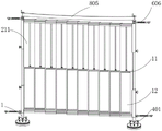
In order to achieve the purpose, the invention provides the following technical scheme: a safety fence with a folding and stretching function comprises a connecting rod, wherein a shielding assembly is arranged at the top end of the connecting rod and comprises a first sleeve, a movable rod, a second sleeve, a positioning screw rod, a first connecting plate, a second connecting plate, a T-shaped sliding groove, a T-shaped sliding block, a lower baffle, a T-shaped limiting block, an upper baffle and a guide opening;
the first sleeve is welded at the top end of the connecting rod, the first sleeve is movably sleeved at the bottom end of the movable rod, the top end of the movable rod is sleeved with a second sleeve, positioning screw rods are respectively installed at the top end of the first sleeve and the bottom end of the second sleeve, first connecting plates are uniformly distributed between the two first sleeves, the two first connecting plates are respectively welded at the bottom end of the side surface of the first sleeve, second connecting plates are uniformly distributed between the two second sleeves, the two second connecting plates are respectively welded at the top end of the side surface of the second sleeve, T-shaped chutes are respectively arranged at the front sides of the first connecting plate and the second connecting plate, T-shaped sliding blocks are respectively welded at the positions corresponding to the adjacent T-shaped chutes at one end of the back sides of the first connecting plate and the second connecting plate, a lower baffle is installed at the top surface of the first connecting plate, an upper baffle is installed on the bottom surface of the second connecting plate, and a guide opening is formed in the middle of the front surface of the upper baffle corresponding to the T-shaped limiting block.
Preferably, the front face of the top end of the lower baffle plate and the back face of the bottom end of the upper baffle plate are mutually attached.
Preferably, balls are uniformly embedded in the middle of the front face of the T-shaped limiting block.
Preferably, the bottom end of the connecting rod is welded with a positioning assembly, and the positioning assembly comprises a mounting plate, an adjusting screw, a connecting ball, an adjusting plate, a spherical groove, a limiting hole, a limiting rod, a first spring, a counterweight plate and plastic cloth;
the mounting panel welds in the connecting rod bottom, adjusting screw is installed through the screw thread in mounting panel top surface edge, the welding of adjusting screw bottom has the connection ball, connection ball bottom swing joint has the adjusting plate, the adjusting plate top surface corresponds and connects ball department and has seted up spherical groove, spacing hole has been seted up to adjusting plate top surface edge equidistance, spacing downthehole portion runs through there is the gag lever post, first spring has been cup jointed to the gag lever post bottom, first spring both ends weld respectively in adjusting plate bottom surface and counter weight top surface, the edge between adjusting plate and the counter weight bonds and has the plastic sheeting.
Preferably, the number of the adjusting screws is four, and the distances between the adjacent adjusting screws are the same.
Preferably, the welding of gag lever post top has the spacing piece, spacing piece diameter is the twice of gag lever post diameter, the gag lever post welds in counter weight plate top surface.
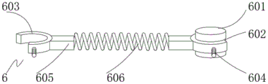
Preferably, the bottom end of the side surface of the first sleeve and the top end of the second sleeve are provided with connecting components, and each connecting component comprises a connecting block, a connecting groove, a C-shaped spring clamp, a positioning screw, a convex block and a second spring;
two the connecting block welds respectively in first sleeve pipe side bottom and second sleeve pipe top, the spread groove has been seted up at the connecting block middle part, spread groove internal connection has C type spring card, the positive mid-mounting of C type spring card has set screw, the welding of C type spring card side middle part has the lug, two the lug welds respectively in second spring both ends.
Preferably, a positioning groove is formed in the connecting groove corresponding to the positioning screw, and the width of the positioning groove is the same as that of the connecting groove.
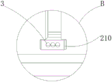
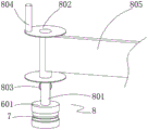
Preferably, a warning assembly is mounted at the top end of the connecting block at the top end of the second sleeve, and comprises a connecting shaft, a winding drum, a spring piece, a rotating handle and a reflective belt;
the connecting axle welds in the connecting block top surface middle part on second sleeve pipe top, connecting axle middle part activity cup joints around the reel, connecting axle bottom both sides correspond all to weld around reel bottom department has the spring leaf, the reflection of light area both ends bond respectively in two around reel side middle parts, it has the rotation handle to weld around reel top one side.
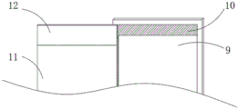
Preferably, the baffle openly middle part has seted up the sign groove down, the inside top in sign groove and bottom have all been bonded the iron sheet, the iron sheet openly laminates magnetic stripe, two the magnetic stripe bonds respectively in the sign board both ends.
Compared with the prior art, the invention has the beneficial effects that: the invention has scientific and reasonable structure and safe and convenient use:
1. be provided with and shelter from the subassembly, can pull first connecting plate and second connecting plate, the length of adjustment rail removes the second sleeve along the movable rod, the height of adjustable rail, and the control range is great, and the rail middle part shelters from through baffle and last baffle down, shelters from effectually, need not to dismantle and install, rail simple to operate.
2. Be provided with locating component, when ramp department construction, because of ground and horizontal plane nonparallel, a plurality of adjusting screw rods are rotated to the accessible, promote adjusting plate and weight plate slope, make weight plate bottom surface and ground laminating, and first spring can provide the buffering, and it is more stable when putting in the ramp to make the rail, prevents that the rail from empting, the safe construction.
3. Be provided with coupling assembling, link together a plurality of fences through coupling assembling, and C type spring card can be in the spread groove internal rotation, and the angle modulation between two fences is convenient, and when the fence of connecting received the striking, the second spring extension absorbed the impact, alleviateed the damage of fence.
4. Be provided with the warning subassembly, remind the vehicle of passing when being convenient for use night, and the warning subassembly can be accomodate along with the folding of rail, accomodate the convenience.
5. Corresponding sign board is put into in the sign groove, reminds passerby this regional construction type and danger, reminds the pedestrian to keep away from dodging, and the sign board adsorbs the iron sheet through the magnetic stripe and fixes, conveniently replaces.
Drawings
The accompanying drawings, which are included to provide a further understanding of the invention and are incorporated in and constitute a part of this specification, illustrate embodiments of the invention and together with the description serve to explain the principles of the invention and not to limit the invention.
In the drawings:
FIG. 1 is a schematic structural view of the present invention;
FIG. 2 is a schematic view of the shielding assembly of the present invention;
FIG. 3 is a schematic structural view of region A of the present invention;
FIG. 4 is a schematic structural view of the region B of the present invention;
FIG. 5 is a schematic structural view of the positioning assembly of the present invention;
FIG. 6 is a schematic structural view of the coupling assembly of the present invention;
FIG. 7 is a schematic structural diagram of a warning assembly of the present invention;
FIG. 8 is a schematic view of the installation structure of the iron sheet of the present invention;
reference numbers in the figures: 1. a connecting rod;
2. a shielding component; 201. a first sleeve; 202. a movable rod; 203. a second sleeve; 204. positioning a screw rod; 205. a first connecting plate; 206. a second connecting plate; 207. a T-shaped chute; 208. a T-shaped slider; 209. a lower baffle plate; 210. a T-shaped limiting block; 211. an upper baffle plate; 212. a guide port;
3. a ball bearing;
4. a positioning assembly; 401. mounting a plate; 402. adjusting the screw rod; 403. a connecting ball; 404. an adjustment plate; 405. a spherical groove; 406. a limiting hole; 407. a limiting rod; 408. a first spring; 409. a weight plate; 410. plastic cloth;
5. a limiting sheet;
6. a connecting assembly; 601. connecting blocks; 602. connecting grooves; 603. c-shaped spring clips; 604. a set screw; 605. a bump; 606. a second spring;
7. positioning a groove;
8. a warning component; 801. a connecting shaft; 802. winding the reel; 803. a spring plate; 804. rotating the handle; 805. a reflective band;
9. marking a slot; 10. iron sheets; 11. a magnetic strip; 12. and (4) marking the board.
Detailed Description
The preferred embodiments of the present invention will be described in conjunction with the accompanying drawings, and it will be understood that they are described herein for the purpose of illustration and explanation and not limitation.
Example (b): as shown in fig. 1 to 8, the invention provides a technical solution, and a safety fence with a folding telescopic function comprises a connecting rod 1, wherein a shielding component 2 is arranged at the top end of the connecting rod 1, and the shielding component 2 comprises a first sleeve 201, a movable rod 202, a second sleeve 203, a positioning screw 204, a first connecting plate 205, a second connecting plate 206, a T-shaped chute 207, a T-shaped slider 208, a lower baffle 209, a T-shaped limiting block 210, an upper baffle 211 and a guide opening 212;
the first sleeve 201 is welded at the top end of the connecting rod 1, the first sleeve 201 is movably sleeved at the bottom end of the movable rod 202, the top end of the movable rod 202 is sleeved with the second sleeve 203, the top end of the first sleeve 201 and the bottom end of the second sleeve 203 are both provided with positioning screws 204, first connecting plates 205 are uniformly distributed between the two first sleeves 201, the two first connecting plates 205 are respectively welded at the bottom ends of the side surfaces of the first sleeve 201, second connecting plates 206 are uniformly distributed between the two second sleeves 203, the two second connecting plates 206 are respectively welded at the top ends of the side surfaces of the second sleeve 203, the front surfaces of the first connecting plates 205 and the second connecting plates 206 are both provided with T-shaped chutes 207, T-shaped sliding blocks 208 are respectively welded at the positions corresponding to the adjacent T-shaped chutes 207 at one ends of the back surfaces of the first connecting plates 205 and the second connecting plates 206, the top surface of the, the inside top of sign groove 9 and the bottom all bond has iron sheet 10, iron sheet 10 openly has laminated magnetic stripe 11, two magnetic stripe 11 bond respectively in sign board 12 both ends, the passerby of being convenient for distinguishes the kind of construction, remind to dodge, there is T type stopper 210 baffle 209 front top down through the screw mounting, T type stopper 210 front middle part is evenly inlayed and is had ball 3, baffle 209 back is openly removed along T type stopper 210 when being convenient for fold down, overhead gage 211 is installed to second connecting plate 206 bottom surface, baffle 209 top is openly and is laminated each other with overhead gage 211 bottom back down, when baffle 209 is removed along overhead gage 211 down being convenient for, the space can not appear between lower baffle 209 and the overhead gage 211, overhead gage 211 openly middle part corresponds T type stopper 210 department and has seted up guide mouth 212.
The bottom end of the connecting rod 1 is welded with a positioning component 4, and the positioning component 4 comprises a mounting plate 401, an adjusting screw 402, a connecting ball 403, an adjusting plate 404, a spherical groove 405, a limiting hole 406, a limiting rod 407, a first spring 408, a counterweight plate 409 and plastic cloth 410;
the mounting plate 401 is welded at the bottom end of the connecting rod 1, the edge of the top surface of the mounting plate 401 is provided with the adjusting screws 402 by threads, the bottom end of the adjusting screws 402 is welded with the connecting ball 403, the bottom end of the connecting ball 403 is movably connected with an adjusting plate 404, the number of the adjusting screws 402 is four, the distance between the adjacent adjusting screws 402 is the same, the adjusting plate 404 is pushed by rotating different adjusting screws 402, so that the adjusting plate 404 reaches a proper inclination, the top surface of the adjusting plate 404 is provided with a spherical groove 405 corresponding to the connecting ball 403, the edge of the top surface of the adjusting plate 404 is provided with spacing holes 406 at equal intervals, a spacing rod 407 penetrates through the spacing holes 406, the bottom end of the spacing rod 407 is sleeved with a first spring 408, two ends of the first spring 408 are respectively welded at the bottom surface of the adjusting plate 404 and the top surface of the counterweight plate 409, the top end of the, the limiting rod 407 is prevented from being separated from the adjusting plate 404, the distance between the weight plate 409 and the adjusting plate 404 is limited, and the plastic cloth 410 is bonded at the edge between the adjusting plate 404 and the weight plate 409.
The connecting assembly 6 is mounted at the bottom end of the side surface of the first sleeve 201 and the top end of the second sleeve 203, and the connecting assembly 6 comprises a connecting block 601, a connecting groove 602, a C-shaped spring clamp 603, a positioning screw 604, a bump 605 and a second spring 606;
two connecting blocks 601 weld respectively in first sleeve 201 side bottom and second sleeve 203 top, connecting groove 602 has been seted up at connecting block 601 middle part, connecting groove 602 internal connection has C type spring card 603, C type spring card 603 openly mid-mounting has set screw 604, connecting groove 602 is inside to correspond set screw 604 department and has seted up constant head tank 7, constant head tank 7 width is the same with connecting groove 602 width in the set screw 604 one end embedding constant head tank 7 of being convenient for, fixed C type spring card 603, the welding of C type spring card 603 side middle part has lug 605, two lugs 605 weld respectively in second spring 606 both ends.
The top end of a connecting block 601 at the top end of the second sleeve 203 is provided with a warning assembly 8, and the warning assembly 8 comprises a connecting shaft 801, a winding drum 802, a spring piece 803, a rotating handle 804 and a reflective belt 805;
the connecting shaft 801 is welded to the middle of the top surface of the connecting block 601 at the top end of the second sleeve 203, the winding drums 802 are movably sleeved in the middle of the connecting shaft 801, spring pieces 803 are welded to two sides of the bottom end of the connecting shaft 801 corresponding to the bottom ends of the winding drums 802, two ends of the reflective tape 805 are respectively adhered to the middle of the side surfaces of the two winding drums 802, and the rotating handle 804 is welded to one side of the top end of the winding drum.
The working principle and the using process of the invention are as follows: two first sleeves 201 are pulled to two sides, a T-shaped sliding block 208 slides in a T-shaped sliding groove 207, balls 3 roll along the back of a lower baffle 209, an adjacent first connecting plate 205 and an adjacent second connecting plate 206 are gradually far away, the distance between the two first sleeves 201 is increased, the length of the fence is increased, the first sleeves 201 are pulled upwards, at the moment, the first sleeves 201 and a movable rod 202 are simultaneously stretched upwards, the back of an upper baffle 211 contacts the lower baffle 209 to slide in the front direction, a T-shaped limiting block 210 moves along a guide opening 212, the height of the fence is increased, the adjustment range is larger, the middle part of the fence is shielded through the lower baffle 209 and the upper baffle 211, the shielding effect is good, the fence does not need to be disassembled or assembled, and the fence is convenient to install;
if the plurality of adjusting screws 402 are rotated when the slope is constructed, the connecting ball 403 rotates in the spherical groove 405 due to the fact that the ground is not parallel to the horizontal plane, the adjusting plate 404 is pushed to incline, the adjusting plate 404 and the weight plate 409 are kept parallel, the bottom surface of the weight plate 409 is attached to the ground, the limiting rod 407 moves in the limiting hole 406 at the moment, the first spring 408 contracts, the first spring 408 can provide buffering, the weight plate 409 is placed on the top surface of the slope more stably, vibration of the ground caused by construction can be absorbed, the fence is prevented from toppling over, and construction is safe;
the C-shaped spring clips 603 are respectively clamped into the connecting grooves 602 of the connecting blocks 601 of the two fences to connect the multiple fences together, the C-shaped spring clips 603 can rotate in the connecting grooves 602, the angle between the two fences is convenient to adjust, when the connected fences are impacted, the second springs 606 stretch, the positions of the fences on the two sides move simultaneously, the multiple second springs 606 absorb impact together, and the damage to the fences is reduced;
when the rail is elongated, the winding drum 802 rotates around the connecting shaft 801 as the shaft, the spring piece 803 extrudes the winding drum 802 and the winding drum 802 is fixed to the inner wall of the winding drum 802, the length of the reflective belt 805 is the same as that of the rail, a passing vehicle is reminded when the rail is used at night, and when the rail is folded, the winding drum 802 is rotated by the rotating handle 804, the reflective belt 805 is stored, and the storage is convenient.
Finally, it should be noted that: although the present invention has been described in detail with reference to the foregoing embodiments, it will be apparent to those skilled in the art that changes may be made in the embodiments and/or equivalents thereof without departing from the spirit and scope of the invention. Any modification, equivalent replacement, or improvement made within the spirit and principle of the present invention should be included in the protection scope of the present invention.
Claims (10)
1. The utility model provides a security fence that possesses folding flexible function, includes connecting rod (1), its characterized in that: the shielding device comprises a connecting rod (1) and is characterized in that a shielding component (2) is arranged at the top end of the connecting rod (1), and the shielding component (2) comprises a first sleeve (201), a movable rod (202), a second sleeve (203), a positioning screw (204), a first connecting plate (205), a second connecting plate (206), a T-shaped sliding groove (207), a T-shaped sliding block (208), a lower baffle (209), a T-shaped limiting block (210), an upper baffle (211) and a guide opening (212);
first sleeve pipe (201) weld in connecting rod (1) top, first sleeve pipe (201) activity cup joints in movable rod (202) bottom, second sleeve pipe (203) has been cup jointed on movable rod (202) top, positioning screw (204) are all installed to first sleeve pipe (201) top and second sleeve pipe (203) bottom, two evenly distributed has first connecting plate (205) between first sleeve pipe (201), two first connecting plate (205) weld respectively in first sleeve pipe (201) side bottom, two evenly distributed has second connecting plate (206) between second sleeve pipe (203), two second connecting plate (206) weld respectively in second sleeve pipe (203) side top, T type spout (207) have all been seted up on first connecting plate (205) and second connecting plate (206) openly, first connecting plate (205) and second connecting plate (206) back one end correspond adjacent T type spout (207) inside department and all weld and have T type slider (207) (208) The utility model discloses a guide opening (212) has been seted up to baffle (209) down installed on first connecting plate (205) top surface, baffle (209) front top has T type stopper (210) through the screw installation down, overhead gage (211) are installed to second connecting plate (206) bottom surface, overhead gage (211) front middle part corresponds T type stopper (210) department.
2. A folding telescopic security fence as in claim 1, wherein: the front surface of the top end of the lower baffle (209) is attached to the back surface of the bottom end of the upper baffle (211).
3. A folding telescopic security fence as in claim 1, wherein: the middle part of the front surface of the T-shaped limiting block (210) is uniformly embedded with balls (3).
4. A folding telescopic security fence as in claim 1, wherein: the bottom end of the connecting rod (1) is welded with a positioning component (4), and the positioning component (4) comprises a mounting plate (401), an adjusting screw (402), a connecting ball (403), an adjusting plate (404), a spherical groove (405), a limiting hole (406), a limiting rod (407), a first spring (408), a counterweight plate (409) and plastic cloth (410);
mounting panel (401) welds in connecting rod (1) bottom, mounting panel (401) top surface edge installs adjusting screw (402) through the screw thread, adjusting screw (402) bottom welding has connection ball (403), connect ball (403) bottom swing joint to have adjusting plate (404), spherical groove (405) have been seted up in adjusting plate (404) top surface correspondence connection ball (403) department, spacing hole (406) have been seted up to adjusting plate (404) top surface edge equidistance, spacing hole (406) inside has run through gag lever post (407), first spring (408) have been cup jointed to gag lever post (407) bottom, first spring (408) both ends weld respectively in adjusting plate (404) bottom surface and counterweight plate (409) top surface, the edge bonding between adjusting plate (404) and counterweight plate (409) has plastic cloth (410).
5. The folding and telescopic security fence as claimed in claim 4, wherein: the number of the adjusting screws (402) is four, and the distances between the adjacent adjusting screws (402) are the same.
6. The folding and telescopic security fence as claimed in claim 4, wherein: spacing piece (5) are welded to gag lever post (407) top, spacing piece (5) diameter is the twice of gag lever post (407) diameter, gag lever post (407) weld in counterweight plate (409) top surface.
7. A folding telescopic security fence as in claim 1, wherein: the connecting assembly (6) is mounted at the bottom end of the side face of the first sleeve (201) and the top end of the second sleeve (203), and the connecting assembly (6) comprises a connecting block (601), a connecting groove (602), a C-shaped spring clamp (603), a positioning screw (604), a bump (605) and a second spring (606);
two connecting block (601) weld respectively in first sleeve pipe (201) side bottom and second sleeve pipe (203) top, connecting groove (602) have been seted up at connecting block (601) middle part, connecting groove (602) internal connection has C type spring card (603), C type spring card (603) openly mid-mounting has set screw (604), C type spring card (603) side middle part welding has lug (605), two lug (605) weld respectively in second spring (606) both ends.
8. The folding and telescopic security fence as claimed in claim 7, wherein: the connecting groove (602) is internally provided with a positioning groove (7) corresponding to the positioning screw (604), and the width of the positioning groove (7) is the same as that of the connecting groove (602).
9. The folding and telescopic security fence as claimed in claim 7, wherein: a warning assembly (8) is mounted at the top end of a connecting block (601) at the top end of the second sleeve (203), and the warning assembly (8) comprises a connecting shaft (801), a winding drum (802), a spring piece (803), a rotating handle (804) and a reflective belt (805);
connecting axle (801) weld in connecting block (601) top surface middle part on second sleeve pipe (203) top, connecting axle (801) middle part activity has been cup jointed around reel (802), connecting axle (801) bottom both sides correspond and have all welded spring leaf (803) around reel (802) bottom department, reflection of light area (805) both ends bond respectively in two reel (802) side middle parts, it has rotation handle (804) to weld around reel (802) top one side.
10. A folding telescopic security fence as in claim 1, wherein: lower baffle (209) openly the middle part has seted up sign groove (9), iron sheet (10) have all been bonded to sign groove (9) inside top and bottom, iron sheet (10) openly laminate have magnetic stripe (11), two magnetic stripe (11) bond respectively in sign board (12) both ends.
Priority Applications (1)
| Application Number | Priority Date | Filing Date | Title |
|---|---|---|---|
| CN201911258091.8A CN110886540B (en) | 2019-12-10 | 2019-12-10 | Security fence with folding and stretching functions |
Applications Claiming Priority (1)
| Application Number | Priority Date | Filing Date | Title |
|---|---|---|---|
| CN201911258091.8A CN110886540B (en) | 2019-12-10 | 2019-12-10 | Security fence with folding and stretching functions |
Publications (2)
| Publication Number | Publication Date |
|---|---|
| CN110886540A CN110886540A (en) | 2020-03-17 |
| CN110886540B true CN110886540B (en) | 2021-05-18 |
Family
ID=69751334
Family Applications (1)
| Application Number | Title | Priority Date | Filing Date |
|---|---|---|---|
| CN201911258091.8A Active CN110886540B (en) | 2019-12-10 | 2019-12-10 | Security fence with folding and stretching functions |
Country Status (1)
| Country | Link |
|---|---|
| CN (1) | CN110886540B (en) |
Families Citing this family (3)
| Publication number | Priority date | Publication date | Assignee | Title |
|---|---|---|---|---|
| CN112342969B (en) * | 2020-11-13 | 2022-06-10 | 江苏陆通基础设施有限公司 | But municipal construction is with retractable warning fence |
| CN112900968B (en) * | 2021-01-21 | 2022-07-01 | 广东雄桥建设有限公司 | Fender is enclosed in construction |
| CN114687608B (en) * | 2022-05-07 | 2023-08-22 | 浙江东晟建设工程有限公司 | Construction rail guard is built in room |
Citations (8)
| Publication number | Priority date | Publication date | Assignee | Title |
|---|---|---|---|---|
| JPH0666054A (en) * | 1992-08-17 | 1994-03-08 | Murata Mach Ltd | Safety fence |
| FR2958674A3 (en) * | 2010-04-08 | 2011-10-14 | R & J Solar Corp | Adjustable fence, has rib assembly including removable ribs that are mounted in elongated installation slot of stake in removable and sliding manner, where each removable rib includes upper edge, lower edge and two opposed ends |
| CN105332348A (en) * | 2015-11-19 | 2016-02-17 | 中建七局第二建筑有限公司 | Drawing type guard rail for bridge road construction |
| CN206737795U (en) * | 2017-04-21 | 2017-12-12 | 广州西得科通用设备有限责任公司 | A kind of safety barrier has guide rail cross sliding door |
| CN207411929U (en) * | 2017-03-28 | 2018-05-29 | 盈普声学(惠州)有限公司 | Slidingtype noise-absorbing screen structure |
| CN108533063A (en) * | 2018-05-04 | 2018-09-14 | 安徽原动力生产力促进中心有限公司 | A kind of construction protection enclosing convenient for being adjusted according to infield |
| CN208251810U (en) * | 2018-05-29 | 2018-12-18 | 孔晓 | Safe fence for hydraulic and hydroelectric engineering |
| CN209670477U (en) * | 2018-11-20 | 2019-11-22 | 杭州畅通市政工程有限公司 | A kind of municipal construction road indicating device |
-
2019
- 2019-12-10 CN CN201911258091.8A patent/CN110886540B/en active Active
Patent Citations (8)
| Publication number | Priority date | Publication date | Assignee | Title |
|---|---|---|---|---|
| JPH0666054A (en) * | 1992-08-17 | 1994-03-08 | Murata Mach Ltd | Safety fence |
| FR2958674A3 (en) * | 2010-04-08 | 2011-10-14 | R & J Solar Corp | Adjustable fence, has rib assembly including removable ribs that are mounted in elongated installation slot of stake in removable and sliding manner, where each removable rib includes upper edge, lower edge and two opposed ends |
| CN105332348A (en) * | 2015-11-19 | 2016-02-17 | 中建七局第二建筑有限公司 | Drawing type guard rail for bridge road construction |
| CN207411929U (en) * | 2017-03-28 | 2018-05-29 | 盈普声学(惠州)有限公司 | Slidingtype noise-absorbing screen structure |
| CN206737795U (en) * | 2017-04-21 | 2017-12-12 | 广州西得科通用设备有限责任公司 | A kind of safety barrier has guide rail cross sliding door |
| CN108533063A (en) * | 2018-05-04 | 2018-09-14 | 安徽原动力生产力促进中心有限公司 | A kind of construction protection enclosing convenient for being adjusted according to infield |
| CN208251810U (en) * | 2018-05-29 | 2018-12-18 | 孔晓 | Safe fence for hydraulic and hydroelectric engineering |
| CN209670477U (en) * | 2018-11-20 | 2019-11-22 | 杭州畅通市政工程有限公司 | A kind of municipal construction road indicating device |
Also Published As
| Publication number | Publication date |
|---|---|
| CN110886540A (en) | 2020-03-17 |
Similar Documents
| Publication | Publication Date | Title |
|---|---|---|
| CN110886540B (en) | Security fence with folding and stretching functions | |
| CN211228274U (en) | Highway damping rail guard | |
| KR101666139B1 (en) | Truck Mounted Attenuator | |
| CN113990091A (en) | Crossing signal lamp for smart city | |
| CN211320823U (en) | Cable bridge fixing device | |
| CN108867358A (en) | A kind of detachable bridge fence based on bridge security performance | |
| CN213328816U (en) | Adjustable guardrail of urban road camber | |
| CN209928802U (en) | Mechanical transmission comprehensive demonstration device | |
| CN220453363U (en) | Security protection monitoring device that steadiness is good | |
| CN213358422U (en) | Assembled rail guard for highway | |
| CN214246706U (en) | Protector is used in building engineering construction with alarm function | |
| KR102662706B1 (en) | construction sign assembly for prevention of inversion and construction sign plate using the same | |
| CN206560670U (en) | A kind of controllable transmitter of ballistic trajectory | |
| CN111042016A (en) | Plastic road damping belt | |
| CN211773135U (en) | Intelligent guardrail with shock-absorbing function | |
| CN220977813U (en) | Highway construction safety guard rail | |
| CN213178247U (en) | Street lamp device with adjustable irradiation angle | |
| CN213693036U (en) | Cable bridge convenient to installation overlap joint | |
| CN211115139U (en) | Warning guardrail | |
| CN213061693U (en) | Bridge safety protection rail | |
| CN209538090U (en) | A kind of highway guard rail | |
| CN219826425U (en) | Construction protective fence | |
| CN212507736U (en) | Enclose fender with night light structure | |
| CN217629601U (en) | Swing gate with function of preventing personnel from following | |
| CN214035045U (en) | Temporary guardrail for highway safety facility |
Legal Events
| Date | Code | Title | Description |
|---|---|---|---|
| PB01 | Publication | ||
| PB01 | Publication | ||
| SE01 | Entry into force of request for substantive examination | ||
| SE01 | Entry into force of request for substantive examination | ||
| GR01 | Patent grant | ||
| GR01 | Patent grant | ||
| TR01 | Transfer of patent right |
Effective date of registration: 20240325 Address after: 1st Floor, Building 3, No. 5 Fengyun Street, Yukou Town, Pinggu District, Beijing, 101200 Patentee after: Beijing Pengzeda Technology Co.,Ltd. Country or region after: China Address before: 313100 Huaxi Village, Xiaopu Town, Changxing County, Huzhou City, Zhejiang Province Patentee before: CHANGXING XIAOPU KAIRONG MACHINERY PROCESSING FACTORY Country or region before: China |
|
| TR01 | Transfer of patent right |