CN110857126A - Front vehicle body structure of vehicle - Google Patents
Front vehicle body structure of vehicle Download PDFInfo
- Publication number
- CN110857126A CN110857126A CN201910759061.9A CN201910759061A CN110857126A CN 110857126 A CN110857126 A CN 110857126A CN 201910759061 A CN201910759061 A CN 201910759061A CN 110857126 A CN110857126 A CN 110857126A
- Authority
- CN
- China
- Prior art keywords
- vehicle
- suspension
- frame
- annular
- vehicle body
- Prior art date
- Legal status (The legal status is an assumption and is not a legal conclusion. Google has not performed a legal analysis and makes no representation as to the accuracy of the status listed.)
- Pending
Links
Images


Classifications
-
- B—PERFORMING OPERATIONS; TRANSPORTING
- B62—LAND VEHICLES FOR TRAVELLING OTHERWISE THAN ON RAILS
- B62D—MOTOR VEHICLES; TRAILERS
- B62D25/00—Superstructure or monocoque structure sub-units; Parts or details thereof not otherwise provided for
- B62D25/08—Front or rear portions
-
- B—PERFORMING OPERATIONS; TRANSPORTING
- B62—LAND VEHICLES FOR TRAVELLING OTHERWISE THAN ON RAILS
- B62D—MOTOR VEHICLES; TRAILERS
- B62D21/00—Understructures, i.e. chassis frame on which a vehicle body may be mounted
- B62D21/02—Understructures, i.e. chassis frame on which a vehicle body may be mounted comprising longitudinally or transversely arranged frame members
- B62D21/03—Understructures, i.e. chassis frame on which a vehicle body may be mounted comprising longitudinally or transversely arranged frame members transverse members providing body support
-
- B—PERFORMING OPERATIONS; TRANSPORTING
- B62—LAND VEHICLES FOR TRAVELLING OTHERWISE THAN ON RAILS
- B62D—MOTOR VEHICLES; TRAILERS
- B62D25/00—Superstructure or monocoque structure sub-units; Parts or details thereof not otherwise provided for
- B62D25/08—Front or rear portions
- B62D25/088—Details of structures as upper supports for springs or dampers
-
- B—PERFORMING OPERATIONS; TRANSPORTING
- B62—LAND VEHICLES FOR TRAVELLING OTHERWISE THAN ON RAILS
- B62D—MOTOR VEHICLES; TRAILERS
- B62D21/00—Understructures, i.e. chassis frame on which a vehicle body may be mounted
- B62D21/02—Understructures, i.e. chassis frame on which a vehicle body may be mounted comprising longitudinally or transversely arranged frame members
-
- B—PERFORMING OPERATIONS; TRANSPORTING
- B62—LAND VEHICLES FOR TRAVELLING OTHERWISE THAN ON RAILS
- B62D—MOTOR VEHICLES; TRAILERS
- B62D21/00—Understructures, i.e. chassis frame on which a vehicle body may be mounted
- B62D21/11—Understructures, i.e. chassis frame on which a vehicle body may be mounted with resilient means for suspension, e.g. of wheels or engine; sub-frames for mounting engine or suspensions
-
- B—PERFORMING OPERATIONS; TRANSPORTING
- B62—LAND VEHICLES FOR TRAVELLING OTHERWISE THAN ON RAILS
- B62D—MOTOR VEHICLES; TRAILERS
- B62D25/00—Superstructure or monocoque structure sub-units; Parts or details thereof not otherwise provided for
- B62D25/08—Front or rear portions
- B62D25/081—Cowls
-
- B—PERFORMING OPERATIONS; TRANSPORTING
- B62—LAND VEHICLES FOR TRAVELLING OTHERWISE THAN ON RAILS
- B62D—MOTOR VEHICLES; TRAILERS
- B62D25/00—Superstructure or monocoque structure sub-units; Parts or details thereof not otherwise provided for
- B62D25/08—Front or rear portions
- B62D25/082—Engine compartments
- B62D25/085—Front-end modules
-
- B—PERFORMING OPERATIONS; TRANSPORTING
- B60—VEHICLES IN GENERAL
- B60G—VEHICLE SUSPENSION ARRANGEMENTS
- B60G2204/00—Indexing codes related to suspensions per se or to auxiliary parts
- B60G2204/10—Mounting of suspension elements
- B60G2204/15—Mounting of subframes
-
- B—PERFORMING OPERATIONS; TRANSPORTING
- B60—VEHICLES IN GENERAL
- B60G—VEHICLE SUSPENSION ARRANGEMENTS
- B60G2206/00—Indexing codes related to the manufacturing of suspensions: constructional features, the materials used, procedures or tools
- B60G2206/01—Constructional features of suspension elements, e.g. arms, dampers, springs
- B60G2206/60—Subframe construction
Abstract
Provided is a front body structure of a vehicle (1), which can improve the vehicle body rigidity with respect to a load applied to a suspension housing (12) and a load applied to a sub-frame (14) even if the suspension housing is arranged at a position separated to the front of the vehicle with respect to an engine bulkhead (4). A pair of right and left suspension housings (12) are provided at desired positions forward of an engine bulkhead (4). The vehicle body structure is provided with a 1 st annular vehicle body framework (W1) which passes through a vehicle hood component (11) and is approximately annular in front view, a 2 nd annular vehicle body framework (W2) which passes through a suspension shell (12) and is approximately annular in front view, and a 3 rd annular vehicle body framework (W3) which passes through a hinge column (2) and is approximately annular in front view, wherein the frameworks are connected through an apron plate reinforcing piece (8), a front side frame (10) and a side beam (141) of a sub frame (14).
Description
Technical Field
The present invention relates to a front body structure of a vehicle in which, for example, a front body is formed with an annular body frame that is substantially annular in a vehicle width direction when viewed from the front.
Background
In a vehicle such as an automobile, for example, a front suspension damper is connected to a frame member of a vehicle body via a suspension housing, and the front suspension damper extends and contracts in accordance with irregularities of a road surface to suppress vertical movement of the vehicle body and ensure riding comfort for a passenger.
Generally, a relatively large load is likely to act on the suspension casing via the front suspension shock absorber, and therefore if the front vehicle body is subjected to flexural deformation by the load acting via the front suspension shock absorber, there is a possibility that the drivability is lowered and the riding comfort of the passenger is lowered.
Here, for example, in patent document 1, a pair of left and right damper housing reinforcing members, which constitute a closed cross section extending in the vehicle vertical direction together with a suspension housing (damper housing) disposed in proximity to an engine bulkhead, an engine bulkhead upper panel reinforcing member, which constitutes a closed cross section extending in the vehicle width direction together with a cowl (engine bulkhead upper panel) connecting lower ends of left and right front pillars, and a front sub frame, which is disposed below the suspension housing in the vehicle, constitute an annular vehicle body frame that is substantially annular in front view in the vicinity of the suspension housing, thereby improving the rigidity in the vicinity of the suspension housing.
With this configuration, not only can the vehicle body rigidity of the load applied to the suspension housing be improved, but also the load applied to the sub-frame via the suspension arm can be distributed and transmitted to the vehicle body via the cowl. Therefore, in patent document 1, the vibration transmitted to the suspension housing or the sub-frame can be dispersed and transmitted to the vehicle body.
Here, when the engine bulkhead and the suspension housing are close to each other in the vehicle front-rear direction, as in patent document 1, a substantially annular vehicle body frame can be configured in a front view by using the windshield cowl as a closed-section member that couples the left and right suspension housings.
However, when the suspension casing is separated toward the vehicle front side with respect to the engine bulkhead, it is difficult to use the louver blades as the closed-section member louver blades that connect the left and right suspension casings, and there is a possibility that a vehicle body frame that can improve the vehicle body rigidity with respect to the load acting on the suspension casing and the load acting on the sub-frame cannot be configured.
Patent document 1: japanese patent laid-open publication No. 2017-7606
Disclosure of Invention
In view of the above-described problems, it is an object of the present invention to provide a front vehicle body of a vehicle, in which vehicle body rigidity with respect to a load applied to a suspension cover and a load applied to a sub-frame can be improved when the suspension cover is disposed at a position separated from an engine compartment toward the front of the vehicle.
The present invention is a front vehicle body structure of a vehicle, including: a pair of left and right hinge pillars arranged at positions spaced apart by a predetermined distance in a vehicle width direction of a vehicle; a pair of left and right apron plate reinforcements that are closed-section members extending in the vehicle front-rear direction from the upper portions of the hinge pillars; a pair of left and right front side frames which are closed cross-sectional members extending in a vehicle front-rear direction below the apron reinforcement in the vehicle; a pair of left and right suspension cases that support the upper end of a front suspension damper at a desired position spaced apart from an engine bulkhead by a predetermined distance toward the front of the vehicle and that span the apron reinforcement and the front side frame; and a sub-frame disposed below the front side frame and supporting a suspension arm in a freely swingable manner, the front vehicle body structure of the vehicle further comprising: a cowl top side member that is a closed cross-section member that connects the front ends of the apron reinforcement members in the vehicle width direction; and a pair of left and right head cover members which are closed-section members connecting the head cover upper member and the front end of the front side frame, the sub-frame including: a pair of left and right side members extending in a vehicle front-rear direction; a 1 st suspension cross member that is a closed cross-section member that connects the left and right side members at substantially the same position in the vehicle front-rear direction as the cowl member; and a 2 nd suspension cross member that is a closed cross-section member that connects the left and right side members at substantially the same position in the vehicle front-rear direction as the suspension housing, the vehicle front body structure including: a 1 st annular vehicle body frame that is substantially annular in front view passing through the cowl member and the 1 st suspension cross member of the sub-frame; a 2 nd annular vehicle body frame passing through the vicinity of the suspension cover and the 2 nd suspension cross member of the sub-frame and forming a substantially annular shape in front view; and a 3 rd annular body frame that is substantially annular in front view passing through the hinge pillar, wherein the 1 st annular body frame, the 2 nd annular body frame, and the 3 rd annular body frame are connected in a vehicle front-rear direction by the side member of the apron reinforcement, the front side frame, and the sub-frame.
According to the present invention, even if the suspension housing is disposed at a position separated from the engine compartment toward the front of the vehicle, the vehicle body rigidity with respect to the load applied to the suspension housing and the load applied to the sub-frame can be improved.
Specifically, the 1 st, 2 nd, and 3 rd annular vehicle body frames are connected by side members of the apron reinforcement, the front side frame, and the sub-frame, whereby the front vehicle body structure of the vehicle can be formed into a substantially annular three-dimensional annular vehicle body frame in a three-dimensional manner.
Accordingly, the front vehicle body structure of the vehicle can be supported three-dimensionally by the substantially annular three-dimensional annular vehicle body frame via the left and right suspension casings, and therefore, when a load in the vehicle vertical direction, a load in the vehicle width direction, or a rotational moment acts on the suspension casings via the front suspension dampers, it is possible to suppress flexural deformation of the front vehicle body.
Therefore, the front vehicle body structure of the vehicle can constitute a highly rigid vehicle body frame with respect to a load in the vehicle vertical direction, a load in the vehicle width direction, and a rotational moment acting on the suspension housing via the front suspension damper.
Further, since the 1 st suspension cross member constitutes the 1 st annular body frame, the 2 nd suspension cross member constitutes the 2 nd annular body frame, and the side member is coupled to the 3 rd annular body frame, the front body structure of the vehicle can improve the support rigidity of the sub-frame, and can efficiently disperse and transmit the load applied to the sub-frame via the suspension arm to the 1 st annular body frame, the 2 nd annular body frame, the 3 rd annular body frame, the apron reinforcement, and the front side frame.
Therefore, in the front vehicle body structure of the vehicle, even when the suspension housing is disposed at a position separated from the engine compartment toward the front of the vehicle, the vehicle body rigidity with respect to the load applied to the suspension housing and the load applied to the sub-frame can be improved.
In an aspect of the present invention, the 2 nd annular body frame may be provided on a vehicle rear side of the suspension housing.
According to the present invention, the front body structure of the vehicle can bring the 2 nd annular body frame close to the 3 rd annular body frame. Therefore, the front vehicle body structure of the vehicle can efficiently transmit the load applied to the 2 nd annular vehicle body frame to the 3 rd annular vehicle body frame and the vehicle body behind the 3 rd annular vehicle body frame.
Thus, the front vehicle body structure of the vehicle can stably improve the vehicle body rigidity with respect to the load applied to the suspension cover and the load applied to the sub-frame, as compared with the case where the 2 nd annular vehicle body frame is formed on the vehicle front side of the suspension cover.
In addition, as an aspect of the present invention, the 3 rd annular vehicle body frame may include a louver head that is a closed cross-section member connecting upper portions of the hinge pillars in the vehicle width direction, and the 2 nd annular vehicle body frame may include a suspension cover connecting member connecting the left and right suspension covers via a vicinity of a substantially center of the louver head in the vehicle width direction.
According to the present invention, the front vehicle body structure of the vehicle can be formed into a substantially triangular shape in a vehicle width direction by 2 planes through the windshield cowl, the left and right apron reinforcements, and the suspension cover connecting member. That is, the front body structure of the vehicle can constitute a truss structure at the rear of the front body by the windshield cowl, the left and right apron reinforcements, and the suspension cover connecting member.
In this case, since the suspension cover coupling member constituting the 2 nd annular vehicle body frame is coupled to the windshield head constituting the 3 rd annular vehicle body frame, the rigidity of the substantially annular three-dimensional annular vehicle body frame can be enhanced more reliably in three dimensions by the cooperation of the 3 rd annular vehicle body frame and the 2 nd annular vehicle body frame in the front vehicle body structure of the vehicle.
Further, since the suspension cover connecting member is formed in a substantially figure-eight shape in plan view in which the vehicle front is widened, a large opening space can be formed between the left and right apron reinforcements and in the vehicle front of the suspension cover connecting member without sacrificing vehicle body rigidity in plan view of the front vehicle body structure of the vehicle, as compared with a case where the left and right suspension covers are connected in the vehicle width direction.
Therefore, the front body structure of the vehicle can achieve both the securing of the arrangement space of the engine and the like disposed in the front body and the improvement of the vehicle body rigidity with respect to the load applied to the suspension housing and the load applied to the sub-frame.
The invention has the following effects:
according to the present invention, it is possible to provide a front vehicle body of a vehicle in which vehicle body rigidity with respect to a load applied to a suspension cover and a load applied to a sub-frame can be improved when the suspension cover is disposed at a position separated from an engine bulkhead toward the front of the vehicle.
Drawings
Fig. 1 is an external perspective view showing an external appearance of a front vehicle body in a vehicle front upper view.
Fig. 2 is a plan view showing an appearance of the front vehicle body in plan view.
Fig. 3 is a left side view showing an external appearance of the front vehicle body in a left side view.
Fig. 4 is a sectional view taken along line a-a in fig. 2.
Fig. 5 is a sectional view taken along line B-B in fig. 2.
Fig. 6 is a cross-sectional view taken along line C-C in fig. 2.
Fig. 7 is an external perspective view showing an external appearance of the apron reinforcement lower member in a vehicle front upper view.
Fig. 8 is a cross-sectional view taken along line D-D in fig. 2.
Fig. 9 is an external perspective view showing a rear end of the front side frame in a vehicle front lower view.
Fig. 10 is an external perspective view showing the inside in the vehicle width direction in the vicinity of the front end of the front side frame.
Fig. 11 is an external perspective view showing the outer side in the vehicle width direction in the vicinity of the front end of the front side frame.
Fig. 12 is a left side view showing an internal configuration in the vicinity of the front end of the front side frame in a left side view.
Fig. 13 is a left side view showing an internal configuration of a front side frame in the vicinity of a suspension housing in a left side view.
Fig. 14 is a cross-sectional view taken along line E-E in fig. 3.
Fig. 15 is a sectional view taken along line F-F in fig. 3.
Fig. 16 is an external perspective view showing the external appearance of the suspension housing on the right side of the vehicle.
Fig. 17 is a sectional view taken along line G-G in fig. 13.
Fig. 18 is an external perspective view showing an external appearance of the sub-frame in a vehicle front upper view.
Fig. 19 is an explanatory view for explaining the 1 st ring-shaped vehicle body frame.
Fig. 20 is an explanatory view for explaining the 2 nd annular vehicle body frame.
Fig. 21 is an explanatory view for explaining the 3 rd, 4 th and 5 th annular vehicle bodies.
Fig. 22 is an explanatory view for explaining the 6 th and 7 th annular vehicle bodies.
Description of symbols:
1, a vehicle; 2, a hinge post; 3, enclosing the windshield; 4 engine partition board; 8 apron board reinforcements; 9, covering the upper side part of the headstock; 10 a front side frame; 11a cowl member; 12a suspension housing; 13 tower cover rod; 14, a secondary frame; 20 front suspension shock absorbers; 22 a lower arm; side beam 141; 142 a front suspension cross member; 143a central suspension cross member; w1 1 st ring body frame; w2 2 nd annular vehicle body frame; w3 No. 3 ring type vehicle body frame
Detailed Description
An embodiment of the present invention is described below with reference to the drawings.
The vehicle 1 in the present embodiment is a vehicle having a substantially annular vehicle body frame at a front vehicle body located in front of a passenger compartment. The front vehicle body structure of the vehicle 1 will be described with reference to fig. 1 to 22.
Fig. 1 is an external perspective view showing a vehicle front upper view of a front vehicle body, fig. 2 is a plan view of the front vehicle body, fig. 3 is a left side view of the front vehicle body, fig. 4 is a sectional view taken along a line a-a in fig. 2, fig. 5 is a sectional view taken along a line B-B in fig. 2, fig. 6 is a sectional view taken along a line C-C in fig. 2, fig. 7 is an external perspective view showing a vehicle front upper view of a skirt reinforcement lower member 822, fig. 8 is a sectional view taken along a line D-D in fig. 2, fig. 9 is an external perspective view showing a vehicle front lower view of a rear end of a front side frame 10, and fig. 10 is an external perspective view showing an inside in a vehicle width direction in the vicinity of a front end of the front side frame 10.
Fig. 11 is an external perspective view of the outer side in the vehicle width direction in the vicinity of the front end of the front side frame 10, fig. 12 is a left side view of the internal structure in the vicinity of the front end of the front side frame 10, fig. 13 is a left side view of the internal structure of the front side frame 10 in the vicinity of the suspension housing 12, fig. 14 is a cross-sectional view taken along the line E-E in fig. 3, fig. 15 is a cross-sectional view taken along the line F-F in fig. 3, and fig. 16 is an external perspective view of the suspension housing 12 on the right side of the vehicle.
Fig. 17 is a sectional view taken along line G-G in fig. 13, fig. 18 is an external perspective view of the sub-frame 14 viewed from the front and above of the vehicle, fig. 19 is an explanatory view for explaining the 1 st annular vehicle body frame W1, fig. 20 is an explanatory view for explaining the 2 nd annular vehicle body frame W2, fig. 21 is an explanatory view for explaining the 3 rd, 4 th and 5 th annular vehicle body frames W3, W4 and W5, and fig. 22 is an explanatory view for explaining the 6 th and 7 th annular vehicle body frames W6 and W7.
In order to make the illustration more clear, the lower arm 22 is not shown in fig. 3 and 22, the tower cover rod 13 is not shown in fig. 4 and 21, and the apron reinforcement upper member 821 is not shown in fig. 7. Note that, in fig. 12 and 13, the side frame outer 102 is not shown, and in fig. 18, the front suspension damper 20 is not shown.
In the figure, arrows Fr and Rr indicate the front-rear direction, arrow Fr indicates the front, and arrow Rr indicates the rear.
Further, arrows Rh and Lh indicate the width direction, arrow Rh indicates the right direction, and arrow Lh indicates the left direction. Arrow IN indicates the inside IN the vehicle width direction, and arrow OUT indicates the outside IN the vehicle width direction.
As shown in fig. 1 to 4, the front vehicle body of the vehicle 1 according to the present embodiment includes: a pair of left and right hinge pillars 2 extending in a vehicle vertical direction at positions spaced apart by a predetermined interval in a vehicle width direction, a cowl 3 connecting upper portions of the hinge pillars 2 in the vehicle width direction, an engine bulkhead 4 disposed between the hinge pillars 2, a bulkhead cross member 5 connecting lower portions of the hinge pillars 2 in the vehicle width direction, a reinforcement member 6 disposed above the bulkhead cross member 5 in the vehicle, and a pair of left and right torque boxes 7 disposed below the bulkhead cross member 5 in the vehicle.
As shown in fig. 1 to 3, the front vehicle body of the vehicle 1 further includes: a pair of left and right apron reinforcements 8 extending forward of the vehicle from an upper portion of the hinge pillar 2, a cowl top 9 connecting front ends of the apron reinforcements 8 in the vehicle width direction, and a pair of left and right front side frames 10 extending in the vehicle front-rear direction below the vehicle and further inward in the vehicle width direction than the apron reinforcements 8.
As shown in fig. 1 and 3, the front vehicle body of the vehicle 1 includes: a pair of left and right head cover members 11 that connect front ends of the head cover upper member 9 and the front side frame 10 in the vehicle vertical direction, a pair of left and right suspension housings 12 disposed between the hinge pillar 2 and the head cover members 11, a tower cover rod 13 that connects the left and right suspension housings 12, and a sub-frame 14 disposed below the front side frame 10 in the vehicle.
As shown in fig. 1 and 3, the front vehicle body of the vehicle 1 includes: a pair of right and left front connecting members 15 that connect the front side frame 10 and the sub-frame 14 at substantially the same position in the vehicle longitudinal direction as the hood member 11, and a rear connecting member 16 that connects the front side frame 10 and the sub-frame 14 at substantially the same position in the vehicle longitudinal direction as the suspension cover 12.
Next, each constituent element constituting the front vehicle body of the vehicle 1 described above will be described in detail, and the hinge pillar 2 connects, as shown in fig. 1 and 3, the front end of a side sill 17, which is a closed-section member that constitutes the lower portion of the vehicle compartment and extends in the vehicle longitudinal direction, and the front end of a front pillar 18, which is a closed-section member that extends above the side sill 17 in the vehicle longitudinal direction, in the vehicle vertical direction.
Although not shown in detail, the hinge pillar 2 is a closed cross-section member having a cross-section along a horizontal cross-section in the vehicle longitudinal direction that is a closed cross-section, and is composed of a pillar inner disposed on the vehicle width direction inner side and a pillar outer disposed on the vehicle width direction outer side with respect to the pillar inner.
As shown in fig. 2, the cowl 3 is formed in a substantially arc shape in plan view such that a substantially center in the vehicle width direction protrudes toward the vehicle front side. As shown in fig. 5, the louver cowl 3 is a closed cross-sectional member having a closed cross-sectional shape in a longitudinal cross section along the vehicle longitudinal direction, and is composed of a cowl lower 31 disposed below the vehicle and a cowl upper 32 covering the cowl lower 31 from above the vehicle.
As shown in fig. 1, 4, and 5, the engine bulkhead 4 is a panel member that constitutes a front wall of the vehicle compartment, and both ends in the vehicle width direction are joined to the left and right hinge pillars 2, respectively, and the upper end is joined to the cowl lower 31 of the windshield cowl 3.
As shown in fig. 4, the lower end edge of the engine bulkhead 4 in the vicinity of the substantially center in the vehicle width direction is formed in a shape protruding in a substantially inverted U shape toward the vehicle upper side so as to extend along a floor tunnel (not shown) extending in the vehicle longitudinal direction in the vehicle compartment. The lower end edge formed in a shape along the floor tunnel is a tunnel corresponding portion 4 a.
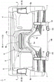
As shown in fig. 4, the bulkhead cross member 5 connects lower portions of the left and right hinge pillars 2 in the vehicle width direction along a lower end edge of the engine bulkhead 4. The bulkhead cross member 5 is formed in a substantially hat-shaped cross section projecting toward the vehicle front side in a longitudinal cross section along the vehicle front-rear direction, and forms a closed cross section together with the engine bulkhead 4, not shown in detail.
More specifically, as shown in fig. 4, the bulkhead cross member 5 is integrally formed, in front view, by a gate-shaped portion 5a that is substantially in the shape of a gate in front view and that protrudes upward in the vehicle so as to extend along the tunnel-corresponding portion 4a of the engine bulkhead 4, and a horizontally extending portion 5b that extends outward in the vehicle width direction from the lower end of the gate-shaped portion 5a toward each of the left and right hinge pillars 2.
As shown in fig. 4, the reinforcing member 6 is disposed as a reinforcing member for reinforcing the engine compartment 4 above the vehicle door-shaped portion 5a of the bulkhead cross member 5 in a front view. The reinforcement member 6 has an upper end joined to the windshield cowl 3 and a lower end joined to the door-shaped portion 5a of the bulkhead cross member 5.
More specifically, as shown in fig. 4, the reinforcing member 6 is integrally formed by a substantially gate-shaped reinforcing member main body 6a in a front view of the vehicle lower opening and a substantially flat plate portion 6b covering a portion surrounded by the reinforcing member main body 6 a.
As shown in fig. 5, the reinforcement member body 6a is formed in a cross-sectional shape protruding toward the vehicle front side in a longitudinal section along the vehicle front-rear direction, and a closed cross section is formed by the cowl lower 31 of the windshield cowl 3 and the engine compartment 4.
As shown in fig. 4 and 5, 2 ribs 6c that protrude forward of the vehicle and extend in the vehicle width direction are formed on the flat plate portion 6b at predetermined intervals in the vehicle vertical direction.
As shown in fig. 1 and 4, the torque box 7 is adjacent to the vehicle lower side of the horizontally extending portion 5b of the bulkhead cross member 5, and connects the side member 17 and the front side frame 10 in the vehicle width direction. The torque box 7 is formed in a substantially box shape having a closed cross section in a cross section along a longitudinal section in the vehicle longitudinal direction, together with the engine bulkhead 4 adjacent to the side member 17 on the vehicle width direction inner side, although not shown in detail.
As shown in fig. 2, the apron reinforcement 8 is a closed cross-section member formed in a shape extending substantially linearly in the vehicle front-rear direction when viewed in plan, and has a front end located inward in the vehicle width direction than a rear end.
As shown in fig. 2, the edge of the apron reinforcement 8 on the inside in the vehicle width direction is formed in a substantially arc shape in plan view so as to protrude inward in the vehicle width direction with the apex portion positioned at substantially the same position in the vehicle longitudinal direction as the damper attachment portion 121a of the suspension cover 12 described later.
More specifically, as shown in fig. 1 and 3, the apron reinforcement 8 is composed of an apron reinforcement rear part 81 whose rear end is joined to the upper part of the hinge pillar 2, and an apron reinforcement front part 82 joined to the apron reinforcement rear part 81.
As shown in fig. 2 and 3, the apron reinforcement rear portion 81 is formed to have a length in the vehicle front-rear direction in which the front end is positioned slightly behind the rear end of the suspension cover 12, which will be described later, in the vehicle. As shown in fig. 5, the apron reinforcement rear portion 81 is formed such that a cross-sectional shape of a vertical cross-section along the vehicle width direction is a closed cross-sectional shape.
As shown in fig. 3, the apron reinforcement front portion 82 is formed in a curved shape such that the lower surface forms a wheel arch with respect to a substantially horizontal upper surface when viewed from the side. As shown in fig. 6 and 7, the skirt reinforcement front portion 82 has a closed cross-sectional shape having a substantially rectangular cross-section in a longitudinal cross-section along the vehicle width direction, and includes a skirt reinforcement upper member 821 disposed above the vehicle and a skirt reinforcement lower member 822 disposed below the skirt reinforcement upper member 821 in the vehicle.
Specifically, as shown in fig. 6, the apron reinforcement upper 821 has a cross-sectional shape in which a vertical cross-section along the vehicle width direction is formed in a substantially hat-shaped cross-section projecting upward of the vehicle.
On the other hand, as shown in fig. 6 and 7, the skirt reinforcement lower 822 is formed so that its cross-sectional shape in a vertical cross section along the vehicle width direction is substantially hat-shaped in cross section protruding downward of the vehicle.
As shown in fig. 7, the apron reinforcement lower 822 is integrally formed by sequentially joining an apron reinforcement component 124 integrally formed with the suspension cover 12 and a steel lower plate 823 formed in a shape continuous from the apron reinforcement component 124 from the vehicle rear side. The details of the apron reinforcement forming portion 124 will be described later.
As shown in fig. 8, the cross-sectional shape of the hood upper side member 9 in a longitudinal section along the vehicle front-rear direction is a closed cross-sectional member having a closed cross-section, and is composed of a hood lower plate 91 having a substantially hat-shaped cross-section and projecting downward of the vehicle, and a hood upper plate 92 having a substantially hat-shaped cross-section and projecting upward of the vehicle.
As shown in fig. 3 and 9, the front side frame 10 is a closed cross-sectional member having a length in the vehicle longitudinal direction from the lower portion of the engine bulkhead 4 to the front end of the apron reinforcement 8.
As shown in fig. 9, the rear end of the front side frame 10 is joined to the floor frame 19 over a range from the front end thereof to the bulkhead cross member 5, and the floor frame 19 forms a closed cross section extending in the vehicle front-rear direction together with the floor (not shown). Further, the vehicle width direction inner side of the torque box 7 is joined to the vehicle width direction outer side surface of the front side frame 10.
More specifically, as shown in fig. 6, 10, and 11, the cross-sectional shape of the longitudinal section of the front side frame 10 along the vehicle width direction is a closed cross-sectional shape having a substantially rectangular cross-section, and is composed of a side frame inner 101 disposed on the vehicle width direction inner side and a side frame outer 102 disposed on the vehicle width direction outer side with respect to the side frame inner 101.
As shown in fig. 10, the side frame inner 101 is formed in a shape in which a substantially hat-shaped open cross section protruding inward in the vehicle width direction extends in the vehicle front-rear direction.
On the other hand, as shown in fig. 11, the side frame outer 102 is formed in a shape in which a substantially hat-shaped open cross section protruding outward in the vehicle width direction is extended in the vehicle front-rear direction, at a length in the vehicle width direction longer than that of the side frame inner 101.
As shown in fig. 1, a substantially flat plate member 103 having a closed front end opening and a crush can, not shown, connected thereto is joined to the front side frame 10.
Further, as shown in fig. 12 and 13, a 1 st joint member 104, a 2 nd joint member 105, and a 3 rd joint member 106 are disposed in this order from the front of the vehicle inside the front side frame 10 so as to partition the interior space at positions spaced apart by a predetermined interval in the vehicle front-rear direction.
As shown in fig. 12 and 14, the 1 st-stage member 104 is integrally formed by a substantially flat plate portion having a predetermined thickness in the vehicle front-rear direction and a flange portion extending in a flange shape from an edge end of the flat plate portion.
As shown in fig. 12 and 14, the 1 st link 104 is disposed at substantially the same position in the vehicle longitudinal direction as the lower end rear portion of the hood member 11 described later, and is joined to the inner surface of the front side frame 10. Therefore, a closed cross-sectional space continuous with a hood member 11 described later is formed inside the front side frame 10 by the flat plate member 103 and the 1 st segment member 104.
As shown in fig. 12, the 2 nd-stage member 105 is integrally formed by a substantially flat plate portion having a predetermined thickness in the vehicle front-rear direction and a flange portion extending in a flange shape from an edge end of the plate portion. The 2 nd joint member 105 is disposed at a position separated from the 1 st joint member 104 by a predetermined distance toward the rear of the vehicle.
As shown in fig. 13, the 3 rd-stage member 106 is integrally formed by a substantially flat plate portion having a predetermined thickness in the vehicle front-rear direction and a flange portion extending in a flange shape from an edge end of the flat plate portion. As shown in fig. 13, the 3 rd-stage member 106 is joined to the inner surface of the front side frame 10 so as to connect a rear reinforcing portion 123 of the suspension case 12, which will be described later, and a rear connecting member 16, which will be described later, in the vehicle vertical direction.
As shown in fig. 10, 11, and 15, the hood member 11 is a closed-section member having a closed section whose cross section along a horizontal section in the vehicle longitudinal direction is substantially rectangular in cross section, and is configured from an inner side surface constituting portion 111 disposed on the inner side in the vehicle width direction, an outer side surface constituting portion 112 disposed on the outer side in the vehicle width direction with respect to the inner side surface constituting portion 111, and a front surface constituting portion 113 disposed on the vehicle front side of the inner side surface constituting portion 111.
Specifically, as shown in fig. 10 and 15, the inner side surface constituting portion 111 is integrally formed by an inner side surface portion 111a which becomes a side surface on the inside in the vehicle width direction of the cowl member 11, a rear surface portion 111b which becomes a rear surface of the cowl member 11, a front side flange portion 111c which extends outward in the vehicle width direction from a front end of the inner side surface portion 111a, a rear side flange portion 111d which extends rearward in the vehicle width direction from an outer side in the vehicle width direction of the rear surface portion 111b, and a lower side flange portion 111e which extends rearward in the vehicle from a lower end of the rear surface portion 111 b.
As shown in fig. 10 and 12, the lower end of the inner surface portion 111a of the inner surface constituting portion 111 is joined to the flange portion of the side frame outer 102, and the lower flange portion 111e is joined to the 1 st joint member 104 via the upper surface of the side frame outer 102.
As shown in fig. 11 and 15, the outer side surface constituting portion 112 is integrally formed of a bulging portion 112a bulging outward in the vehicle width direction than a side surface on the vehicle width direction outer side of the side frame outer 102, a rear side flange portion 112b provided in a substantially flange shape along a lower end edge and a rear end edge of the bulging portion 112a, and a front side flange portion 112c extending outward in the vehicle width direction from a front end edge of the bulging portion 112 a.
The bulging portion 112a of the outer side surface constituting portion 112 is formed with a length in the vehicle vertical direction from the upper end to the side surface of the front side frame 10. Further, the lower portion of the rear flange portion 112b of the outer side surface constituent portion 112 is joined to the side frame outer 102, the rear portion of the rear flange portion 112b is joined to the rear flange portion 111d of the inner side surface constituent portion 111, and the front flange portion 112c is joined to the front surface constituent portion 113.
As shown in fig. 10, 11, 14, and 15, the front surface constituting portion 113 is formed in a substantially flat plate shape having a predetermined thickness in the vehicle front-rear direction, and is formed in a shape that closes the opening on the vehicle front side formed by the inner side surface constituting portion 111 and the outer side surface constituting portion 112.
Therefore, as shown in fig. 14 and 15, in a horizontal cross section along the vehicle longitudinal direction, the cowl member 11 is formed in a closed cross section by the inner side surface constituting portion 111, the outer side surface constituting portion 112, and the front surface constituting portion 113 on the vehicle upper side with respect to the upper surface of the front side frame 10, and is formed in a closed cross section by the outer side surface constituting portion 112, the front surface constituting portion 113, and the side surface of the front side frame 10 on the vehicle lower side with respect to the upper surface of the front side frame 10.
That is, in the cowl member 11, the outer side surface constituent portion 112 and the front surface constituent portion 113 form a closed cross-sectional portion as a closed cross section together with the front side frame 10, thereby forming a closed cross-sectional space adjacent to the closed cross-sectional space of the front side frame 10 partitioned by the flat plate member 103 and the 1 st segment member 104.
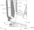
As shown in fig. 1 and 3, the suspension shell 12 is a high-rigidity member that swingably supports the upper end and the upper arm 21 of the front suspension damper 20 disposed at a desired position in the vehicle front with respect to the hinge pillar 2 and the engine bulkhead 4, and is bridged across the apron reinforcement 8 and the front side frame 10.
More specifically, as shown in fig. 3 and 16, the suspension shell 12 is integrally formed by a suspension tower cover 121 to which the upper end of the front suspension damper 20 is attached, a front reinforcement portion 122 adjacent to the vehicle front side of the suspension tower cover 121, a rear reinforcement portion 123 adjacent to the vehicle rear side of the suspension tower cover 121, and a skirt reinforcement constituting portion 124 that becomes a part of a skirt reinforcement lower member 822 of the skirt reinforcement 8.
As shown in fig. 3, the lower end of the suspension housing 12 is engaged with a flange portion of the side frame outer 102 in the front side frame 10. As shown in fig. 3, the lower end of the rear reinforcing portion 123 of the suspension housing 12 is joined to the flange portion of the side frame outer 102 of the front side frame 10 at substantially the same position in the vehicle longitudinal direction as the upper base portion 163 of the rear connecting member 16 described later.
As shown in fig. 13 and 16, the suspension tower cover 121 is formed of a substantially circular tower top portion in plan view, and a side portion extending downward of the vehicle from a vehicle width direction inside edge end of the tower top portion to become a vehicle width direction inside side surface. A substantially circular damper attachment portion 121a is formed at the tower top portion of the suspension tower cover 121 to attach the upper end of the front suspension damper 20.
As shown in fig. 13 and 16, the front reinforcing portion 122 is formed as a reinforcing portion that reinforces the vehicle front side of the suspension tower cover 121. The front reinforcing portion 122 is formed in a shape bulging inward in the vehicle width direction in a range from a position substantially in the vehicle vertical direction with respect to the tower top portion of the suspension tower cover 121 to a lower portion of the suspension housing 12.
As shown in fig. 13 and 16, the rear reinforcing portion 123 is formed as a reinforcing portion that reinforces the vehicle rear side of the suspension tower 121. The rear reinforcing portion 123 is formed in a shape bulging inward in the vehicle width direction in a range from a position above the tower top portion of the suspension tower 121 in the vehicle to a lower portion of the suspension housing 12.
As shown in fig. 7, 16, and 17, the skirt reinforcement forming portion 124 is formed in a shape in which upper ends of the suspension tower cover 121, the front reinforcement portion 122, and the rear reinforcement portion 123 are integrally extended outward in the vehicle width direction, and forms a closed cross section extending in the vehicle front-rear direction together with the skirt reinforcement upper member 821 of the skirt reinforcement 8.
Specifically, the apron reinforcement constituent portion 124 is formed such that, in a state of being joined to the lower plate 823 of the apron reinforcement 8, the cross-sectional shape of the vertical cross section along the vehicle width direction is a substantially hat-shaped cross section that protrudes downward of the vehicle, continuing from the lower plate 823.
As shown in fig. 3, 13, and 17, on the vehicle width direction outer side surface of the suspension housing 12 configured as described above, a front side support 125 that swingably supports the front side connecting portion of the upper arm 21 and a rear side support 126 that swingably supports the rear side connecting portion of the upper arm 21 are formed at positions in the vehicle front-rear direction across the suspension tower cover 121.
The front side support portion 125 is formed in a pair of wall surfaces that are erected toward the vehicle width direction outer side along both ends in the vehicle front-rear direction in the front reinforcing portion 122.
The rear support portion 126 is formed in a pair of wall surfaces that are erected toward the vehicle width direction outer side along both ends in the vehicle front-rear direction in the rear reinforcing portion 123.
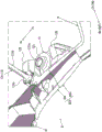
As shown in fig. 2 and 5, the tower cover rod 13 connects the upper surfaces of the rear reinforcing portions 123 of the left and right suspension housings 12 to each other via the windshield cowl 3.
Specifically, as shown in fig. 2 and 5, the tower cover lever 13 includes a tubular lever main body 131 that connects the rear reinforcing portions 123 of the left and right suspension housings 12, and a holding member 132 that holds the rear end of the lever main body 131 and is connected to the windshield mold 3.
As shown in fig. 2, 5, and 7, the lever main body 131 is integrally formed in a substantially V-shape in plan view by a pair of left and right flange portions 131a connected to the rear reinforcing portion 123 of the suspension cover 12, a pair of left and right long portions 131b extending substantially linearly from the flange portions 131a toward the vicinity of the substantially center in the vehicle width direction in the windshield cowl 3 rearward of the vehicle and inward in the vehicle width direction, and a connecting portion 131c connecting rear ends of the long portions 131 b.
As shown in fig. 1, 2, and 5, the holding member 132 is formed in a shape that integrally holds the vicinity of the rear end of the left and right long portions 131b and the connecting portion 131c, and is formed in a shape that can be joined to the upper surface of the gate-shaped portion 5a of the reinforcing member 6.
As shown in fig. 5, the tower bar 13 is connected to the cowl 3 as a closed cross-section member via the reinforcing member 6 that forms a closed cross-section together with the engine bulkhead 4 and the cowl 3 by joining the holding member 132 to the upper surface of the door-shaped portion 5a of the reinforcing member 6.
As shown in fig. 18, the sub-frame 14 is formed in a substantially ladder-like shape in plan view from a pair of left and right side members 141 extending in the vehicle longitudinal direction at positions spaced apart by a predetermined distance in the vehicle width direction, a front side suspension cross member 142 connecting the left and right side members 141 in the vehicle width direction, a center suspension cross member 143, and a rear side suspension cross member 144.
More specifically, as shown in fig. 2, the side member 141 is disposed slightly inward of the front side frame 10 in the vehicle width direction in plan view.
As shown in fig. 18, side member 141 is a closed cross-sectional member having a closed cross-section whose cross-sectional shape along the longitudinal cross-section in the vehicle width direction is substantially rectangular in cross-section, and is formed in a shape having a length in the vehicle front-rear direction substantially equal to the length in the vehicle front-rear direction in front side frame 10.
As shown in fig. 18, the front end and the rear end of side member 141 are each formed in a shape curved outward in the vehicle width direction.
As shown in fig. 18, a front support bracket 145 that swingably supports the connecting portion on the vehicle front side in the lower arm 22 is joined to a portion further toward the vehicle front side than a rear connecting member 16 described later on the side member 141, and a rear support bracket 146 that swingably supports the connecting portion on the vehicle rear side in the lower arm 22 is fastened to a portion further toward the vehicle rear side than the rear connecting member 16.
As shown in fig. 9 and 18, an insertion hole (not shown) through which a fastening member 147 fixed to the lower surface of the rear end of the front side frame 10 is inserted is formed in the upper rear end opening of the side member 141.
As shown in fig. 18, a front side suspension cross member 142 connects front ends of side members 141 in the vehicle width direction. As shown in fig. 18, the front suspension cross member 142 is a closed cross-sectional member having a closed cross-sectional shape in a longitudinal cross section along the vehicle longitudinal direction, and is composed of a substantially hat-shaped cross-sectional member protruding upward of the vehicle and a substantially flat plate-shaped cross-sectional member.
As shown in fig. 18, the center suspension cross member 143 connects the left and right side members 141 in the vehicle width direction at a position spaced apart from the front suspension cross member 142 by a predetermined distance toward the vehicle rear. The central suspension cross member 143 has a shape having a rear closed cross-section portion 143a and a front closed cross-section portion 143b, the rear closed cross-section portion 143a being a closed cross-section portion connecting the left and right side members 141 at substantially the same position in the vehicle front-rear direction as the rear reinforcing portion 123 of the suspension housing 12, and the front closed cross-section portion 143b being a closed cross-section portion connecting the left and right side members 141 at a position separated from the rear closed cross-section portion 143a toward the vehicle front.
Specifically, as shown in fig. 18, the central suspension cross member 143 is formed by joining a substantially H-shaped beam upper member and a substantially flat plate-shaped beam lower member in the vehicle vertical direction in a plan view that protrude upward of the vehicle and are open outward in the vehicle width direction, thereby forming a closed cross-section rear portion 143a that is a closed cross-section portion extending in the vehicle width direction on the vehicle rear side and a closed cross-section front portion 143b that is a closed cross-section portion extending in the vehicle width direction on the vehicle front side.
As shown in fig. 18, rear suspension cross member 144 connects the rear ends of side members 141 in the vehicle width direction. As shown in fig. 18, the rear suspension cross member 144 is a closed cross-sectional member having a closed cross-sectional shape in a longitudinal cross section along the vehicle front-rear direction, and is composed of a substantially hat-shaped cross-sectional member protruding upward of the vehicle and a substantially flat plate-shaped cross-sectional member.
As shown in fig. 11, 12, and 18, the pair of left and right front connecting members 15 are formed in a shape in which a substantially rectangular closed cross section extends upward of the vehicle and outward in the vehicle width direction, and then extends outward in the vehicle width direction. As shown in fig. 12, the front connecting member 15 connects the lower surface of the side frame outer 102 of the front side frame 10 and the front side suspension cross member 142 of the sub-frame 14 in the vehicle vertical direction at substantially the same position in the vehicle longitudinal direction as the lower end of the cowl member 11.
More specifically, as shown in fig. 11, 12, and 18, the front connecting member 15 has a closed cross-sectional shape having a substantially rectangular cross-section in a longitudinal cross-section along the vehicle longitudinal direction, and is configured by joining a substantially portal-shaped cross-sectional beam upper side member having a vehicle lower opening and a substantially portal-shaped cross-sectional beam lower side member having a vehicle upper opening in the vehicle vertical direction.
As shown in fig. 12 and 18, the front connecting member 15 is integrally provided with a fastening member 151 for fastening to the front side frame 10 on the upper surface on the outer side in the vehicle width direction.
As shown in fig. 12, the front connecting member 15 is fastened to the lower surface of the side frame outer 102 via a fastening member 151 between the flat plate member 103 and the 1 st joint member 104 in the vehicle longitudinal direction such that the upper surface on the vehicle width direction outer side faces the cowl member 11 in the vehicle vertical direction.
As shown in fig. 3 and 13, the rear connecting member 16 connects the lower surface of the side frame outer 102 of the front side frame 10 and the side member 141 of the sub-frame 14 in the vehicle vertical direction at substantially the same position in the vehicle vertical direction as the rear reinforcing portion 123 of the suspension cover 12.
In other words, as shown in fig. 13, the rear coupling member 16 couples the lower surface of the side frame outer 102 of the front side frame 10 and the side member 141 of the sub-frame 14 in the vehicle vertical direction at substantially the same position in the vehicle vertical direction as the 3 rd joint member 106 provided inside the front side frame 10.
As shown in fig. 18, the rear coupling member 16 is a high-rigidity member made of aluminum die-cast, and is integrally formed with a lower base portion 161 fastened to the side member 141, an accommodating and holding portion 162 for accommodating and holding an engine mount bushing (not shown), and an upper base portion 163 provided with a fastening member 164 fastened to the front side frame 10.
As shown in fig. 18, the housing and holding portion 162 is formed in a substantially cylindrical shape extending from the lower base portion 161 toward the vehicle upper side and the vehicle width direction inner side. The housing and holding portion 162 is configured to be able to house therein an engine mount bushing that elastically supports an engine (not shown).
As shown in fig. 13, the upper base 163 is integrally formed on the vehicle width direction outer side of the housing holder 162 so as to be located at substantially the same position in the vehicle front-rear direction as the 3 rd joint member 106 in a state fastened to the sub-frame 14.
As shown in fig. 19 to 22, in the front vehicle body of the vehicle 1 configured as described above, a plurality of annular vehicle body frames forming a substantially annular shape are formed by connecting the members configuring the vehicle body frames to each other, and a plurality of annular vehicle body frames are connected to each other to form a substantially annular three-dimensional annular vehicle body frame three-dimensionally.
Specifically, as shown in fig. 19 to 21, the front vehicle body of the vehicle 1 is formed with a 1 st annular vehicle body frame W1 formed into a substantially annular shape through the hood upper side member 9, a 2 nd annular vehicle body frame W2 formed into a substantially annular shape through the suspension shell 12, a 3 rd annular vehicle body frame W3 formed into a substantially annular shape through the bulkhead cross member 5, a 4 th annular vehicle body frame W4 formed into a substantially annular shape through the bulkhead cross member 5 and the sub-frame 14, and a 5 th annular vehicle body frame W5 formed into a substantially annular shape through the torque box 7 and the sub-frame 14, as viewed from the front.
As shown in fig. 22, a 6 th annular body frame W6 formed in a substantially annular shape through the apron reinforcement 8 and a 7 th annular body frame W7 formed in a substantially annular shape through the sub-frame 14 are formed in the front vehicle body of the vehicle 1 in a side view.
The front body of the vehicle 1 is connected by the left and right apron reinforcements 8, the left and right front side frames 10, and the left and right side sills 141 of the sub-frame 14, so that the 1 st, 2 nd, 3 rd, 4 th, and 5 th annular body frames W1, W2, W3, W4, and W5 are connected to each other via the 6 th and 7 th annular body frames W6 and W7, which are substantially annular when viewed from the front.
Specifically, as shown in fig. 19, the 1 st annular vehicle body frame W1, which is substantially annular in front view, is configured by the hood upper side member 9 as a closed cross-section member, the front side frame 10 as a closed cross-section member surrounded by the flat plate member 103 and the 1 st link member 104, the left and right hood members 11 as closed cross-section members, the front side suspension cross member 142 as the sub-frame 14 as a closed cross-section member, and the left and right front connecting members 15 as closed cross-section members.
As shown in fig. 20, the 2 nd annular vehicle body frame W2, which is substantially annular in front view, is configured by left and right front side frames 10 as closed cross-section members including the 3 rd link member 106, rear reinforcing portions 123 of left and right suspension housings 12 as high-rigidity members, a tower cover rod 13 as a closed cross-section member, a rear closed cross-section portion 143a in the central suspension cross member 143 of the sub-frame 14 as a closed cross-section member, and left and right rear connecting members 16 as high-rigidity members.
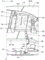
As shown in fig. 21, the 3 rd annular vehicle body frame W3, which is substantially annular in front view, is configured by left and right hinge pillars 2 as closed-section members, a cowl 3 as a closed-section member, and a bulkhead cross member 5 that forms a closed section extending in the vehicle width direction together with the engine bulkhead 4.
As shown in fig. 21, the 4 th annular vehicle body frame W4, which is substantially annular in front view, is configured by left and right hinge pillars 2 as closed-section members, a windshield cowl 3 as a closed-section member, a horizontal extension 5b of a bulkhead cross member 5 that forms a closed section together with the engine bulkhead 4, left and right front side frames 10 as closed-section members, side frames 141 as sub-frames 14 as closed-section members, and a rear suspension cross member 144.
As shown in fig. 21, the 5 th annular vehicle body frame W5, which is substantially annular in front view, is configured by left and right hinge pillars 2 as closed-section members, a windshield cowl 3 as a closed-section member, a torque box 7 that forms a closed section together with the engine bulkhead 4, left and right front side frames 10 as closed-section members, side members 141 as sub-frames 14 as closed-section members, and a rear suspension cross member 144.
As shown in fig. 22, the 6 th annular body frame W6, which is substantially annular in side view, is constituted by the hinge pillar 2 as a closed cross-section member, the bulkhead cross member 5 constituting a closed cross-section together with the engine bulkhead 4, the apron reinforcement 8 as a closed cross-section member, the front side frame 10 as a closed cross-section member, and the cowl member 11 as a closed cross-section member.
As shown in fig. 22, the 7 th annular body frame W7, which is substantially annular in side view, is configured by the front side frame 10 as a closed-section member, the side member 141 as the sub-frame 14 as a closed-section member, and the front connecting member 15 as a closed-section member.
In this manner, in the front vehicle body of the vehicle 1, the 1 st, 2 nd, 3 rd, 4 th, and 5 th annular vehicle body frames W1, W2, W3, W4, and W5, which are formed in a substantially annular shape in front view at positions spaced apart by a predetermined interval in the vehicle front-rear direction, are coupled in the vehicle front-rear direction by the 6 th and 7 th annular vehicle body frames W6 and W7, which are formed in a substantially annular shape in side view.
Therefore, in the front vehicle body of the vehicle 1, the 1 st, 2 nd, 3 rd, 4 th, and 5 th annular vehicle bodies W1, W2, W3, W4, and W5, which are substantially annular in front view, and the 6 th and 7 th annular vehicle bodies W6, W7, which are substantially annular in side view, form a substantially cage-shaped three-dimensional annular vehicle body frame.
As described above, the front vehicle body structure of the vehicle 1 includes: a pair of left and right hinge pillars 2 arranged at positions spaced apart by a predetermined interval in a vehicle width direction of the vehicle 1; a pair of left and right apron reinforcements 8 which are closed-section members extending in the vehicle front-rear direction from the upper portion of the hinge pillar 2; a pair of left and right front side frames 10 which are closed cross-sectional members extending in the vehicle front-rear direction below the apron reinforcement 8 in the vehicle; a pair of left and right suspension cases 12 that support the upper end of the front suspension damper 20 at a desired position spaced apart from the engine bulkhead 4 by a predetermined distance toward the vehicle front, and that span across the apron reinforcement 8 and the front side frame 10; a sub-frame 14 disposed below the front side frame 10 in the vehicle and supporting a lower arm 22 in a freely swinging manner, and the front vehicle body structure of the vehicle 1 further includes: a cowl top 9 which is a closed-section member that connects the front ends of the apron reinforcement 8 in the vehicle width direction; the pair of left and right head covering members 11 are closed cross-section members that connect the front ends of the head cover upper 9 and the front side frame 10, and the sub-frame 14 includes: a pair of left and right side members 141 along the vehicle front-rear direction; a front suspension cross member 142 that is a closed cross-section member connecting the left and right side members 141 at substantially the same position in the vehicle front-rear direction as the cowl member 11; and a center suspension cross member 143 that is a closed cross-section member connecting the left and right side members 141 at substantially the same position in the vehicle front-rear direction as the suspension housing 12, and the front vehicle body structure of the vehicle 1 includes: the 1 st annular vehicle body frame W1 which is substantially annular in front view passing through the hood member 11 and the front side suspension cross member 142 of the sub-frame 14, the 2 nd annular vehicle body frame W2 which is substantially annular in front view passing through the vicinity of the suspension cover 12 and the center suspension cross member 143 of the sub-frame 14, and the 3 rd annular vehicle body frame W3 which is substantially annular in front view passing through the hinge pillar 2 are coupled in the vehicle front-rear direction by the apron reinforcement 8, the front side frame 141, and the side member of the sub-frame 14, whereby the vehicle body rigidity with respect to the load acting on the suspension cover 12 and the load acting on the sub-frame 14 can be improved even when the suspension cover 12 is disposed at a position separated toward the vehicle front with respect to the engine compartment 4.
Specifically, the 1 st annular body frame W1, the 2 nd annular body frame W2, and the 3 rd annular body frame W3 are connected by the apron reinforcement 8, the front side frame 10, and the side member 141 of the sub-frame 14, whereby the front body structure of the vehicle 1 can be configured as a substantially annular three-dimensional annular body frame in three dimensions.
Accordingly, the front vehicle body structure of the vehicle 1 can support the left and right suspension housings 12 by the three-dimensional substantially annular three-dimensional annular vehicle body frame, and therefore, when a load in the vehicle vertical direction, a load in the vehicle width direction, or a rotational moment acts on the suspension housings 12 via the front suspension dampers 20, it is possible to suppress flexural deformation of the front vehicle body.
Therefore, the front body structure of the vehicle 1 can constitute a highly rigid body frame with respect to the load in the vehicle vertical direction, the load in the vehicle width direction, and the rotational moment acting on the suspension housing 12 via the front suspension damper 20.
Further, since the front side suspension cross member 142 constitutes the 1 st annular vehicle body frame W1, the center suspension cross member 143 constitutes the 2 nd annular vehicle body frame W2, and the side member 141 is coupled to the 3 rd annular vehicle body frame W3, the front vehicle body structure of the vehicle 1 can improve the support rigidity of the sub-frame 14, and can efficiently disperse and transmit the load applied to the sub-frame 14 via the lower arm 22 to the 1 st annular vehicle body frame W1, the 2 nd annular vehicle body frame W2, the 3 rd annular vehicle body frame W3, the apron reinforcement 8, and the front side frame 10.
Therefore, in the front vehicle body structure of the vehicle 1, when the suspension housing 12 is disposed at a position separated from the engine compartment 4 toward the vehicle front side, the load applied to the suspension housing 12 and the load applied to the sub-frame 14 can be increased in vehicle body rigidity.
Further, the 2 nd annular body frame W2 is provided on the vehicle rear side of the suspension housing 12, whereby the front vehicle body structure of the vehicle 1 can bring the 2 nd annular body frame W2 close to the 3 rd annular body frame W3. Therefore, the front vehicle body structure of the vehicle 1 can efficiently transmit the load applied to the 2 nd annular vehicle body frame W2 to the vehicle body behind the 3 rd annular vehicle body frame W3 and the 3 rd annular vehicle body frame W3.
Thus, the front vehicle body structure of the vehicle 1 can stably improve the vehicle body rigidity with respect to the load applied to the suspension cover 12 and the load applied to the sub-frame 14, as compared with the case where the 2 nd annular vehicle body frame W2 is provided on the vehicle front side of the suspension cover 12.
Further, the 3 rd annular body frame W3 includes the windshield cowl 3, the windshield cowl 3 being a closed cross-section member that connects the upper portions of the hinge pillars 2 in the vehicle width direction, and the 2 nd annular body frame W2 includes the tower cover rod 13, and the tower cover rod 13 connects the left and right suspension housings 12 via the vicinity of the substantially center of the windshield cowl 3 in the vehicle width direction, whereby the front body structure of the vehicle 1 can form a substantially triangular shape in the vehicle width direction by the windshield cowl 3, the left and right apron reinforcements 8, and the tower cover rod 13, that is, the front body structure of the vehicle 1 can form a truss structure at the rear of the front body by the windshield cowl 3, the left and right apron reinforcements 8, and the tower cover rod 13.
In this case, the tower bar 13 constituting the 2 nd annular body frame W2 is coupled to the windshield cowl 3 constituting the 3 rd annular body frame W3, and the front body structure of the vehicle 1 can more reliably improve the rigidity of the substantially annular three-dimensional annular body frame configured in a three-dimensional manner by the cooperation of the 3 rd annular body frame W3 and the 2 nd annular body frame W2.
Further, since the tower cover 13 is formed in a substantially splayed shape in a vehicle front view, a large opening space can be formed between the left and right apron reinforcements 8 and in the vehicle front of the tower cover 13 without sacrificing vehicle body rigidity in a front vehicle body structure of the vehicle 1 in a plan view, as compared with a case where the left and right suspension housings 12 are coupled in the vehicle width direction.
Therefore, the front body structure of the vehicle 1 can achieve both the securing of the arrangement space of the engine and the like disposed in the front body and the improvement of the body rigidity with respect to the load applied to the suspension housing 12 and the load applied to the sub-frame 14.
In the configuration of the present invention and the correspondence between the above-described embodiments, the suspension arm of the present invention corresponds to the lower arm 22 of the embodiment, and hereinafter, similarly, the 1 st suspension cross member corresponds to the front suspension cross member 142, the 2 nd suspension cross member corresponds to the center suspension cross member 143, and the suspension shell coupling member corresponds to the tower cover rod 13.
For example, in the above-described embodiment, the cowl member 11 is joined to the vehicle width direction outer side surface and the upper surface of the front side frame 10, but is not limited thereto, and may be joined to both vehicle width direction side surfaces and the upper surface of the front side frame 10.
Further, the rear end of the tower bar 13 is connected to the windshield wiper 3, but the present invention is not limited to this, and for example, the rear end of the tower bar 13 may be connected to a bulkhead cross member, the rear end of the tower bar 13 may be adjacent to the windshield wiper 3, connect the left and right hinge pillars 2 in the vehicle width direction, and form a closed cross section together with the engine bulkhead 4.
Further, the rear end of the tower cover rod 13 is coupled to the windshield cowl 3 via the reinforcing member 6, but the present invention is not limited thereto, and the rear end of the tower cover rod 13 may be directly joined to the windshield cowl 3.
Further, the left and right long portions 131b in the lever main body 131 of the tower bar 13 are coupled to the windshield cowl 3 via the coupling portions 131c and the holding member 132, but the present invention is not limited to this, and the rear ends of the left and right long coupling members configured separately may be coupled to the windshield cowl 3 as a pair of left and right long coupling members configured by the flange portion 131a and the long portion 131 b.
Further, the rear coupling member 16 includes the housing and holding portion 162 housing and holding the engine mount bushing therein, but is not limited to this, and an integrally assembled coupling member including a mounting portion on which the engine mount bushing is mounted and fixed may be employed.
The reinforcing portion is formed in a shape that bulges the front reinforcing portion 122 and the rear reinforcing portion 123 of the suspension housing 12 inward in the vehicle width direction, but is not limited to this, and a reinforcing portion that extends in the vehicle vertical direction and is configured by a plurality of ribs standing toward the vehicle width direction inner side may be employed.
Further, the suspension housing 12 may be an aluminum die-cast suspension housing or a suspension housing formed by press-forming a steel plate. In the case of a suspension shell formed by press-forming a steel plate, the front reinforcing portion and the rear reinforcing portion of the suspension shell are formed by an open cross-sectional member that forms a closed cross-section extending in the vehicle vertical direction with the suspension tower cover.
Further, although 13 rd node member 106 is provided in the internal space of the front side frame 10 between the suspension case 12 and the rear coupling member 16, the present invention is not limited to this, and 2 node members may be arranged in the internal space of the front side frame 10 between the suspension case 12 and the rear coupling member 16 at predetermined intervals in the vehicle front-rear direction.
Further, although the 3 rd annular vehicle body frame W3 is described as the annular vehicle body frame connected to the 1 st annular vehicle body frame W1 and the 2 nd annular vehicle body frame W2 via the apron reinforcement 8, the front side frame 10, and the side member 141 of the sub-frame 14, the present invention is not limited to this, and the 4 th annular vehicle body frame W4 or the 5 th annular vehicle body frame W5 may be the annular vehicle body frame connected to the 1 st annular vehicle body frame W1 and the 2 nd annular vehicle body frame W2. Alternatively, the 3 rd, 4 th, and 5 th annular vehicle bodies W3, W4, and W5 may be annular vehicle bodies connected to the 1 st and 2 nd annular vehicle bodies W1, W2.
Claims (3)
1. A front vehicle body structure of a vehicle, comprising:
a pair of left and right hinge pillars arranged at positions spaced apart by a predetermined distance in a vehicle width direction of a vehicle;
a pair of left and right apron plate reinforcements that are closed-section members extending in the vehicle front-rear direction from the upper portions of the hinge pillars;
a pair of left and right front side frames which are closed cross-sectional members extending in a vehicle front-rear direction below the apron reinforcement in the vehicle;
a pair of left and right suspension cases that support the upper end of a front suspension damper at a desired position spaced apart from an engine bulkhead by a predetermined distance toward the front of the vehicle and that span the apron reinforcement and the front side frame; and
a sub-frame disposed below the front side frame with respect to the vehicle and supporting a suspension arm in a swingable manner,
the front vehicle body structure of the vehicle is characterized by further comprising:
a cowl top side member that is a closed cross-section member that connects the front ends of the apron reinforcement members in the vehicle width direction; and
a pair of left and right head cover members which are closed cross-section members connecting the head cover upper member and the front end of the front side frame,
the sub-frame includes:
a pair of left and right side members extending in the vehicle front-rear direction;
a 1 st suspension cross member that is a closed cross-section member that connects the left and right side members at substantially the same position in the vehicle front-rear direction as the cowl member; and
a 2 nd suspension cross member that is a closed cross-section member connecting the left and right side members at substantially the same position in the vehicle front-rear direction as the suspension housing,
the front vehicle body structure of the vehicle is provided with:
a 1 st annular vehicle body frame that is substantially annular in front view passing through the cowl member and the 1 st suspension cross member of the sub-frame;
a 2 nd annular vehicle body frame passing through the vicinity of the suspension cover and the 2 nd suspension cross member of the sub-frame and forming a substantially annular shape in front view; and
a 3 rd ring-shaped vehicle body frame passing through the hinge pillar and formed into a substantially ring shape in front view,
the 1 st, 2 nd and 3 rd annular body frames are connected in the vehicle front-rear direction by the side members of the apron reinforcement, the front side frame and the sub frame.
2. A front vehicle body structure of a vehicle according to claim 1,
the 2 nd annular body frame is provided on the vehicle rear side of the suspension housing.
3. A front vehicle body structure of a vehicle according to claim 1 or 2,
the 3 rd annular vehicle body frame includes a louver cowl, which is a closed cross-section member connecting upper portions of the hinge pillars in the vehicle width direction,
the 2 nd annular vehicle body frame includes a suspension casing coupling member that couples the left and right suspension casings via a vicinity of a substantially center in a vehicle width direction of the windshield mold.
Applications Claiming Priority (2)
| Application Number | Priority Date | Filing Date | Title |
|---|---|---|---|
| JP2018155731A JP6973329B2 (en) | 2018-08-22 | 2018-08-22 | Vehicle front body structure |
| JP2018-155731 | 2018-08-22 |
Publications (1)
| Publication Number | Publication Date |
|---|---|
| CN110857126A true CN110857126A (en) | 2020-03-03 |
Family
ID=67620267
Family Applications (1)
| Application Number | Title | Priority Date | Filing Date |
|---|---|---|---|
| CN201910759061.9A Pending CN110857126A (en) | 2018-08-22 | 2019-08-16 | Front vehicle body structure of vehicle |
Country Status (4)
| Country | Link |
|---|---|
| US (1) | US11084532B2 (en) |
| EP (1) | EP3613653B1 (en) |
| JP (1) | JP6973329B2 (en) |
| CN (1) | CN110857126A (en) |
Families Citing this family (3)
| Publication number | Priority date | Publication date | Assignee | Title |
|---|---|---|---|---|
| JP7056302B2 (en) * | 2018-03-27 | 2022-04-19 | マツダ株式会社 | Vehicle front body structure |
| KR20220161967A (en) * | 2021-05-31 | 2022-12-07 | 현대자동차주식회사 | Body structure for mounting the suspension |
| CN115402413B (en) * | 2022-08-31 | 2023-07-14 | 东风汽车集团股份有限公司 | Car body suspension mounting structure and vehicle based on aluminium alloy |
Citations (14)
| Publication number | Priority date | Publication date | Assignee | Title |
|---|---|---|---|---|
| CN102161352A (en) * | 2010-02-15 | 2011-08-24 | 马自达汽车株式会社 | Lower structure of automotive vehicle |
| CN102343939A (en) * | 2010-06-28 | 2012-02-08 | 马自达汽车株式会社 | Lower vehicle-body structure of vehicle |
| CN102963436A (en) * | 2011-08-29 | 2013-03-13 | 三菱自动车工业株式会社 | Vehicle strut tower support reinforcing structure |
| CN103043111A (en) * | 2011-10-11 | 2013-04-17 | 铃木株式会社 | Vehicle front peripheral structure |
| JP2013203243A (en) * | 2012-03-28 | 2013-10-07 | Mazda Motor Corp | Front sub-frame structure |
| JP2014080091A (en) * | 2012-10-16 | 2014-05-08 | Mazda Motor Corp | Front sub-frame structure |
| JP2015085728A (en) * | 2013-10-28 | 2015-05-07 | トヨタ自動車株式会社 | Suspension tower structure |
| CN105143020A (en) * | 2013-12-13 | 2015-12-09 | 株式会社F.泰克 | Subframe for vehicle |
| JP2016064764A (en) * | 2014-09-25 | 2016-04-28 | トヨタ自動車株式会社 | Front structure of vehicle body |
| JP2017114148A (en) * | 2015-12-21 | 2017-06-29 | マツダ株式会社 | Front part vehicle body structure of vehicle |
| CN107031737A (en) * | 2016-01-20 | 2017-08-11 | 马自达汽车株式会社 | The front vehicle body structure of vehicle |
| JP2018016180A (en) * | 2016-07-27 | 2018-02-01 | マツダ株式会社 | Body front part structure of vehicle |
| CN107662649A (en) * | 2016-07-27 | 2018-02-06 | 马自达汽车株式会社 | The front vehicle body structure of vehicle |
| CN108349537A (en) * | 2015-11-11 | 2018-07-31 | 马自达汽车株式会社 | Structure of front auxiliary frame |
Family Cites Families (18)
| Publication number | Priority date | Publication date | Assignee | Title |
|---|---|---|---|---|
| JPH01275278A (en) * | 1988-04-27 | 1989-11-02 | Mazda Motor Corp | Front body structure of car |
| JPH0233178U (en) * | 1988-08-26 | 1990-03-01 | ||
| JPH1045034A (en) * | 1996-08-05 | 1998-02-17 | Toyota Motor Corp | Front structure of car body |
| DE10309624B4 (en) * | 2003-03-04 | 2010-09-23 | Audi Ag | Support structure of a motor vehicle |
| US7210733B2 (en) | 2004-04-22 | 2007-05-01 | Ford Global Technologies, Llc | Tubular support for shock tower in automobiles |
| JP2006137374A (en) * | 2004-11-15 | 2006-06-01 | Nissan Motor Co Ltd | Front body structure of vehicle |
| JP2008137483A (en) * | 2006-12-01 | 2008-06-19 | Mazda Motor Corp | Vehicle body front part structure |
| JP2008222185A (en) * | 2007-03-16 | 2008-09-25 | Mazda Motor Corp | Front body structure of vehicle |
| JP5504820B2 (en) | 2009-10-26 | 2014-05-28 | マツダ株式会社 | Front body structure of the vehicle |
| DE102010007995A1 (en) | 2010-02-15 | 2011-08-18 | Audi Ag, 85057 | Vehicle body structure in the area between strut mountings and disk crossmembers as well as associated manufacturing process |
| US8152224B2 (en) * | 2010-04-21 | 2012-04-10 | Ford Global Technologies | Vehicle front-end upper load path assembly |
| JP5776207B2 (en) * | 2011-02-16 | 2015-09-09 | マツダ株式会社 | Vehicle front structure |
| JP2013199206A (en) * | 2012-03-26 | 2013-10-03 | Mazda Motor Corp | Vehicle subframe structure |
| DE102013110207A1 (en) * | 2013-09-17 | 2015-03-19 | Dr. Ing. H.C. F. Porsche Aktiengesellschaft | crossmember |
| US10017208B2 (en) * | 2014-09-12 | 2018-07-10 | Honda Motor Co., Ltd. | Vehicle front structure |
| JP6413149B2 (en) | 2015-06-25 | 2018-10-31 | 本田技研工業株式会社 | Body front structure |
| KR101713724B1 (en) * | 2015-08-12 | 2017-03-08 | 현대자동차 주식회사 | Front vehicle body structure |
| JP6390605B2 (en) | 2015-12-21 | 2018-09-19 | マツダ株式会社 | Front body structure of the vehicle |
-
2018
- 2018-08-22 JP JP2018155731A patent/JP6973329B2/en active Active
-
2019
- 2019-08-12 US US16/537,816 patent/US11084532B2/en active Active
- 2019-08-13 EP EP19191360.7A patent/EP3613653B1/en active Active
- 2019-08-16 CN CN201910759061.9A patent/CN110857126A/en active Pending
Patent Citations (14)
| Publication number | Priority date | Publication date | Assignee | Title |
|---|---|---|---|---|
| CN102161352A (en) * | 2010-02-15 | 2011-08-24 | 马自达汽车株式会社 | Lower structure of automotive vehicle |
| CN102343939A (en) * | 2010-06-28 | 2012-02-08 | 马自达汽车株式会社 | Lower vehicle-body structure of vehicle |
| CN102963436A (en) * | 2011-08-29 | 2013-03-13 | 三菱自动车工业株式会社 | Vehicle strut tower support reinforcing structure |
| CN103043111A (en) * | 2011-10-11 | 2013-04-17 | 铃木株式会社 | Vehicle front peripheral structure |
| JP2013203243A (en) * | 2012-03-28 | 2013-10-07 | Mazda Motor Corp | Front sub-frame structure |
| JP2014080091A (en) * | 2012-10-16 | 2014-05-08 | Mazda Motor Corp | Front sub-frame structure |
| JP2015085728A (en) * | 2013-10-28 | 2015-05-07 | トヨタ自動車株式会社 | Suspension tower structure |
| CN105143020A (en) * | 2013-12-13 | 2015-12-09 | 株式会社F.泰克 | Subframe for vehicle |
| JP2016064764A (en) * | 2014-09-25 | 2016-04-28 | トヨタ自動車株式会社 | Front structure of vehicle body |
| CN108349537A (en) * | 2015-11-11 | 2018-07-31 | 马自达汽车株式会社 | Structure of front auxiliary frame |
| JP2017114148A (en) * | 2015-12-21 | 2017-06-29 | マツダ株式会社 | Front part vehicle body structure of vehicle |
| CN107031737A (en) * | 2016-01-20 | 2017-08-11 | 马自达汽车株式会社 | The front vehicle body structure of vehicle |
| JP2018016180A (en) * | 2016-07-27 | 2018-02-01 | マツダ株式会社 | Body front part structure of vehicle |
| CN107662649A (en) * | 2016-07-27 | 2018-02-06 | 马自达汽车株式会社 | The front vehicle body structure of vehicle |
Also Published As
| Publication number | Publication date |
|---|---|
| JP6973329B2 (en) | 2021-11-24 |
| US20200062309A1 (en) | 2020-02-27 |
| US11084532B2 (en) | 2021-08-10 |
| JP2020029163A (en) | 2020-02-27 |
| EP3613653A1 (en) | 2020-02-26 |
| EP3613653B1 (en) | 2022-06-29 |
Similar Documents
| Publication | Publication Date | Title |
|---|---|---|
| CN110857127A (en) | Front vehicle body structure of vehicle | |
| CN110857125A (en) | Front vehicle body structure of vehicle | |
| US4950025A (en) | Automobile rear body structure | |
| CN110857126A (en) | Front vehicle body structure of vehicle | |
| US11396332B2 (en) | Front body structure of vehicle | |
| CN110304151B (en) | Front body structure of vehicle | |
| JP2019171934A (en) | Front body structure of vehicle | |
| JP4894629B2 (en) | Car locker reinforcement structure | |
| US11679811B2 (en) | Front vehicle-body structure for vehicle | |
| JP7106975B2 (en) | vehicle body structure | |
| JP4517812B2 (en) | Vehicle front structure | |
| JP5007575B2 (en) | Auto body structure | |
| CN112441126B (en) | Front body structure of vehicle | |
| JP2012040908A (en) | Front window support structure | |
| KR100445876B1 (en) | Cowl panel reinforcement structure of Automobile | |
| CN115214790B (en) | Automobile front cabin and automobile | |
| KR960010528B1 (en) | Front body for a vehicle | |
| JP6575568B2 (en) | Lower body structure of the vehicle | |
| JP2008230437A (en) | Front vehicle body structure of automobile | |
| JP4039022B2 (en) | Front body structure of the vehicle | |
| JPH05155359A (en) | Lower part car body structure for vehicle | |
| JP2000280935A (en) | Car body structure | |
| KR19990058551A (en) | Cowl reinforcement structure of automobile body |
Legal Events
| Date | Code | Title | Description |
|---|---|---|---|
| PB01 | Publication | ||
| PB01 | Publication | ||
| SE01 | Entry into force of request for substantive examination | ||
| SE01 | Entry into force of request for substantive examination | ||
| RJ01 | Rejection of invention patent application after publication |
Application publication date: 20200303 |
|
| RJ01 | Rejection of invention patent application after publication |