CN110823150A - Simple and easy high-efficient gyration anchor clamps are beated and are examined utensil - Google Patents
Simple and easy high-efficient gyration anchor clamps are beated and are examined utensil Download PDFInfo
- Publication number
- CN110823150A CN110823150A CN201911233986.6A CN201911233986A CN110823150A CN 110823150 A CN110823150 A CN 110823150A CN 201911233986 A CN201911233986 A CN 201911233986A CN 110823150 A CN110823150 A CN 110823150A
- Authority
- CN
- China
- Prior art keywords
- rotary clamp
- frame
- bottom plate
- pin shaft
- left end
- Prior art date
- Legal status (The legal status is an assumption and is not a legal conclusion. Google has not performed a legal analysis and makes no representation as to the accuracy of the status listed.)
- Withdrawn
Links
Images


Classifications
-
- G—PHYSICS
- G01—MEASURING; TESTING
- G01B—MEASURING LENGTH, THICKNESS OR SIMILAR LINEAR DIMENSIONS; MEASURING ANGLES; MEASURING AREAS; MEASURING IRREGULARITIES OF SURFACES OR CONTOURS
- G01B21/00—Measuring arrangements or details thereof, where the measuring technique is not covered by the other groups of this subclass, unspecified or not relevant
Abstract
The invention provides a simple and efficient rotary clamp bounce checking fixture, relates to the technical field of machinery, and aims to solve the problems that in the quality control process of a rotary clamp, the requirement for control is higher, a workpiece to be measured needs to be clamped by a fixing clamp from the upper part of the conventional checking fixture, the surface of the workpiece is easy to scratch, so that the precision of the workpiece has errors, the two ends cannot be synchronous in the fixing process, and errors occur in measurement; a fixed table is fixedly arranged at the middle part of the bottom plate close to the rear part; and a rotary clamp pin shaft is transversely arranged on the fixed table. According to the invention, the left end of the pressing mechanism is vertically downwards screwed with a screw, the lower end of the pressing frame is fixedly provided with a longitudinal pressing wheel, the pressing frames at two ends can be synchronously controlled to move, so that the rotary clamp pin shaft can be conveniently fixed through the pressing wheel, and in the fixing process, the rotary clamp pin shaft can be ensured to have the rotating capacity due to the special structure of the pressing wheel, so that the jumping inspection can be conveniently carried out.
Description
Technical Field
The invention relates to the technical field of machinery, in particular to a simple and efficient rotary clamp jumping detection tool.
Background
In machining, the main shaft is used as a key part of various machine tool equipment, and not only is the dimensional accuracy required to be high, but also the line tolerance and the surface roughness of the main shaft have high requirements, so that how to effectively control and detect the main shaft in the machining process is very important.
A disk gear runout examines utensil as in patent application CN201820149479.9 belongs to mechanical technical field. It has solved the current gear runout and has examined a problem that application scope is little. This dish class gear is beated and is examined utensil, the on-line screen storage device comprises a base, preceding curb plate and the posterior lateral plate that has mutually perpendicular setting on the base, preceding curb plate intersects with the posterior lateral plate and the intersection line is located the top of base, be equipped with the positioning dabber that is used for fixing a position the gear under test perpendicularly on the preceding curb plate, be equipped with the positioning seat on the posterior lateral plate, be equipped with measuring unit on the positioning seat, be equipped with the guide structure who is used for playing the guide effect to the positioning seat between positioning seat and the posterior lateral plate, the positioning seat is on a parallel with the axial motion of positioning dabber under this guide structure's effect, still be equipped with between positioning seat and the posterior lateral. The invention has the advantages of wide measuring range, high measuring precision, low manufacturing cost and the like.
And in the quality of gyration anchor clamps is to controlling the in-process, its requirement control is higher, and conventional utensil of examining need use mounting fixture to press from both sides the work piece that awaits measuring from the top and press from both sides tightly, easily with work piece surface fish tail, cause the work piece precision to appear the error to can not guarantee in the fixed in-process both ends synchronous, also will lead to measuring to appear the error.
Disclosure of Invention
In order to solve the technical problems, the invention provides a simple and efficient rotary clamp bounce checking fixture, which aims to solve the problems that in the quality control process of a rotary clamp, the requirement for control is higher, a workpiece to be measured needs to be clamped by a fixing clamp from the upper part of the conventional checking fixture, the surface of the workpiece is easily scratched, so that the precision of the workpiece has errors, the two ends cannot be synchronized in the fixing process, and the measurement has errors.
The invention relates to a simple and efficient rotary clamp run-out checking fixture, which is realized by the following specific technical means:
a simple and efficient rotary clamp jumping detection tool comprises a bottom plate; a fixed table is fixedly arranged at the middle part of the bottom plate close to the rear part; a rotary clamp pin shaft is transversely arranged on the fixed table; a supporting mechanism is vertically and upwards fixedly arranged on the bottom plate at the rear side of the fixed table; a pressing mechanism is arranged on the side wall of the front end of the supporting mechanism; a displacement mechanism is fixedly arranged at the edge of the front end of the top plane of the bottom plate; and the displacement mechanism is provided with a jumping detection platform in a sliding manner, and the rear end of the jumping detection platform is in contact with a pin shaft of the rotary clamp.
Further, the fixed station includes V type platform, the planar left end in fixed station top and right-hand member respectively fixed mounting have V type platform, and the both ends of gyration anchor clamps round pin axle are then placed in V type platform notch.
Furthermore, the supporting mechanism comprises a guide rail, and the left end and the right end of the front side wall of the supporting mechanism are respectively and fixedly provided with a vertical guide rail.
Further, hold-down mechanism includes screw rod, adjust knob, guide bar, compresses tightly frame, pinch roller and diaphragm, hold-down mechanism's left end has the screw rod perpendicularly to the downward spiro union, and the upper end fixed mounting of its screw rod has adjust knob, hold-down mechanism's right-hand member cup joints on the vertically guide bar through the horizontally diaphragm, and the lower extreme fixed mounting of its guide bar is on the bottom plate, the left end and the right-hand member of diaphragm are respectively through slider sliding connection on the guide rail, the bottom of diaphragm left end and right-hand member is the symmetry respectively and is installed and compress tightly the frame, the lower extreme fixed mounting who compresses tightly the frame has fore-and-aft pinch roller.
Furthermore, the displacement mechanism comprises a sliding rod, and the middle part of the displacement mechanism is transversely connected with the sliding rod.
Further, the platform is examined in beating includes base frame, inspection frame, connecting rod, buffer spring, spacing hole, spacing post and inspection wheel, the platform is examined in beating slides and cup joints on the slide bar, the rear end that the platform was examined in beating is fixed to be docked with the base frame, the upper end middle part that the platform was examined in beating is pegged graft perpendicularly and is had the connecting rod, the rear end fixedly connected with concave inspection frame of connecting rod, the rear end lateral wall middle part fixed mounting of inspection frame has the inspection wheel tangent with gyration anchor clamps round pin axle, cup jointed buffer spring on the connecting rod of inspection frame front side.
Compared with the prior art, the invention has the following beneficial effects:
because the left end of hold-down mechanism has the screw rod perpendicularly to the screw joint downwards, the upper end fixed mounting of its screw rod has the adjustment knob, hold-down mechanism's right-hand member cup joints on perpendicular guide bar through the horizontal diaphragm, the lower extreme fixed mounting of its guide bar is on the bottom plate, the left end and the right-hand member of diaphragm are respectively through slider sliding connection on the guide rail, the bottom of diaphragm left end and right-hand member is respectively the symmetry and installs and compress tightly the frame, the lower extreme fixed mounting who compresses tightly the frame has fore-and-aft pinch roller, when rotatory screw rod, but the frame that compresses tightly at synchro control both ends removes, so that fix the gyration anchor clamps round pin axle through compressing tightly the wheel, and when fixed, because the special construction of pinch roller, can guarantee the gyration anchor clamps round.
Because the platform is examined in the beat slides and cup joints on the slide bar, the rear end that the platform was examined in the beat is fixed to be docked there is the base station, the perpendicular grafting in upper end middle part that the platform was examined in the beat has the connecting rod, the rear end fixedly connected with inspection box of concavity of connecting rod, the rear end lateral wall middle part fixed mounting of inspection box has the inspection wheel tangent with gyration anchor clamps round pin axle, cup jointed buffer spring on the connecting rod of inspection box front side, can be at connecting rod tail end installation beat sensor, so that obtain accurate inspection data of beating, and the platform is examined in the beat can remove about moving, can be accurate carry out comprehensive inspection to gyration anchor clamps round pin axle.
Additional advantages, objects, and features of the invention will be set forth in part in the description which follows and in part will become apparent to those having ordinary skill in the art upon examination of the following or may be learned from practice of the invention.
Drawings
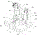
FIG. 1 is a front right upper axial view of the present invention.
Fig. 2 is a schematic view of the left front lower axial view structure of the present invention.
Fig. 3 is a schematic top view of the present invention.
Fig. 4 is a left side view of the present invention.
Fig. 5 is a schematic front view of the present invention.
In the drawings, the corresponding relationship between the component names and the reference numbers is as follows:
1. a base plate; 2. a fixed table; 201. a V-shaped table; 3. a rotating clamp pin shaft; 4. a support mechanism; 401. a guide rail; 5. a hold-down mechanism; 501. a screw; 502. adjusting a knob; 503. a guide bar; 504. a pressing frame; 505. a pinch roller; 506. a transverse plate; 6. a displacement mechanism; 601. a slide bar; 7. a jump detecting platform; 701. a base table; 702. checking a frame; 703. a connecting rod; 704. a buffer spring; 705. a limiting hole; 706. a limiting column; 707. and (6) checking the wheel.
Detailed Description
The embodiments of the present invention will be described in further detail with reference to the drawings and examples. The following examples are intended to illustrate the invention but are not intended to limit the scope of the invention.
In the description of the present invention, "a plurality" means two or more unless otherwise specified; the terms "upper", "lower", "left", "right", "inner", "outer", "front", "rear", "head", "tail", and the like, indicate orientations or positional relationships based on the orientations or positional relationships shown in the drawings, are only for convenience in describing and simplifying the description, and do not indicate or imply that the device or element referred to must have a particular orientation, be constructed in a particular orientation, and be operated, and thus, should not be construed as limiting the invention. Furthermore, the terms "first," "second," "third," and the like are used for descriptive purposes only and are not to be construed as indicating or implying relative importance.
In the description of the present invention, it is to be noted that, unless otherwise explicitly specified or limited, the terms "connected" and "connected" are to be interpreted broadly, e.g., as being fixed or detachable or integrally connected; can be mechanically or electrically connected; may be directly connected or indirectly connected through an intermediate. The specific meanings of the above terms in the present invention can be understood in specific cases to those skilled in the art.
Example (b):
as shown in figures 1 to 5:
the invention provides a simple and efficient rotary clamp runout checking fixture, which comprises a bottom plate 1; a fixed table 2 is fixedly installed at the middle part of the bottom plate 1 close to the rear part, the fixed table 2 comprises a V-shaped table 201, the left end and the right end of the top plane of the fixed table 2 are respectively and fixedly provided with the V-shaped table 201, and two ends of a pin shaft 3 of the rotary clamp are placed in notches of the V-shaped table 201; a rotary clamp pin shaft 3 is transversely arranged on the fixed table 2; a supporting mechanism 4 is vertically and upwardly fixedly installed on the bottom plate 1 at the rear side of the fixed table 2, the supporting mechanism 4 comprises a guide rail 401, and the left end and the right end of the front side wall of the supporting mechanism 4 are respectively and fixedly provided with a vertical guide rail 401; a pressing mechanism 5 is arranged on the side wall of the front end of the supporting mechanism 4; a displacement mechanism 6 is fixedly arranged at the edge of the front end of the top plane of the bottom plate 1; a jumping detection platform 7 is slidably mounted on the displacement mechanism 6, and the rear end of the jumping detection platform 7 is in contact with the rotary clamp pin shaft 3.
Wherein, the hold-down mechanism 5 comprises a screw 501, an adjusting knob 502, a guide rod 503, a hold-down frame 504, a hold-down wheel 505 and a horizontal plate 506, the left end of the hold-down mechanism 5 is vertically screwed downwards with the screw 501, the upper end of the screw 501 is fixedly provided with the adjusting knob 502, the right end of the hold-down mechanism 5 is sleeved on the vertical guide rod 503 through the horizontal plate 506, the lower end of the guide rod 503 is fixedly arranged on the bottom plate 1, the left end and the right end of the horizontal plate 506 are respectively connected on the guide rail 401 through sliding blocks, the bottoms of the left end and the right end of the horizontal plate 506 are respectively and symmetrically provided with the hold-down frame 504, the lower end of the hold-down frame 504 is fixedly provided with the longitudinal hold-down wheel 505, when the screw 501 is rotated, the hold-down frames 504 at the two ends can be synchronously controlled to move, so as to fix the pin shaft 3 of the rotary clamp through the, to facilitate the jump check.
Wherein, the displacement mechanism 6 comprises a slide bar 601, and the middle part of the displacement mechanism 6 is transversely connected with the slide bar 601.
Wherein, beat and examine platform 7 and include base frame 701, check frame 702, connecting rod 703, buffer spring 704, spacing hole 705, spacing post 706 and inspection wheel 707, beat and examine platform 7 and slide to cup joint on slide bar 601, the rear end that beats and examine platform 7 is fixed to be docked with base frame 701, the perpendicular grafting of upper end middle part that beats and examine platform 7 has connecting rod 703, the rear end fixed connection of connecting rod 703 has concave check frame 702, the rear end lateral wall middle part fixed mounting of check frame 702 has the inspection wheel 707 tangent with gyration anchor clamps round pin axle 3, cup joint buffer spring 704 on the connecting rod 703 of check frame 702 front side, can install the sensor of beating at the connecting rod 703 tail end, so that obtain accurate beat inspection data, and beat and examine platform 7 and can remove about, can be accurate carry out comprehensive inspection to gyration anchor clamps round pin axle 3.
The specific use mode and function of the embodiment are as follows:
in the using process, as the left end and the right end of the top plane of the fixed table 2 are respectively fixedly provided with the V-shaped table 201, the two ends of the pin shaft 3 of the rotary fixture are placed in the groove of the V-shaped table 201, the left end of the pressing mechanism 5 is vertically screwed downwards with the screw 501, the upper end of the screw 501 is fixedly provided with the adjusting knob 502, the right end of the pressing mechanism 5 is sleeved on the vertical guide rod 503 through the horizontal transverse plate 506, the lower end of the guide rod 503 is fixedly arranged on the bottom plate 1, the left end and the right end of the transverse plate 506 are respectively connected on the guide rail 401 through the sliding block in a sliding way, the bottoms of the left end and the right end of the transverse plate 506 are respectively and symmetrically provided with the pressing frames 504, the lower end of the pressing frames 504 is fixedly provided with the longitudinal pressing wheel 505, when the screw 501 is rotated, the pressing frames 504 at the two ends can be synchronously controlled to move, due to the special structure of the pressing wheel 505, the rotary fixture pin shaft 3 can be ensured to have rotation capacity, so as to facilitate jumping inspection, the jumping inspection table 7 is sleeved on the sliding rod 601 in a sliding mode, the rear end of the jumping inspection table 7 is fixedly connected with the bottom table 701 in a butt joint mode, the middle of the upper end of the jumping inspection table 7 is vertically inserted with the connecting rod 703 in a splicing mode, the rear end of the connecting rod 703 is fixedly connected with the concave inspection frame 702, the middle of the side wall of the rear end of the inspection frame 702 is fixedly provided with the inspection wheel 707 tangent to the rotary fixture pin shaft 3, the connecting rod 703 at the front side of the inspection frame 702 is sleeved with the buffer spring 704, a jumping sensor can be installed at the tail end of the connecting rod 703, so as to obtain accurate jumping inspection data, the jumping inspection table 7 can move left and.
The embodiments of the present invention have been presented for purposes of illustration and description, and are not intended to be exhaustive or limited to the invention in the form disclosed. Many modifications and variations will be apparent to those of ordinary skill in the art. The embodiment was chosen and described in order to best explain the principles of the invention and the practical application, and to enable others of ordinary skill in the art to understand the invention for various embodiments with various modifications as are suited to the particular use contemplated.
Claims (6)
1. The utility model provides a simple and easy high-efficient gyration anchor clamps are beated and are examined utensil which characterized in that: comprises a bottom plate (1); a fixed platform (2) is fixedly arranged at the middle part of the bottom plate (1) close to the rear part; a rotary clamp pin shaft (3) is transversely arranged on the fixed table (2); a supporting mechanism (4) is vertically and upwards fixedly arranged on the bottom plate (1) at the rear side of the fixed table (2); a pressing mechanism (5) is arranged on the side wall of the front end of the supporting mechanism (4); a displacement mechanism (6) is fixedly arranged at the edge of the front end of the top plane of the bottom plate (1); and a jumping detection platform (7) is arranged on the displacement mechanism (6) in a sliding manner, and the rear end of the jumping detection platform (7) is contacted with the rotary clamp pin shaft (3).
2. The simple and efficient rotary clamp runout testing fixture of claim 1, wherein: fixed station (2) include V type platform (201), fixed station (2) top planar left end and right-hand member respectively fixed mounting have V type platform (201), and the both ends of gyration anchor clamps round pin axle (3) are then placed in V type platform (201) notch.
3. The simple and efficient rotary clamp runout testing fixture of claim 1, wherein: the supporting mechanism (4) comprises a guide rail (401), and the left end and the right end of the front side wall of the supporting mechanism (4) are respectively and fixedly provided with a vertical guide rail (401).
4. The simple and efficient rotary clamp runout testing fixture of claim 1, wherein: hold-down mechanism (5) include screw rod (501), adjust knob (502), guide bar (503), compress tightly frame (504), pinch roller (505) and diaphragm (506), the left end of hold-down mechanism (5) has screw rod (501) perpendicularly to the spiro union downwards, and the upper end fixed mounting of its screw rod (501) has adjust knob (502), the right-hand member of hold-down mechanism (5) cup joints on vertically guide bar (503) through horizontally diaphragm (506), and the lower extreme fixed mounting of its guide bar (503) is on bottom plate (1), the left end and the right-hand member of diaphragm (506) are respectively through slider sliding connection on guide rail (401), the bottom of diaphragm (506) left end and right-hand member is respectively the symmetry install and is compressed tightly frame (504), the lower extreme fixed mounting who compresses tightly frame (504) has fore-and-aft pinch roller (505).
5. The simple and efficient rotary clamp runout testing fixture of claim 1, wherein: the displacement mechanism (6) comprises a sliding rod (601), and the middle part of the displacement mechanism (6) is transversely connected with the sliding rod (601).
6. The simple and efficient rotary clamp runout testing fixture of claim 1, wherein: the jumping detection table (7) comprises a bottom table (701), a detection frame (702), a connecting rod (703), a buffer spring (704), a limiting hole (705), a limiting column (706) and a detection wheel (707), the jumping detection table (7) is sleeved on a sliding rod (601) in a sliding mode, the rear end of the jumping detection table (7) is fixedly connected with the bottom table (701), the middle of the upper end of the jumping detection table (7) is vertically inserted with the connecting rod (703), the rear end of the connecting rod (703) is fixedly connected with a concave detection frame (702), the middle of the side wall of the rear end of the detection frame (702) is fixedly provided with the detection wheel (707) tangent to a rotary clamp pin shaft (3), and the connecting rod (703) on the front side of the detection frame (702) is sleeved with the buffer spring (704).
Priority Applications (1)
| Application Number | Priority Date | Filing Date | Title |
|---|---|---|---|
| CN201911233986.6A CN110823150A (en) | 2019-12-05 | 2019-12-05 | Simple and easy high-efficient gyration anchor clamps are beated and are examined utensil |
Applications Claiming Priority (1)
| Application Number | Priority Date | Filing Date | Title |
|---|---|---|---|
| CN201911233986.6A CN110823150A (en) | 2019-12-05 | 2019-12-05 | Simple and easy high-efficient gyration anchor clamps are beated and are examined utensil |
Publications (1)
| Publication Number | Publication Date |
|---|---|
| CN110823150A true CN110823150A (en) | 2020-02-21 |
Family
ID=69543959
Family Applications (1)
| Application Number | Title | Priority Date | Filing Date |
|---|---|---|---|
| CN201911233986.6A Withdrawn CN110823150A (en) | 2019-12-05 | 2019-12-05 | Simple and easy high-efficient gyration anchor clamps are beated and are examined utensil |
Country Status (1)
| Country | Link |
|---|---|
| CN (1) | CN110823150A (en) |
Cited By (1)
| Publication number | Priority date | Publication date | Assignee | Title |
|---|---|---|---|---|
| CN113624125A (en) * | 2021-08-19 | 2021-11-09 | 江苏科技大学 | Semi-intelligent eccentricity detection system based on motor operation |
-
2019
- 2019-12-05 CN CN201911233986.6A patent/CN110823150A/en not_active Withdrawn
Cited By (1)
| Publication number | Priority date | Publication date | Assignee | Title |
|---|---|---|---|---|
| CN113624125A (en) * | 2021-08-19 | 2021-11-09 | 江苏科技大学 | Semi-intelligent eccentricity detection system based on motor operation |
Similar Documents
| Publication | Publication Date | Title |
|---|---|---|
| JP3556663B2 (en) | Dimension inspection equipment for machine parts | |
| CN106052532B (en) | Track of lifter assembly checking tool and its detection method | |
| CN107036504B (en) | Wall thickness measuring device and measuring method | |
| CN110231009A (en) | A kind of wheel bolt hole location automatic detection device and method | |
| CN209399959U (en) | A kind of bearing mounting height automatic measuring instrument | |
| CN110823150A (en) | Simple and easy high-efficient gyration anchor clamps are beated and are examined utensil | |
| CN210741421U (en) | Simple and easy high-efficient gyration anchor clamps are beated and are examined utensil | |
| CN212458221U (en) | Circuit board bending degree detection device | |
| CN210242694U (en) | Detection tool and detection system for detecting circular runout | |
| CN210533303U (en) | Optical lens piece eccentric instrument | |
| US5317811A (en) | Apparatus and method for measuring surfaces and lenses | |
| CN111351440A (en) | Measuring device based on grating ruler | |
| CN114076560B (en) | Shaft hole detection device of gearbox shifting fork shaft | |
| CN214276723U (en) | Gear shaft straightness detection table | |
| CN109341478A (en) | A kind of turbo blade dimension measuring device and measurement method | |
| CN210089611U (en) | Flatness out-of-tolerance continuous measuring device | |
| CN210718990U (en) | Jig device for detecting adjustable flatness | |
| CN212179780U (en) | Miniature slider detects platform | |
| CN109443141B (en) | A kind of three-dimensional tester | |
| CN209387430U (en) | A kind of metal contraction percentage of area computing device | |
| CN108405359B (en) | Automatic detector for radial clearance of deep groove ball bearing | |
| CN215177669U (en) | Measuring tool for symmetry degree of caliper body of brake | |
| CN212274860U (en) | Assembly section difference detection equipment | |
| CN218238748U (en) | Measuring instrument | |
| CN209840992U (en) | A width dimension measurement tool for rotation axis |
Legal Events
| Date | Code | Title | Description |
|---|---|---|---|
| PB01 | Publication | ||
| PB01 | Publication | ||
| WW01 | Invention patent application withdrawn after publication | ||
| WW01 | Invention patent application withdrawn after publication |
Application publication date: 20200221 |