CN110822733A - Efficient solar water heater with voltage control function - Google Patents
Efficient solar water heater with voltage control function Download PDFInfo
- Publication number
- CN110822733A CN110822733A CN201911187354.0A CN201911187354A CN110822733A CN 110822733 A CN110822733 A CN 110822733A CN 201911187354 A CN201911187354 A CN 201911187354A CN 110822733 A CN110822733 A CN 110822733A
- Authority
- CN
- China
- Prior art keywords
- heat collecting
- water tank
- gear
- water heater
- sealing
- Prior art date
- Legal status (The legal status is an assumption and is not a legal conclusion. Google has not performed a legal analysis and makes no representation as to the accuracy of the status listed.)
- Withdrawn
Links
Images


Classifications
-
- F—MECHANICAL ENGINEERING; LIGHTING; HEATING; WEAPONS; BLASTING
- F24—HEATING; RANGES; VENTILATING
- F24S—SOLAR HEAT COLLECTORS; SOLAR HEAT SYSTEMS
- F24S10/00—Solar heat collectors using working fluids
- F24S10/70—Solar heat collectors using working fluids the working fluids being conveyed through tubular absorbing conduits
-
- F—MECHANICAL ENGINEERING; LIGHTING; HEATING; WEAPONS; BLASTING
- F24—HEATING; RANGES; VENTILATING
- F24S—SOLAR HEAT COLLECTORS; SOLAR HEAT SYSTEMS
- F24S40/00—Safety or protection arrangements of solar heat collectors; Preventing malfunction of solar heat collectors
- F24S40/20—Cleaning; Removing snow
-
- F—MECHANICAL ENGINEERING; LIGHTING; HEATING; WEAPONS; BLASTING
- F24—HEATING; RANGES; VENTILATING
- F24S—SOLAR HEAT COLLECTORS; SOLAR HEAT SYSTEMS
- F24S50/00—Arrangements for controlling solar heat collectors
-
- F—MECHANICAL ENGINEERING; LIGHTING; HEATING; WEAPONS; BLASTING
- F24—HEATING; RANGES; VENTILATING
- F24S—SOLAR HEAT COLLECTORS; SOLAR HEAT SYSTEMS
- F24S80/00—Details, accessories or component parts of solar heat collectors not provided for in groups F24S10/00-F24S70/00
-
- Y—GENERAL TAGGING OF NEW TECHNOLOGICAL DEVELOPMENTS; GENERAL TAGGING OF CROSS-SECTIONAL TECHNOLOGIES SPANNING OVER SEVERAL SECTIONS OF THE IPC; TECHNICAL SUBJECTS COVERED BY FORMER USPC CROSS-REFERENCE ART COLLECTIONS [XRACs] AND DIGESTS
- Y02—TECHNOLOGIES OR APPLICATIONS FOR MITIGATION OR ADAPTATION AGAINST CLIMATE CHANGE
- Y02E—REDUCTION OF GREENHOUSE GAS [GHG] EMISSIONS, RELATED TO ENERGY GENERATION, TRANSMISSION OR DISTRIBUTION
- Y02E10/00—Energy generation through renewable energy sources
- Y02E10/40—Solar thermal energy, e.g. solar towers
- Y02E10/44—Heat exchange systems
Abstract
The invention relates to a high-efficiency solar water heater with a pressure control function, which comprises a water tank, at least two heat collecting pipes, an adjusting mechanism and a cleaning mechanism, wherein the adjusting mechanism comprises a sealing cylinder, a lifting cylinder, a supporting sleeve, a spring, a supporting rod, a vent pipe and a power cylinder, the cleaning mechanism comprises a power component, a transmission component, a second pipeline, a first pipeline, at least two nozzles and at least two cleaning components, the cleaning components comprise a connecting rod, a cleaning strip, a first gear and two mounting bearings, the transmission component comprises a first connecting shaft, a second gear and a third gear, the power component comprises fan blades, a second connecting shaft and a fourth gear, in the high-efficiency solar water heater with the pressure control function, the pressure in the solar water heater can be adjusted through the adjusting mechanism, the probability of damage of the solar water heater is reduced, and the heat collecting pipes are cleaned through the cleaning mechanism, the heating efficiency of the heat collecting pipe is improved, and the heating efficiency of the solar water heater is improved.
Description
Technical Field
The invention relates to the field of solar equipment, in particular to a high-efficiency solar water heater with a pressure control function.
Background
The solar water heater is a heating device for converting solar energy into heat energy, and heats water from low temperature to high temperature so as to meet the requirement of hot water in life and production of people. The solar water heater is divided into a vacuum tube type solar water heater and a flat plate type solar water heater according to the structural form, mainly uses the vacuum tube type solar water heater as a main part, and occupies 95 percent of domestic market share. The vacuum tube type domestic solar water heater is composed of heat collecting tube, water storage tank and support, and can convert solar energy into heat energy, and mainly depends on the vacuum heat collecting tube, and the vacuum heat collecting tube can utilize the principle of that hot water floats upwards and cold water sinks to make water produce microcirculation to obtain the required hot water.
When the solar water heater in the prior art is used, if sunlight is too strong, water in the solar water heater is evaporated into steam due to overhigh temperature, so that the internal pressure of the solar water heater is overhigh, the sealing performance of the solar water heater is damaged, and moreover, after the solar water heater in the prior art is used for a long time, a large amount of dust can be accumulated on a heat collecting pipe of the solar water heater, the dust can shield the sunlight, and the heating efficiency of the solar water heater is reduced.
Disclosure of Invention
The technical problem to be solved by the invention is as follows: in order to overcome the defects of the prior art, the high-efficiency solar water heater with the pressure control function is provided.
The technical scheme adopted by the invention for solving the technical problems is as follows: a high-efficiency solar water heater with a pressure control function comprises a water tank and at least two heat collecting pipes, wherein the water tank is cylindrical, the axes of the heat collecting pipes are perpendicular to the axis of the water tank, the heat collecting pipes are parallel to each other, one end of each heat collecting pipe is communicated with the water tank, the high-efficiency solar water heater also comprises an adjusting mechanism and a cleaning mechanism, the adjusting mechanism is arranged on the water tank, and the cleaning mechanism is arranged on each heat collecting pipe;
the adjusting mechanism comprises a sealing barrel, a lifting barrel, a supporting sleeve, a spring, a supporting rod, a vent pipe and a power barrel, wherein the axis of the sealing barrel is perpendicular to and intersected with the axis of the water tank, the bottom end of the sealing barrel is fixedly connected with the top of the water tank, the bottom end of the sealing barrel is communicated with the inside of the water tank, the supporting sleeve, the supporting rod and the lifting barrel are all coaxially arranged with the sealing barrel, the supporting sleeve is fixedly connected with the top end of the sealing barrel, the supporting rod penetrates through the supporting sleeve, the supporting rod is slidably connected with the supporting sleeve, the top end of the lifting barrel is in a sealing state, the lifting barrel is arranged inside the sealing barrel, the lifting barrel is slidably and hermetically connected with the sealing barrel, the bottom end of the supporting rod is fixedly connected with the top end of the lifting barrel, the spring is sleeved on the supporting rod, and the supporting, the spring is in a compressed state, the top end of the supporting rod is provided with a limiting block, the axis of the power cylinder is parallel to the axis of the water tank, one end of the power cylinder is communicated with the inside of the sealing cylinder, the other end of the power cylinder is in a sealed state, the axis of the vent pipe is parallel to the axis of the power cylinder, the vent pipe is arranged on one side of the lifting cylinder, which is close to the power cylinder, the inner diameter of the vent pipe is equal to that of the power cylinder, and the length of the supporting rod is smaller than the height of the sealing cylinder;
the cleaning mechanism comprises a power component, a transmission component, a second pipeline, a first pipeline, at least two nozzles and at least two cleaning components, wherein the first pipeline is arranged on one side of the water tank, which is close to the heat collecting pipes, the number of the nozzles is equal to that of the heat collecting pipes, the nozzles are in one-to-one correspondence with the heat collecting pipes, the nozzles are arranged on the first pipeline and communicated with the first pipeline, the nozzles are arranged right opposite to the heat collecting pipes, the first pipeline is communicated with one end, which is far away from the sealing cylinder, of the power cylinder through the second pipeline, the power component is arranged inside the power cylinder, the transmission component is arranged at one end of the water tank, the number of the cleaning components is equal to that of the heat collecting pipes, the cleaning components are in one-to-one correspondence with the heat collecting pipes, the cleaning components are respectively arranged on the heat collecting pipes, and two adjacent cleaning components in, the power assembly is connected with the cleaning assembly through the transmission assembly.
Preferably, in order to improve the automation degree of the solar water heater, a central control box is arranged on the water tank, and a PLC is arranged inside the central control box.
As preferred, in order to clean the thermal-collecting tube, clean subassembly includes connecting rod, clean strip, first gear and two installation bearings, the inner circle of two installation bearings respectively with the both ends fixed connection of thermal-collecting tube, the connecting rod is parallel with the thermal-collecting tube, the both ends of connecting rod respectively with the outer lane fixed connection of two installation bearings, clean strip sets up the one side that is close to the thermal-collecting tube at the connecting rod, clean strip supports with the thermal-collecting tube and leans on, first gear is installed on the outer lane of an installation bearing who is close to the water tank, two adjacent first gear intermeshing in each first gear.
Preferably, in order to drive the cleaning assembly to operate, the transmission assembly comprises a first connecting shaft, a second gear and a third gear, the first connecting shaft is perpendicular to the axis of the water tank, two fixed bearings are arranged on the first connecting shaft, the first connecting shaft is connected with the water tank through the fixed bearings, one end of the first connecting shaft is fixedly connected with the second gear, the second gear is meshed with one of the first gears, and the other end of the first connecting shaft is fixedly connected with the third gear.
Preferably, for providing power for the cleaning assembly, the power assembly comprises fan blades, a second connecting shaft and a fourth gear, the second connecting shaft is coaxially arranged with the power cylinder, a connecting bearing is arranged on the second connecting shaft, the second connecting shaft is connected with one end, far away from the sealing cylinder, of the power cylinder through the connecting bearing, one end of the second connecting shaft is fixedly connected with the fourth gear, the fourth gear is meshed with the third gear, the fan blades are arranged inside one end, close to the sealing cylinder, of the power cylinder, and the other end of the second connecting shaft is fixedly connected with the fan blades.
Preferably, the cleaning strip is made of rubber to improve the cleaning effect of the cleaning strip.
Preferably, in order to improve the heating efficiency of the heat collecting tube, the color of the heat collecting tube is black.
Preferably, in order to improve the sealing performance between the support sleeve and the support rod, a sealing ring is arranged at one end of the support sleeve, and the support sleeve is connected with the support rod in a sealing manner through the sealing ring.
Preferably, in order to reduce the probability of dislocation between the vent pipe and the power cylinder, a limiting groove is formed in one side of the supporting rod, a limiting block is fixed on the inner wall of the supporting sleeve and matched with the limiting groove, the limiting block is arranged inside the limiting groove and is in sliding connection with the limiting groove.
Preferably, in order to prolong the service life of the water tank, the inner wall of the water tank is coated with an anticorrosive coating.
The invention has the advantages that in the high-efficiency solar water heater with the pressure control function, the pressure in the solar water heater can be adjusted through the adjusting mechanism, the probability of damage of the solar water heater is reduced, compared with the existing adjusting mechanism, the adjusting mechanism can provide power for the cleaning mechanism, the energy-saving performance of the solar water heater is improved, in addition, the heat collecting pipes can be cleaned through the cleaning mechanism, the heating efficiency of the heat collecting pipes is improved, the heating efficiency of the solar water heater is improved, compared with the existing cleaning mechanism, the cleaning mechanism simultaneously cleans the heat collecting pipes through air flow sprayed out by the nozzles and the cleaning strips, and the cleaning effect of the heat collecting pipes is improved.
Drawings
The invention is further illustrated with reference to the following figures and examples.
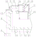
FIG. 1 is a schematic structural diagram of a high-efficiency solar water heater with a pressure control function according to the present invention;
FIG. 2 is a schematic diagram of the cleaning mechanism of the high efficiency solar water heater with pressure control function of the present invention;
FIG. 3 is a schematic structural diagram of an adjusting mechanism of the high-efficiency solar water heater with the pressure control function according to the present invention;
FIG. 4 is a schematic diagram of the cleaning assembly of the high efficiency solar water heater with pressure control function of the present invention;
in the figure: 1. the heat collecting pipe comprises a heat collecting pipe, 2 cleaning strips, 3 connecting rods, 4 mounting bearings, 5 first gears, 6 second gears, 7 first pipelines, 8 first connecting shafts, 9 power cylinders, 10 second pipelines, 11 sealing cylinders, 12 water tanks, 13 third gears, 14 fourth gears, 15 second connecting shafts, 16 fan blades, 17 supporting sleeves, 18 supporting rods, 19 springs, 20 lifting cylinders, 21 nozzles and 22 vent pipes.
Detailed Description
The present invention will now be described in further detail with reference to the accompanying drawings. These drawings are simplified schematic views illustrating only the basic structure of the present invention in a schematic manner, and thus show only the constitution related to the present invention.
As shown in fig. 1, a high-efficiency solar water heater with a pressure control function comprises a water tank 12 and at least two heat collecting tubes 1, wherein the water tank 12 is cylindrical, the axes of the heat collecting tubes 1 are perpendicular to the axis of the water tank 12, the heat collecting tubes 1 are parallel to each other, one end of each heat collecting tube 1 is communicated with the water tank 12, the high-efficiency solar water heater further comprises an adjusting mechanism and a cleaning mechanism, the adjusting mechanism is arranged on the water tank 12, and the cleaning mechanism is arranged on each heat collecting tube 1;
the pressure in the solar water heater can be adjusted through the adjusting mechanism, the probability of damage of the solar water heater is reduced, the heat collecting pipe 1 can be cleaned through the cleaning mechanism, the heating efficiency of the heat collecting pipe 1 is improved, and the heating efficiency of the solar water heater is improved;
as shown in fig. 2-3, the adjusting mechanism includes a sealing cylinder 11, a lifting cylinder 20, a supporting sleeve 17, a spring 19, a supporting rod 18, a vent pipe 22 and a power cylinder 9, an axis of the sealing cylinder 11 is perpendicular to and intersects with an axis of the water tank 12, a bottom end of the sealing cylinder 11 is fixedly connected with a top of the water tank 12, a bottom end of the sealing cylinder 11 is communicated with an inside of the water tank 12, the supporting sleeve 17, the supporting rod 18 and the lifting cylinder 20 are coaxially disposed with the sealing cylinder 11, the supporting sleeve 17 is fixedly connected with a top end of the sealing cylinder 11, the supporting rod 18 passes through the supporting sleeve 17, the supporting rod 18 is slidably connected with the supporting sleeve 17, a top end of the lifting cylinder 20 is in a sealing state, the lifting cylinder 20 is disposed inside the sealing cylinder 11, the lifting cylinder 20 is slidably and sealingly connected with the sealing cylinder 11, a bottom end of the supporting rod 18 is fixedly connected with a top end of the, the spring 19 is sleeved on the support rod 18, the support sleeve 17 is fixedly connected with the lifting cylinder 20 through the spring 19, the spring 19 is in a compressed state, the top end of the support rod 18 is provided with a limit block, the axis of the power cylinder 9 is parallel to the axis of the water tank 12, one end of the power cylinder 9 is communicated with the inside of the sealing cylinder 11, the other end of the power cylinder 9 is in a sealed state, the axis of the vent pipe 22 is parallel to the axis of the power cylinder 9, the vent pipe 22 is arranged on one side, close to the power cylinder 9, of the lifting cylinder 20, the inner diameter of the vent pipe 22 is equal to that of the power cylinder 9, and the length of the support rod 18 is smaller than the height of the sealing cylinder 11;
under the supporting action of the supporting sleeve 17, the stability of the lifting cylinder 20 is improved through the supporting rod 18, meanwhile, the stability of the lifting cylinder 20 is further improved through the limiting action of the sealing cylinder 11 on the lifting cylinder 20, when the water temperature in the solar water heater is too high, the water in the solar water heater is evaporated into steam, the pressure in the water tank 12 is increased, the lifting cylinder 20 is pushed by the steam to rise along the sealing cylinder 11, the vent pipe 22 is coincided with the power cylinder 9, the vent pipe 22 is communicated with the power cylinder 9, the steam enters the power cylinder 9 through the vent pipe 22, the pressure in the water tank 12 is reduced, the lifting cylinder 20 is driven by the spring 19 to fall along the sealing cylinder 11, the vent pipe 22 is staggered with the power cylinder 9, the water tank 12 is in a sealing state, the rising distance of the lifting cylinder 20 can be adjusted through the air pressure, the overlapping area between the vent pipe 22 and the power cylinder 9 can be controlled, the exhaust speed can be adjusted according to the air pressure in the water tank 12, so that the speed of adjusting the pressure in the water tank 12 is increased, and the probability of damage to the solar water heater is reduced;
as shown in fig. 2 and 4, the cleaning mechanism includes a power assembly, a transmission assembly, a second pipeline 10, a first pipeline 7, at least two nozzles 21 and at least two cleaning assemblies, the first pipeline 7 is disposed on one side of the water tank 12 close to the heat collecting pipes 1, the number of the nozzles 21 is equal to the number of the heat collecting pipes 1, the nozzles 21 are in one-to-one correspondence with the heat collecting pipes 1, the nozzles 21 are arranged on the first pipeline 7, the nozzles 21 are communicated with the first pipeline 7, the nozzles 21 are opposite to the heat collecting pipes 1, the first pipeline 7 is communicated with one end of the power cylinder 9 far away from the sealing cylinder 11 through the second pipeline 10, the power assembly is disposed inside the power cylinder 9, the transmission assembly is disposed on one end of the water tank 12, the number of the cleaning assemblies is equal to the number of the heat collecting pipes 1, the cleaning assemblies are in one-to-one correspondence with the heat collecting pipes 1, each cleaning component is arranged on each heat collecting pipe 1, two adjacent cleaning components in each cleaning component are connected with each other, and the power component is connected with the cleaning components through a transmission component;
when steam flows through the power cylinder 9, the power assembly is driven to operate by steam, power is provided by the power assembly, the cleaning assembly is driven to operate by the transmission assembly, then the heat collecting pipe 1 is cleaned by the cleaning assembly, the absorption efficiency of the heat collecting pipe 1 to sunlight is improved, the heating efficiency of the solar water heater is improved, then the steam inside the power cylinder 9 is conveyed to each nozzle 21 through the second pipeline 10 and the first pipeline 7, then the steam is sprayed onto the heat collecting pipe 1 through the nozzle 21, then the steam is condensed into water on the heat collecting pipe 1, then the cleaning effect of the heat collecting pipe 1 is improved through the water, and the absorption efficiency of the heat collecting pipe 1 to the sunlight is further improved.
Preferably, in order to improve the automation degree of the solar water heater, a central control box is arranged on the water tank 12, and a PLC is arranged inside the central control box;
the PLC programmable logic controller adopts a programmable memory for storing program therein, executing instructions facing users such as logic operation, sequence control, timing, counting and arithmetic operation, and controlling various types of machinery or production processes by digital or analog input/output, and is a computer specially used for industrial control, the hardware structure of the PLC programmable logic controller is basically the same as that of a microcomputer, and the PLC programmable logic controller is generally used for processing data and receiving and outputting instructions and is used for realizing central control, and the PLC programmable logic controller is used for controlling the operation of the smoking oven, so that the automation degree of the smoking oven is improved.
As shown in fig. 4, the cleaning assembly includes a connecting rod 3, a cleaning strip 2, a first gear 5 and two mounting bearings 4, inner rings of the two mounting bearings 4 are respectively fixedly connected with two ends of the heat collecting tube 1, the connecting rod 3 is parallel to the heat collecting tube 1, two ends of the connecting rod 3 are respectively fixedly connected with outer rings of the two mounting bearings 4, the cleaning strip 2 is arranged on one side of the connecting rod 3 close to the heat collecting tube 1, the cleaning strip 2 is abutted against the heat collecting tube 1, the first gear 5 is arranged on an outer ring of one mounting bearing 4 close to the water tank 12, and two adjacent first gears 5 are meshed with each other in each first gear 5.
As shown in fig. 2, the transmission assembly includes a first connecting shaft 8, a second gear 6 and a third gear 13, the first connecting shaft 8 is perpendicular to an axis of the water tank 12, two fixing bearings are arranged on the first connecting shaft 8, the first connecting shaft 8 is connected with the water tank 12 through the fixing bearings, one end of the first connecting shaft 8 is fixedly connected with the second gear 6, the second gear 6 is engaged with one of the first gears 5, and the other end of the first connecting shaft 8 is fixedly connected with the third gear 13.
As shown in fig. 3, the power assembly includes a fan blade 16, a second connecting shaft 15 and a fourth gear 14, the second connecting shaft 15 is coaxially disposed with the power cylinder 9, a connecting bearing is disposed on the second connecting shaft 15, the second connecting shaft 15 is connected with one end of the power cylinder 9 far away from the sealing cylinder 11 through the connecting bearing, one end of the second connecting shaft 15 is fixedly connected with the fourth gear 14, the fourth gear 14 is engaged with the third gear 13, the fan blade 16 is disposed inside one end of the power cylinder 9 close to the sealing cylinder 11, and the other end of the second connecting shaft 15 is fixedly connected with the fan blade 16;
when steam flows through power cylinder 9, rotate through steam drive flabellum 16, then rotate through second connecting axle 15 drive fourth gear 14, rotate through fourth gear 14 drive third gear 13, then under the transmission effect of first connecting axle 8, rotate through third gear 13 drive second gear 6, and then rotate through each first gear 5 of second gear 6 drive, rotate through first gear 5 drive installation bearing 4, then rotate around thermal-collecting tube 1 through connecting rod 3 drive cleaning strip 2, then clean thermal-collecting tube 1 through cleaning strip 2.
Preferably, in order to improve the cleaning effect of the cleaning strip 2, the cleaning strip 2 is made of rubber;
because the rubber is softer, the abrasion of the cleaning strips 2 to the heat collecting tube 1 is reduced, and the service life of the heat collecting tube 1 is prolonged.
Preferably, in order to improve the heating efficiency of the heat collecting tube 1, the color of the heat collecting tube 1 is black;
because black has a better sunlight absorption effect, the heating efficiency of the heat collecting tube 1 is improved.
Preferably, in order to improve the sealing performance between the support sleeve 17 and the support rod 18, a sealing ring is arranged at one end of the support sleeve 17, and the support sleeve 17 is connected with the support rod 18 in a sealing manner through the sealing ring;
the clearance between the support sleeve 17 and the support rod 18 is reduced through the sealing ring, and the probability of air leakage at the position of the support sleeve 17 is reduced.
Preferably, in order to reduce the probability of dislocation between the vent pipe 22 and the power cylinder 9, a limiting groove is formed in one side of the support rod 18, a limiting block is fixed on the inner wall of the support sleeve 17 and matched with the limiting groove, the limiting block is arranged inside the limiting groove and is connected with the limiting groove in a sliding manner;
through the mutual limiting action between the limiting groove and the limiting block, the probability that the supporting rod 18 rotates inside the supporting sleeve 17 is reduced, and the probability that the vent pipe 22 and the power cylinder 9 are staggered is reduced.
Preferably, in order to prolong the service life of the water tank 12, the inner wall of the water tank 12 is coated with an anti-corrosion coating;
the corrosion rate of the water tank 12 is slowed down through the anti-corrosion coating, and the service life of the water tank 12 is prolonged.
When the temperature of water in the solar water heater is too high, water in the solar water heater is evaporated into steam, the pressure in the water tank 12 is increased, the lifting cylinder 20 is pushed by the steam to ascend along the sealing cylinder 11, the vent pipe 22 is overlapped with the power cylinder 9, the vent pipe 22 is communicated with the power cylinder 9, the steam enters the power cylinder 9 through the vent pipe 22, the pressure in the water tank 12 is reduced, the probability of damage of the solar water heater is reduced, when the steam flows through the power cylinder 9, the power assembly is driven to operate by the steam, power is provided by the power assembly, the cleaning assembly is driven to operate by the transmission assembly, the heat collecting pipe 1 is cleaned by the cleaning assembly, the sunlight absorption efficiency of the heat collecting pipe 1 is improved, and the heating efficiency of the solar water heater is improved.
Compared with the prior art, in the high-efficiency solar water heater with the pressure control function, the pressure inside the solar water heater can be adjusted through the adjusting mechanism, the probability of damage of the solar water heater is reduced, compared with the existing adjusting mechanism, the adjusting mechanism can provide power for the cleaning mechanism, the energy-saving performance of the solar water heater is improved, furthermore, the heat collecting pipe 1 can be cleaned through the cleaning mechanism, the heating efficiency of the heat collecting pipe 1 is improved, the heating efficiency of the solar water heater is improved, compared with the existing cleaning mechanism, the cleaning mechanism can simultaneously clean the heat collecting pipe 1 through the air flow sprayed out by the nozzle 21 and the cleaning strip 2, and the cleaning effect of the heat collecting pipe 1 is improved.
In light of the foregoing description of the preferred embodiment of the present invention, many modifications and variations will be apparent to those skilled in the art without departing from the spirit and scope of the invention. The technical scope of the present invention is not limited to the content of the specification, and must be determined according to the scope of the claims.
Claims (10)
1. A high-efficiency solar water heater with a pressure control function comprises a water tank (12) and at least two heat collecting pipes (1), wherein the water tank (12) is cylindrical, the axes of the heat collecting pipes (1) are vertical to the axis of the water tank (12), the heat collecting pipes (1) are parallel to each other, one end of each heat collecting pipe (1) is communicated with the water tank (12), the high-efficiency solar water heater is characterized by further comprising an adjusting mechanism and a cleaning mechanism, the adjusting mechanism is arranged on the water tank (12), and the cleaning mechanism is arranged on each heat collecting pipe (1);
the adjusting mechanism comprises a sealing barrel (11), a lifting barrel (20), a supporting sleeve (17), a spring (19), a supporting rod (18), a vent pipe (22) and a power barrel (9), wherein the axis of the sealing barrel (11) is perpendicular to and intersected with the axis of a water tank (12), the bottom end of the sealing barrel (11) is fixedly connected with the top of the water tank (12), the bottom end of the sealing barrel (11) is communicated with the inside of the water tank (12), the supporting sleeve (17), the supporting rod (18) and the lifting barrel (20) are coaxially arranged with the sealing barrel (11), the supporting sleeve (17) is fixedly connected with the top end of the sealing barrel (11), the supporting rod (18) penetrates through the supporting sleeve (17), the supporting rod (18) is slidably connected with the supporting sleeve (17), the top end of the lifting barrel (20) is in a sealing state, and the lifting barrel (20) is arranged inside the sealing barrel (11), the lifting cylinder (20) is connected with the sealing cylinder (11) in a sliding and sealing manner, the bottom end of the supporting rod (18) is fixedly connected with the top end of the lifting cylinder (20), the spring (19) is sleeved on the supporting rod (18), the supporting sleeve (17) is fixedly connected with the lifting cylinder (20) through the spring (19), the spring (19) is in a compression state, the top end of the supporting rod (18) is provided with a limiting block, the axis of the power cylinder (9) is parallel to the axis of the water tank (12), one end of the power cylinder (9) is communicated with the inside of the sealing cylinder (11), the other end of the power cylinder (9) is in a sealing state, the axis of the vent pipe (22) is parallel to the axis of the power cylinder (9), the vent pipe (22) is arranged on one side, close to the power cylinder (9), of the lifting cylinder (20), and the inner diameter of the vent pipe (22) is equal to that of the power cylinder (9), the length of the supporting rod (18) is less than the height of the sealing cylinder (11);
the cleaning mechanism comprises a power component, a transmission component, a second pipeline (10), a first pipeline (7), at least two nozzles (21) and at least two cleaning components, wherein the first pipeline (7) is arranged on one side, close to the heat collecting pipes (1), of the water tank (12), the number of the nozzles (21) is equal to that of the heat collecting pipes (1), the nozzles (21) correspond to the heat collecting pipes (1) one to one, the nozzles (21) are arranged on the first pipeline (7), the nozzles (21) are communicated with the first pipeline (7), the nozzles (21) are arranged right opposite to the heat collecting pipes (1), the first pipeline (7) is communicated with one end, far away from the sealing barrel (11), of the power barrel (9) through the second pipeline (10), the power component is arranged inside the power barrel (9), the transmission component is arranged at one end of the water tank (12), the number of the cleaning components is equal to that of the heat collecting pipes (1), the cleaning components correspond to the heat collecting pipes (1) one by one, each cleaning component is arranged on each heat collecting pipe (1), two adjacent cleaning components in each cleaning component are connected with each other, and the power component is connected with the cleaning components through the transmission component.
2. The high-efficiency solar water heater with the pressure control function as claimed in claim 1, wherein a central control box is arranged on the water tank (12), and a PLC is arranged inside the central control box.
3. A high efficiency solar water heater with pressure control function as claimed in claim 1, the cleaning component comprises a connecting rod (3), a cleaning strip (2), a first gear (5) and two mounting bearings (4), the inner rings of the two mounting bearings (4) are respectively fixedly connected with the two ends of the heat collecting pipe (1), the connecting rod (3) is parallel to the heat collecting pipe (1), two ends of the connecting rod (3) are respectively and fixedly connected with the outer rings of the two mounting bearings (4), the cleaning strip (2) is arranged on one side of the connecting rod (3) close to the heat collecting pipe (1), the cleaning strip (2) is abutted to the heat collecting tube (1), the first gear (5) is installed on an outer ring of one installation bearing (4) close to the water tank (12), and two adjacent first gears (5) in each first gear (5) are meshed with each other.
4. The high-efficiency solar water heater with the pressure control function as claimed in claim 1, wherein the transmission assembly comprises a first connecting shaft (8), a second gear (6) and a third gear (13), the first connecting shaft (8) is perpendicular to the axis of the water tank (12), two fixed bearings are arranged on the first connecting shaft (8), the first connecting shaft (8) is connected with the water tank (12) through the fixed bearings, one end of the first connecting shaft (8) is fixedly connected with the second gear (6), the second gear (6) is meshed with one first gear (5), and the other end of the first connecting shaft (8) is fixedly connected with the third gear (13).
5. The efficient solar water heater with the pressure control function according to claim 1, wherein the power assembly comprises fan blades (16), a second connecting shaft (15) and a fourth gear (14), the second connecting shaft (15) and the power cylinder (9) are coaxially arranged, a connecting bearing is arranged on the second connecting shaft (15), the second connecting shaft (15) is connected with one end, far away from the sealing cylinder (11), of the power cylinder (9) through the connecting bearing, one end of the second connecting shaft (15) is fixedly connected with the fourth gear (14), the fourth gear (14) is meshed with the third gear (13), the fan blades (16) are arranged inside one end, close to the sealing cylinder (11), of the power cylinder (9), and the other end of the second connecting shaft (15) is fixedly connected with the fan blades (16).
6. The high-efficiency solar water heater with the pressure control function as claimed in claim 1, characterized in that the cleaning strip (2) is made of rubber.
7. The high-efficiency solar water heater with pressure control function as claimed in claim 1, characterized in that the color of the heat collecting tube (1) is black.
8. The high-efficiency solar water heater with the pressure control function as claimed in claim 1, wherein a sealing ring is arranged at one end of the support sleeve (17), and the support sleeve (17) is connected with the support rod (18) in a sealing way through the sealing ring.
9. The high-efficiency solar water heater with the pressure control function as claimed in claim 1, wherein a limiting groove is formed at one side of the supporting rod (18), a limiting block is fixed on the inner wall of the supporting sleeve (17), the limiting block is matched with the limiting groove, the limiting block is arranged inside the limiting groove, and the limiting block is connected with the limiting groove in a sliding manner.
10. A high efficiency solar water heater with pressure control function as claimed in claim 1 characterized by that the inner wall of the water tank (12) is coated with anti-corrosion coating.
Priority Applications (1)
| Application Number | Priority Date | Filing Date | Title |
|---|---|---|---|
| CN201911187354.0A CN110822733A (en) | 2019-11-28 | 2019-11-28 | Efficient solar water heater with voltage control function |
Applications Claiming Priority (1)
| Application Number | Priority Date | Filing Date | Title |
|---|---|---|---|
| CN201911187354.0A CN110822733A (en) | 2019-11-28 | 2019-11-28 | Efficient solar water heater with voltage control function |
Publications (1)
| Publication Number | Publication Date |
|---|---|
| CN110822733A true CN110822733A (en) | 2020-02-21 |
Family
ID=69541782
Family Applications (1)
| Application Number | Title | Priority Date | Filing Date |
|---|---|---|---|
| CN201911187354.0A Withdrawn CN110822733A (en) | 2019-11-28 | 2019-11-28 | Efficient solar water heater with voltage control function |
Country Status (1)
| Country | Link |
|---|---|
| CN (1) | CN110822733A (en) |
Cited By (3)
| Publication number | Priority date | Publication date | Assignee | Title |
|---|---|---|---|---|
| CN111322766A (en) * | 2020-03-23 | 2020-06-23 | 广州林电科技有限公司 | High-efficient solar heat collector with pressure release function |
| CN113983704A (en) * | 2021-11-18 | 2022-01-28 | 柴煜标 | Trough type light-gathering solar heat utilization water heating device |
| CN113983704B (en) * | 2021-11-18 | 2024-04-19 | 浙江星煜机电科技股份有限公司 | Trough type concentrating solar heat utilization water heating device |
-
2019
- 2019-11-28 CN CN201911187354.0A patent/CN110822733A/en not_active Withdrawn
Cited By (3)
| Publication number | Priority date | Publication date | Assignee | Title |
|---|---|---|---|---|
| CN111322766A (en) * | 2020-03-23 | 2020-06-23 | 广州林电科技有限公司 | High-efficient solar heat collector with pressure release function |
| CN113983704A (en) * | 2021-11-18 | 2022-01-28 | 柴煜标 | Trough type light-gathering solar heat utilization water heating device |
| CN113983704B (en) * | 2021-11-18 | 2024-04-19 | 浙江星煜机电科技股份有限公司 | Trough type concentrating solar heat utilization water heating device |
Similar Documents
| Publication | Publication Date | Title |
|---|---|---|
| CN110822735A (en) | Solar water heater with self-cleaning function | |
| CN102207340B (en) | Light-condensing type solar water heater | |
| CN205372898U (en) | Domestic quick air humidifier | |
| CN111981880B (en) | Combined heat pipe flue gas waste heat recovery device of thermal power plant | |
| CN206803112U (en) | A kind of energy-saving type boiler for the Desuperheating device that feeds water | |
| CN110822731A (en) | A solar water heating equipment that is used for heating efficiency of house to be high | |
| CN111380232B (en) | High-efficient solar heat collector convenient to it is clean | |
| CN110887246A (en) | Clean solar water heater with pressurization function | |
| CN110806020A (en) | Convenient clean type solar water heater of dismouting | |
| CN110822733A (en) | Efficient solar water heater with voltage control function | |
| CN111023586A (en) | Clean solar water heater with pressurization function | |
| CN110743285A (en) | Energy-saving fog gun machine with function of preventing frostbite | |
| CN110864393A (en) | Fresh air system with good warm-keeping effect and anti-blocking function | |
| CN110836541B (en) | Solar water heater with temperature control function | |
| AU2012283586A2 (en) | Rotary gas-gas heater with isolating air curtain structure in leaktight sealing system | |
| CN111322766B (en) | Solar heat collector with pressure relief function | |
| CN201496986U (en) | Energy-saving anti-clogging air heater | |
| CN2224334Y (en) | Automatic-rotating type ash-blowing device for tube-type heating stove | |
| CN201779685U (en) | Energy-saving anti-blockage steam air heater | |
| CN201348465Y (en) | Automatic cleaning system of condenser | |
| CN111322772A (en) | Solar water heater with heat collecting pipe cleaning function | |
| CN204372887U (en) | A kind of residual heat from boiler fume recycling system | |
| CN112502622A (en) | Drilling equipment for tunnel | |
| CN111023074A (en) | Boiler with high coal-fired efficiency and scale cleaning function | |
| CN111021276A (en) | Energy-saving reflector with cleaning function |
Legal Events
| Date | Code | Title | Description |
|---|---|---|---|
| PB01 | Publication | ||
| PB01 | Publication | ||
| SE01 | Entry into force of request for substantive examination | ||
| SE01 | Entry into force of request for substantive examination | ||
| CB02 | Change of applicant information |
Address after: 224007 No. 18, Xiangjiang Road, Yancheng City economic and Technological Development Zone, Jiangsu Applicant after: JIANGSU SUNNIC SOLAR ENERGY INDUSTRY Co.,Ltd. Address before: 224007 No. 18 Xiangjiang Road, Nanjing Economic and Technological Development Zone, Jiangsu Province Applicant before: JIANGSU SUNNIC SOLAR ENERGY INDUSTRY Co.,Ltd. |
|
| CB02 | Change of applicant information | ||
| WW01 | Invention patent application withdrawn after publication |
Application publication date: 20200221 |
|
| WW01 | Invention patent application withdrawn after publication |