CN110809553B - Automated storage and retrieval system - Google Patents
Automated storage and retrieval system Download PDFInfo
- Publication number
- CN110809553B CN110809553B CN201880039767.1A CN201880039767A CN110809553B CN 110809553 B CN110809553 B CN 110809553B CN 201880039767 A CN201880039767 A CN 201880039767A CN 110809553 B CN110809553 B CN 110809553B
- Authority
- CN
- China
- Prior art keywords
- container handling
- storage
- carrier
- container
- grid
- Prior art date
- Legal status (The legal status is an assumption and is not a legal conclusion. Google has not performed a legal analysis and makes no representation as to the accuracy of the status listed.)
- Active
Links
Images


Classifications
-
- G—PHYSICS
- G05—CONTROLLING; REGULATING
- G05B—CONTROL OR REGULATING SYSTEMS IN GENERAL; FUNCTIONAL ELEMENTS OF SUCH SYSTEMS; MONITORING OR TESTING ARRANGEMENTS FOR SUCH SYSTEMS OR ELEMENTS
- G05B19/00—Programme-control systems
- G05B19/02—Programme-control systems electric
- G05B19/418—Total factory control, i.e. centrally controlling a plurality of machines, e.g. direct or distributed numerical control [DNC], flexible manufacturing systems [FMS], integrated manufacturing systems [IMS], computer integrated manufacturing [CIM]
- G05B19/4189—Total factory control, i.e. centrally controlling a plurality of machines, e.g. direct or distributed numerical control [DNC], flexible manufacturing systems [FMS], integrated manufacturing systems [IMS], computer integrated manufacturing [CIM] characterised by the transport system
- G05B19/41895—Total factory control, i.e. centrally controlling a plurality of machines, e.g. direct or distributed numerical control [DNC], flexible manufacturing systems [FMS], integrated manufacturing systems [IMS], computer integrated manufacturing [CIM] characterised by the transport system using automatic guided vehicles [AGV]
-
- B—PERFORMING OPERATIONS; TRANSPORTING
- B65—CONVEYING; PACKING; STORING; HANDLING THIN OR FILAMENTARY MATERIAL
- B65G—TRANSPORT OR STORAGE DEVICES, e.g. CONVEYORS FOR LOADING OR TIPPING, SHOP CONVEYOR SYSTEMS OR PNEUMATIC TUBE CONVEYORS
- B65G1/00—Storing articles, individually or in orderly arrangement, in warehouses or magazines
- B65G1/02—Storage devices
- B65G1/04—Storage devices mechanical
- B65G1/0464—Storage devices mechanical with access from above
-
- B—PERFORMING OPERATIONS; TRANSPORTING
- B65—CONVEYING; PACKING; STORING; HANDLING THIN OR FILAMENTARY MATERIAL
- B65G—TRANSPORT OR STORAGE DEVICES, e.g. CONVEYORS FOR LOADING OR TIPPING, SHOP CONVEYOR SYSTEMS OR PNEUMATIC TUBE CONVEYORS
- B65G1/00—Storing articles, individually or in orderly arrangement, in warehouses or magazines
- B65G1/02—Storage devices
- B65G1/04—Storage devices mechanical
- B65G1/0478—Storage devices mechanical for matrix-arrangements
-
- B—PERFORMING OPERATIONS; TRANSPORTING
- B65—CONVEYING; PACKING; STORING; HANDLING THIN OR FILAMENTARY MATERIAL
- B65G—TRANSPORT OR STORAGE DEVICES, e.g. CONVEYORS FOR LOADING OR TIPPING, SHOP CONVEYOR SYSTEMS OR PNEUMATIC TUBE CONVEYORS
- B65G1/00—Storing articles, individually or in orderly arrangement, in warehouses or magazines
- B65G1/02—Storage devices
- B65G1/04—Storage devices mechanical
- B65G1/137—Storage devices mechanical with arrangements or automatic control means for selecting which articles are to be removed
- B65G1/1373—Storage devices mechanical with arrangements or automatic control means for selecting which articles are to be removed for fulfilling orders in warehouses
- B65G1/1375—Storage devices mechanical with arrangements or automatic control means for selecting which articles are to be removed for fulfilling orders in warehouses the orders being assembled on a commissioning stacker-crane or truck
-
- B—PERFORMING OPERATIONS; TRANSPORTING
- B66—HOISTING; LIFTING; HAULING
- B66F—HOISTING, LIFTING, HAULING OR PUSHING, NOT OTHERWISE PROVIDED FOR, e.g. DEVICES WHICH APPLY A LIFTING OR PUSHING FORCE DIRECTLY TO THE SURFACE OF A LOAD
- B66F9/00—Devices for lifting or lowering bulky or heavy goods for loading or unloading purposes
- B66F9/06—Devices for lifting or lowering bulky or heavy goods for loading or unloading purposes movable, with their loads, on wheels or the like, e.g. fork-lift trucks
- B66F9/063—Automatically guided
Abstract
The present invention relates to an automated storage and retrieval system comprising: a track system comprising a first set of parallel tracks arranged in a horizontal plane and extending in a first direction, and a second set of parallel tracks arranged in a horizontal plane and extending in a second direction orthogonal to the first direction, the first and second sets of tracks forming a grid pattern in the horizontal plane, the grid pattern comprising a plurality of adjacent grid cells, each grid cell comprising a grid opening defined by a pair of adjacent tracks of the first set of tracks and a pair of adjacent tracks of the second set of tracks; a plurality of stacks of storage containers arranged in storage columns located below the track system, wherein each storage column is located vertically below a grid opening; a plurality of container handling carriers for lifting and moving storage containers stacked in a stack, the container handling carriers configured to move laterally on a rail system above a storage column to access the storage containers via a grid opening, wherein each of the plurality of container handling carriers comprises: a wheel assembly for guiding the container handling vehicle along the rail system; wherein the container handling carrier has a footprint with a horizontal extension equal to or smaller than a horizontal extension of the grid cells. Each container handling carrier comprising: a ledge extending horizontally beyond the footprint of the container handling carrier and into an adjacent grid cell when the container handling carrier is positioned above the grid cell; and a recessed portion arranged to receive the protruding portion of the other container handling carrier when the other container handling carrier is operated on an adjacent grid cell. The invention also relates to a container handling carrier for such an automated storage and retrieval system and to a method of operating such an automated storage and retrieval system.
Description
Technical Field
The present invention relates to an automated storage and retrieval system.
In particular, the present invention relates to an automated storage and retrieval system comprising:
-a rail system comprising a first set of parallel rails arranged in a horizontal plane and extending in a first direction, and a second set of parallel rails arranged in a horizontal plane and extending in a second direction orthogonal to the first direction, the first and second sets of rails forming a grid pattern in the horizontal plane, the grid pattern comprising a plurality of adjacent grid cells, each grid cell comprising a grid opening defined by a pair of adjacent rails of the first set of rails and a pair of adjacent rails of the second set of rails;
-a stack of a plurality of storage containers arranged in storage columns located below the rail system, wherein each storage column is located vertically below a grid opening;
-a plurality of container handling carriers for lifting and moving storage containers stacked in a stack, the container handling carriers configured to move laterally on a rail system above a storage column to access the storage containers via a grid opening, wherein each of the plurality of container handling carriers comprises:
-a wheel assembly for guiding the container handling vehicle along the rail system;
wherein the container handling carrier has a footprint with a horizontal extent equal to or less than a horizontal extent of the grid cells.
The invention also relates to a container handling carrier for such an automated storage and retrieval system, the container handling carrier comprising: a lower portion including a wheel assembly for guiding the container handling vehicle along a horizontal track system of an automated storage and retrieval system; and a storage space centrally disposed within the lower portion for accommodating a storage container of the automated storage and retrieval system.
The invention also relates to a method of operating such an automated storage and retrieval system.
Background
An example of an automated storage and retrieval system of the type described above is shown in WO2016/120075a1, the contents of which are incorporated herein by reference. The disclosed container handling vehicle is dimensioned such that it has a footprint, i.e. a contact area with the rail system, the horizontal extension of which is equal to the horizontal extension of the grid cells. This allows the container handling vehicles to be operated simultaneously over adjacent grid cells, freeing more space for the container handling vehicles to travel on the track system than prior art systems.
In the prior art, such container handling carriers, i.e. container handling carriers whose horizontal extension of the footprint corresponds to the horizontal extension of a single grid cell, are sometimes referred to as "single cell" container handling carriers.
WO2015/193278a1 discloses another single unit container handling carrier, the contents of which are incorporated herein by reference.
The single unit design disclosed in WO2016/120075a1 and WO2015/193278a1 reduces the space required for container handling vehicles to travel on the track system, allowing more vehicles to operate on the track system without interfering with each other.
In some cases it may be beneficial for the horizontal extension of the container handling carrier to be larger than a single grid cell. For example, if the container handling carrier is operating in a battery replacement mode (indicating that it is moving to a battery replacement station to replace its onboard battery when the container handling carrier is nearing exhaustion), it may be advantageous to locate the battery bay or slot in a portion of the vehicle body protruding beyond the vehicle footprint in order to facilitate battery replacement.
If the horizontal extension of the footprint of the container handling carrier corresponds to the horizontal extension of the grid space, the protruding battery tray will protrude into the adjacent grid cell when the carrier is positioned above the grid cell. This will prevent other container handling vehicles from operating on adjacent grid cells, thereby limiting the available space for other container handling vehicles to operate on the track system.
In view of the above, it is desirable to provide an automated storage and retrieval system, a container handling carrier for use in such a system and a method of operating such a system that addresses or at least ameliorates the above-mentioned problems associated with operating container handling carriers on a track system.
Disclosure of Invention
According to one aspect of the invention, the system is characterised in that each container handling carrier comprises:
-a protruding portion extending horizontally beyond the footprint of the container handling carrier and into an adjacent grid cell when the container handling carrier is positioned above the grid cell; and
-a recessed portion arranged to receive a protruding portion of another container handling carrier when it is operated on an adjacent grid cell.
The recessed portion is a gap area adapted to provide clearance for and/or temporarily accommodate the protruding portion of another container handling carrier when the other container handling carrier is operated on an adjacent grid cell, thereby allowing two container handling carriers to be operated on adjacent grid cells or to pass each other without contact between the container handling carriers.
According to another aspect of the invention, the container handling carrier is characterized by comprising a protruding portion extending horizontally beyond the lower portion and a recessed portion arranged to receive the protruding portion of another container handling carrier when the other container handling carrier is operated on the track system.
Another aspect of the invention relates to a method of operating an automated storage and retrieval system in which a protruding portion of a first container handling carrier is received within a recessed portion of a second container handling carrier when the first and second container handling carriers are operated on adjacent grid cells.
Thus, when operating on a track system, the recessed portion of each container handling carrier is able to accommodate the protruding portion of other container handling carriers as they pass adjacent grid cells, thereby allowing the container handling carriers to travel along adjacent grid cell rows.
The shape of the recessed portion may be complementary to the shape of the protruding portion. However, the recessed portion may have a shape different from the protruding portion as long as the recessed portion is capable of accommodating the protruding portion of another carrier when the carrier passes through the adjacent grid cell.
The recessed portion may advantageously extend across the entire width or length of the container handling carrier in a direction orthogonal to the direction of extension of the protruding portion, thereby allowing two carriers to pass each other completely over adjacent grid cells. In other words, the recessed portion forming the gap region may extend from one side of the container handling carrier.
The protruding portion and the recessed portion may be arranged in an upper portion of the container handling carrier.
The wheel assembly may comprise a first set of wheels for engaging with the first set of tracks to guide movement of the container handling carrier in a first direction, and a second set of wheels for engaging with the second set of tracks to guide movement of the container handling carrier in a second direction.
The container handling carrier may comprise a container receiving storage space for receiving storage containers; and a lifting device arranged to transport the storage container vertically between a storage position in the stack and a transport position in the storage space. The lifting device may comprise a gripping device configured to releasably grip the storage container; and a lifting motor configured to raise and lower the clamping device with respect to the storage space.
The container receiving storage space may be centrally disposed within the container handling carrier lower portion.
The protruding portion may include at least one of: a rechargeable battery; a battery well for receiving a replaceable battery; and a sensor for determining the position of the vehicle on the track system or relative to other vehicles on the track system.
The wheel assembly may include wheels arranged around a periphery of the storage space.
In the following description, by way of example only, numerous specific details are set forth in order to provide a thorough understanding of the claimed system, vehicle, and method embodiments. One skilled in the relevant art will recognize, however, that the embodiments can be practiced without one or more of the specific details, or with other components, systems, etc. In other instances, well-known structures or operations are not shown or described in detail to avoid obscuring aspects of the disclosed embodiments.
Drawings
The accompanying drawings are included to provide a further understanding of the invention.
FIG. 1 is a first side view of an embodiment of an automated storage and retrieval system according to the present invention.
FIG. 2 is a second side view of the automated storage and retrieval system of FIG. 1, the second side view being orthogonal to the first side view.
Fig. 3 is a top view of the automated storage and retrieval system of fig. 1 and 2.
Fig. 4-7 are perspective views of a container handling carrier operating on a grid cell of the automated storage and retrieval system according to fig. 1.
Fig. 8 is a top view of a track system of the automated storage and retrieval system according to fig. 1.
Fig. 9 is a top view of an alternative track system of the automated storage and retrieval system according to the present invention.
Fig. 10 is a perspective view of a container handling carrier according to one embodiment of the invention with the top cover and side panels of the carrier removed.
Fig. 11 is a side view of the container handling carrier according to fig. 10.
Fig. 12 is a cross-sectional view of the container handling carrier according to fig. 10.
Fig. 13 is a perspective view schematically illustrating an alternative embodiment of a container handling carrier according to the present invention.
Figures 14A-14C show the charging and/or battery exchange station in perspective view and in side view along the X-direction and in side view along the Y-direction, respectively.
Fig. 15A to 17 show one possible battery replacement process.
Fig. 18 shows an example of a battery in a perspective view.
Fig. 19 shows a battery with the support rail fully inserted into the battery compartment.
In the drawings, the same reference numerals are used to designate the same components, elements or features unless explicitly stated or implicitly understood from the context.
Detailed Description
In the following, embodiments of the invention will be discussed in more detail, by way of example only, and with reference to the accompanying drawings. It should be understood, however, that the drawings are not intended to limit the invention to the subject matter described in the drawings.
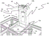
An embodiment of the storage structure of the automated storage and retrieval system 1 according to the present invention will now be discussed in more detail with reference to fig. 1 to 8.
The storage structure comprises a frame 2 on which frame 2a plurality of container handling carriers 3a, 3b operate.
The frame 2 comprises a plurality of upright members 4 and a plurality of horizontal members 5 supported by the upright members 4. The members 4, 5 may typically be made of metal, for example extruded aluminium profiles.
The frame 2 defines a three-dimensional storage grid comprising storage columns 7 arranged in rows, and storage containers 8 (also referred to as storage bins) stacked one on top of the other within the storage columns 7 to form a stack 9. Each storage container 8 may typically hold a plurality of product items (not shown), and the product items within the storage containers 8 may be the same, or may be different product types, depending on the application of the system 1. The frame 2 prevents the stack 9 of storage containers 8 from moving horizontally and guides the containers 8 to move vertically, but does not generally support the storage containers 8 when the storage containers 8 are stacked.
The horizontal member 5 comprises a rail or track system 10 (see fig. 1 and 3) arranged in a horizontal plane P above the storage column 7, on which track system 10 a plurality of container handling carriers 3 can be moved laterally above the storage column 7 to raise and lower storage containers 8 from the storage column 7 into the storage column 7 and also transport the storage containers 8 above the storage column 7.
The track system 10 comprises a first set of parallel rails or tracks 11 and a second set of parallel rails or tracks 12, the first set of parallel rails or tracks 11 being arranged to guide the container handling carriers 3 in a first direction X, the second set of parallel rails or tracks 12 being arranged perpendicular to the first set of tracks 11 to guide the container handling carriers 3 in a second direction Y perpendicular to the first direction X.
The rail system 10 forms a grid structure or grid pattern 13 in a horizontal plane P (see fig. 3). The grid pattern 13 comprises a plurality of rectangular and uniform grid positions or grid cells 14 (see fig. 8), wherein each grid cell 14 comprises a grid opening 15 defined by a pair of rails 11a, 11b of the first set of rails 11 and a pair of rails 12a, 12b of the second set of rails 12. In fig. 8, the grid cells 14 are represented by boxes with dashed borders and the grid openings 15 are represented by shaded areas.
Thus, the tracks 11a and 11b form track pairs defining parallel rows of grid cells extending in the X-direction, and the tracks 12a and 12b form track pairs defining parallel rows of grid cells extending in the Y-direction.
Width W of each grid cell 14cTypically in the range of 30 to 150 cm, length LcTypically in the range of 50 to 200 cm. Width W of each mesh opening 15oAnd length LoTypically respectively, than the width W of the grid cell 14cAnd length L c2 to 10 cm smaller.
In the X and Y directions, adjacent grid cells are arranged in contact with each other such that there is no space therebetween.
One embodiment of a container handling carrier 3 according to the invention will now be discussed in more detail with reference to fig. 10 to 12.
Each container handling carrier 3 comprises a vehicle body 17 and a wheel assembly 18, the wheel assembly 18 being arranged in a lower part or portion 17a (see fig. 12) of the vehicle body 17 to enable lateral movement of the container handling carriers 3, i.e. movement of the carriers 3 in the X and Y directions (see fig. 4).
The wheel assembly 18 comprises a first set of wheels 19 and a second set of wheels 20, the first set of wheels 19 being arranged to engage with a pair of rails 11a, 11b of the first set of rails 11, the second set of wheels 20 being arranged to engage with a pair of rails 12a, 12b of the second set of rails 12 (see fig. 10). At least one of the set of wheels 19, 20 may be raised and lowered so that the first set of wheels 19 and/or the second set of wheels 20 may engage the respective track set 11, 12 at any time.
Each set of wheels 19, 20 comprises four wheels 19a, 19b, 19c, 19 d; 20a, 20b, 20c, 20d, which are arranged along the side of the vehicle (see fig. 4 and 7). The wheels 19a and 19b are arranged in a first vertical plane and the wheels 19c and 19d are arranged in a second vertical plane parallel to and at a distance from the first vertical plane corresponding to the distance between the rails 11a and 11b (see fig. 8). The wheels 20a and 20b are arranged in a third vertical plane, orthogonal to the vertical plane in which the wheels 19a-19d are arranged, and the wheels 20c and 20d are arranged in a fourth vertical plane, parallel to the third vertical plane and arranged at a distance from the third vertical plane, which corresponds to the distance between the rails 12a and 12 b.
At least one wheel of each set of wheels 19, 20 is a motorized wheel for propelling the vehicle 3 along the track system 10. Advantageously, at least one motor wheel of each set of wheels comprises a hub motor, i.e. a motor coupled to or incorporated into the wheel hub and directly driving the wheel. An example of a container handling carrier with such a motor is disclosed in WO2016/120075a1, the contents of which are incorporated herein by reference.
Each container handling carrier 3 comprises a storage compartment or space 24, which storage compartment or space 24 is centrally arranged within the lower portion 7a of the car body 17 for receiving and holding a storage container 8 when transporting the storage container 8 through the track system 10. The storage space 24 is arranged within the body 17 and is accessible from below, i.e. from an opening (not shown) in the bottom of the container handling carrier 3.
Each container-handling carrier 3 further comprises lifting means 21 (see fig. 10) for vertically transporting the storage container 8, for example lifting the storage container 8 from the storage column 7 and bringing it into the storage space 24, and also for lowering the storage container 8 from the storage space 24 into the storage column 7. The lifting device 21 comprises a latch or catch device 22, which latch or catch device 22 is arranged to releasably engage with the storage container 8. The lifting device further comprises a lifting motor 23, which lifting motor 23 is used to lower and raise the gripping device 22 such that the position of the gripping device 22 relative to the body 17 can be adjusted in a third direction Z, which is orthogonal to the first direction X and the second direction Y (see also fig. 4).
Conventionally, and also for purposes of this application, Z ═ 1 identifies the uppermost layer of the storage grid, i.e., the layer directly below the track system 10, Z ═ 2 identifies the second layer below the track system 10, Z ═ 3 identifies the third layer, and so on. The container treatment carrier 3 can be said to travel in the layer Z ═ 0. Thus, each storage column may be identified by its X and Y coordinates, and each storage location in the storage grid may be identified by its X, Y and Z coordinates.
The lift motor 23 is arranged in a second upper or upper part 17b of the body 17 (see fig. 12), which upper part 17b is located above the lower part 17 a.
When a storage container 8 stored in the storage grid is to be accessed, one of the container handling carriers 3 is instructed to retrieve the target storage container 8 from its position in the storage grid from the target storage container 8 and to transport the target storage container 8 to an access station (not shown) where the target storage container 8 may be accessed from outside the storage grid or transferred out of the storage grid. The operation comprises moving the container handling carrier 3 to the grid cell 14 above the storage column 7 where the target storage container is located and retrieving the storage container from the storage column 7 using the lifting means 21 of the container handling carrier. This step comprises lifting the storage container from the storage column 7 through the grid openings 15 of the grid cells 14 and into the storage space 24 of the carrier 3 using the lifting means 21.
If the target storage container is located deep in the stack 9, i.e. one or more other storage containers are located above the target storage container, the operation further comprises temporarily moving the storage container located above before lifting the target storage container from the storage column 7. This step, sometimes referred to in the art as "digging," may be performed with the same container handling carrier that is subsequently used to transport the target storage container to the access station, or with one or more other cooperating container handling carriers. Alternatively, or in addition, the automated storage and retrieval system may have container handling carriers dedicated to the task of temporarily removing storage containers from the storage column. Once the target storage container has been removed from the storage column, the temporarily removed storage container may be relocated to the original storage column. However, the removed storage container may alternatively be relocated to other storage columns.
Once the target storage container has been brought into the storage space 24 of the container handling carrier 3, the carrier transports the storage container to the access station where it is unloaded. The access station may generally include a grid location at the periphery of the storage grid where the storage containers may be manually accessed or further transported using a suitable transport system.
When a storage container 8 is to be stored in the storage grid, one of the container handling carriers 3 is instructed to pick up a storage container from a pick-up station (not shown), which may also double as an access station, and transport the storage container to the grid cell above the storage column 7, where it is to be stored. After any storage containers located at or above the target position within the storage column stack have been removed, the container handling carrier 3 positions the storage containers in the desired position. The removed storage container may then be lowered back into storage column 7 or relocated to another storage column within the storage grid.
In order to monitor and control the automated storage and retrieval system so that desired storage containers can be transported to desired locations at desired times without container handling carriers 3 colliding with each other, the automated storage and retrieval system comprises a control system (not shown), which is typically computerized, and comprises a database for monitoring and controlling, for example, the position of individual storage containers 8 within the storage grid, the contents of each storage container 8, and the movement of container handling carriers 3.
The container handling carrier 3 typically communicates with the control system via wireless communication means, for example via WLAN employing IEEE 802.11(WiFi) standards and/or using mobile telecommunication technologies such as 4G or higher.
Each container handling carrier 3 comprises a battery 25, the battery 25 powering on-board equipment including the motor wheels, the lifting motor and the on-board control and communication system.
Each container handling carrier 3 has a footprint (footprint), i.e. a contact area with the rail system 10, the horizontal extension of which is equal to or less than the horizontal extension of the grid cells 14. In other words, when the carrier 3 is positioned above a grid cell 14, e.g. for lifting a storage container from a storage column 7 or lowering a container into a storage column 7, the footprint of the carrier 3 does not extend beyond the grid cell into an adjacent grid cell.
The wheels 19a-19d, 20a-20d are arranged around the periphery of the storage space 24 and the footprint 14 of the vehicle 3 is slightly larger than the storage space 24 just enough to accommodate the wheels 19a-19d, 20a-20 d. In this way the footprint 14 of the carrier 3 occupies the smallest possible amount of space in the X-Y plane. Since the storage space 24 is located between the pairs of wheels 19a-19d, 20a-20d on each side of the vehicle 3, the centre of gravity of the vehicle 3 will also be located within the footprint 14 when the storage bin is lifted into the storage space 24.
Furthermore, the vehicle 3 comprises substantially vertical side walls 26a-26d (see fig. 4, 6 and 7), which side walls 26a-26d are connected to the wheels 19a-19 d; 20a-20d are coplanar. Thus, the lower part of the container treatment carrier 3 is substantially rectangular parallelepiped.
However, the upper portion 17b of the carrier 3 has a ledge 27, which ledge 27 extends horizontally in the X-direction beyond the generally vertical side wall 26c (see, e.g., fig. 2 and 4). The protruding portion 27 accommodates the battery 25 of the carrier 3 (see fig. 7). Placing the batteries in this manner is advantageous because it allows easy access to the batteries for charging or battery exchange. In particular, if a battery replacement scheme is employed, in which case the projection 27 includes a battery compartment or slot 28 (see, e.g., fig. 12), the projecting feature of the projection 27 provides advantageous guidance for the battery 25 during a battery replacement operation.
The ledge 27 also allows for mounting of larger batteries in the carrier and is also beneficial when operating the carrier as a train of carriers, for example as disclosed in international patent application PCT/EP 2016/077300.
Alternatively or in addition, the ledge 27 may hold a look-down sensor that may be used to determine the position of the vehicle on the track system 10, such as the alignment of the vehicle with respect to the grid cells 14, or to determine the position of the vehicle with respect to other vehicles on the track system 10, such as when operating the vehicle as a train of vehicles.
When the carrier 3 is positioned above a grid cell 14, for example in order to access a container 8 in a storage column 7 positioned vertically below the grid cell 14, the protruding portion 27 will extend above an adjacent grid cell. In other words, the carrier 3 has a vertical protrusion occupying more than one grid cell, even if the contact area of the carrier 3 with the rail system 10 does not extend beyond the horizontal extent of one grid cell 14.
Typically this will prevent the second carrier from passing over an adjacent grid cell, i.e. a grid cell into which the protruding portion 27 of the first carrier extends. This can be a problem because it can reduce the overall capacity of the automated storage and retrieval system.
However, the container handling carrier 3 comprises a recessed portion 29, which recessed portion 29 is arranged at the upper portion 17b, opposite the protruding portion 27. In other words, the protruding portion 27 and the recessed portion 29 are arranged on opposite sides of the container handling carrier 3. The recessed portion 29 can accommodate the protruding portion 27 of the other carrier when the other carrier passes the adjacent grid cell. In particular, the shape of the recessed portion 29 is complementary to the shape of the protruding portion 27 and extends across the entire width of the container handling carrier 3 in the Y-direction, thereby allowing the carriers 3 to pass each other over adjacent grid cells.
This is illustrated in fig. 4-6, showing the first carrier 3a moved in to operate on a grid cell, while the second carrier 3b is located on an adjacent grid cell, while the protruding portion 27 of the first carrier 3a is received in the recessed portion 29 of the second carrier 3 b.
In the disclosed embodiment, the protruding portion 27 of each container handling carrier 3 extends in the X-direction and the recessed portion 29 extends across the entire width of the carrier 3 in the Y-direction. However, it will be appreciated that the protruding portion may alternatively extend in the Y-direction, while the recessed portion extends across the entire width of the carrier in the X-direction.
As schematically shown in the container handling carrier shown in fig. 13, each container handling carrier alternatively has two protruding portions 27 ', 27 "and two opposite complementary recessed portions 29', 29" extending in two orthogonal directions. This configuration will also allow two carriers to operate on adjacent grid cells without the projections 27' and 27 "interfering with the movement of the other carriers on the track system.
In the track system 10 shown in fig. 8, each horizontal member constituting the track includes two tracks. Thus, each horizontal member can accommodate two wheels in parallel. In such a rail system, the boundaries between adjacent grid cells extend along the centerline of the horizontal member, as shown in fig. 8.
Fig. 9 shows an alternative rail or track system 16, which is constructed of elongated members that each form a single track, i.e., a track configured to accommodate only one wheel. In such a rail system, the boundaries between adjacent grid cells extend midway between adjacent elongate members forming a single rail.
In fig. 9, the grid cells 14 include grid openings 15. On the left side (west) of the grid cell 14, there is an adjacent grid cell 14W comprising a grid opening 15W. Likewise, on the right side (east) of the grid cell 14, there is an adjacent grid cell 14E comprising a grid opening 15E. Further, below (south) the grid cell 14, there is an adjacent grid cell 14S including a grid opening 15S, and above (north) the grid cell 14, there is an adjacent grid cell 14N including a grid opening 15N.
In fig. 9, the footprint 30 of the container handling carrier is schematically shown. In this embodiment, the footprint 30 is defined by the horizontal extension of the vehicle wheels. As is evident from the figure, the horizontal extent of the footprint 30 is smaller than the horizontal extent of the grid cell.
In fig. 9, a footprint 30' of a container handling carrier according to an alternative embodiment is also schematically shown. In this case the lower part of the vehicle extends beyond the wheels and the horizontal extension of the footprint 30' is equal to the horizontal extension of the grid cells.
As previously described, the projection 27 may include a battery compartment or slot 28 for a rechargeable or replaceable battery 25. Such embodiments and associated battery replacement schemes will be discussed in more detail below with reference to fig. 14A through 19.
Examples of charging and/or battery exchange stations 40 (hereinafter referred to as charging stations) are shown in perspective view (fig. 14A) and in side view along the X-direction (fig. 14B) and in side view along the Y-direction (fig. 14C) in fig. 14A-14C.
The charging station 40 is mounted on a charging station base plate 41, the charging station base plate 41 being fixed (directly or indirectly) to adjacent rails 11a, 11b, 12a, 12b of the rail system above the grid posts at or near the periphery of the frame structure. The particular grid column containing charging stations 40 will be referred to hereinafter as a charging station unit.
The illustrated charging station 40 includes a vertical charging station post 42, the lower end 42a of the vertical charging station post 42 being secured to the base plate 41. A charging receptacle 45 is disposed at or near the upper end 42b of the pole 42, i.e., opposite the lower end 42a, and may be electrically connected to the power source 44 through a power transformer that converts the charging power to a desired power level.
The charging socket 45 is also configured to receive a charging plug 46 (see fig. 18) of the battery 25 mounted on each carrier 3, thereby allowing power to flow when the charging plug 46 is electrically coupled to the charging socket 45.
In a preferred construction, the charging socket 45 is resiliently attached to the charging station 42, for example, such that when no external force acts on the charging socket 45, the position of the charging socket 45 is fixed in an upper (unloaded) position, and when the charging socket carries the weight of the electrically connected battery 25, the position of the charging socket 45 is fixed in a lower (loaded) position.
Of course, the charging socket 45 and the charging plug 46 may be interchanged.
In general, any type of disconnectable electrical connection between charging station 40 and battery 25 is possible.
The automated storage and retrieval system described herein may include a plurality of such charging stations 40, with these charging stations 40 generally being arranged along the perimeter of the track system. However, alternatively or additionally, one or more charging stations 40 may be further placed in the track system and/or completely outside the track system. In the latter configuration, the charging station(s) 40 should be connected to the track system by additional tracks in order to allow the vehicles 3 to travel to their respective charging stations 40.
One possible battery replacement process will now be described with particular reference to fig. 15A-17.
The vehicle 3 has transferred its discharged or partially discharged main battery from the battery bay or slot in the battery cover 31 to a first charging station for charging, the vehicle 3 approaching a second charging station 40 containing the charged or partially charged main battery 25 (see fig. 15A and 16C).
To allow the vehicle to enter the charging station storage unit, the first set of wheels 19a-D should contact the underlying track system (see fig. 15A-15D), and the second set of wheels 20a-D closest to the charging station 30 should be high enough above the track system so as not to interfere with the track in the Y direction.
When the second set of wheels 20a and 20b has entered the charging station storage unit, and before reaching the horizontal position where the charging station 40 contacts the approaching carrier 3, the carrier 3 is lowered towards the track system. The carrier 3 is lowered to allow correct alignment with the main battery 25 during battery replacement, since the weight of the battery 25 forces the charging socket 45 to lower (load) position as described above. The lowering of the carrier 3 also increases the overall stability of the exchange process. A typical vertical displacement of the carrier 3 is 5-15mm, for example 10 mm.
Thus, the charging station 40 should be configured such that the height of the main battery 25 being charged relative to the track system is approximately equal to the corresponding height of the battery bay on the vehicle 3 when the vehicle 3 is in the lowered position.
In order to allow the vehicle 3 to move without the main battery 25, an auxiliary battery may be mounted, for example, in the same or similar manner as disclosed in patent publication WO 2015/104263 a1, the contents of which are incorporated herein by reference. Other solutions are also conceivable, for example using an external power supply, such as a live rail, manual interference, etc.
In an alternative embodiment, the charging station 40 or the carrier 3 or a combination of both contains a plurality of batteries, so that the carrier does not need to be moved between the charging stations 40 during battery replacement. WO2017/220627a1, the disclosure of which is incorporated herein by reference, discloses a multi-battery charging station suitable for use in the above-described storage system 1.
The charged batteries 25 available on the second charging station 40 are mounted on a battery support 43, in the example shown in figures 14A to 16D, the battery support 43 is in the form of two guide pins 43a, 43b extending laterally into the rail system from each side of the upper end 42b of the charging station post 42.
When the carrier 3 contacts the charging station 40, a release mechanism 50 (see fig. 17) is activated, allowing the battery cover 31 to tilt about the rotation axis.
The release mechanism 50 includes pivot arms 51 disposed on either side of the battery compartment opening into which the battery 25 is to be inserted.
Further, each protruding end of the guide pins 43a, 43b (constituting the battery support 43) shows a tapered portion 52 (see fig. 14A and 14C). When the pivot arm 51 and the guide pin 43 are in contact, the pivot arm contact member 51a of each pivot arm 51 is pushed toward the tapered portion 52, thereby forcing the pivot arm 51 to make a pivoting motion upward (see fig. 15A, 16D, and 17). This pivoting movement releases the safety lock 51b (see fig. 15A and 19), thereby allowing the battery cover 31 to tilt as described above.
The operation of the release mechanism 50 is shown in each of the sequence diagrams in fig. 15A to 15F and fig. 17. For greater clarity, an enlarged area view of the release mechanism 50 is added in fig. 15A-15C and 15F. These enlarged area views clearly show that the pivot arm begins to move when in contact with the tapered portion 52, thereby removing the safety latch 51b from the battery cover 27, and then the battery 25 enters.
When the guide pin 43 with the battery 25 attached has entered the battery compartment 27a certain distance (see fig. 15B and 15C), the guide pin 43 releases the battery locks 27B, 27C, which battery locks 27B, 27C allow further entry until the battery 25 is fully in its final position within the battery compartment.
In fig. 19, the battery lock 27b, 27c includes a battery lock activator 27b in the form of a wheel and one or more blocking teeth 27c extending from the inner wall of the battery cover into the battery compartment. When the tapered end 52 of the guide pins 43a, 43b contacts the battery lock activator 27b, the battery cover 27 tilts upward, displacing the one or more teeth 27c so that the battery 25 and guide pins 43a, 43b can continue to move deeper into the battery compartment.
In this final position, and before the carrier 3 is retracted, the battery 25 may be electrically connected to the charging station 40 and the drive motors of the wheels 19a-d, 20 a-d.
When the battery is in its final position within the battery bay and is in electrical contact with the corresponding electrical connector of the carrier 3, the battery bay tilts back to its initial position such that the teeth 27c physically lock or retain the battery 25 within the battery bay. For example, the teeth 27c may enter dedicated recesses 49a (see fig. 17) in support rails 49 arranged on both sides of the battery 25.
The battery locks 27b, 27c may be any physical barrier within the battery compartment. As an alternative to the teeth 27c described above, the battery lock may comprise one or more protruding wedges beyond which the battery 25 may pass in one direction, but not in the other. In this configuration, the wedge will act as a battery lock activator 27 b.
When the battery 25 is in its final position and successfully locked in the battery compartment by the battery locks 27b, 27c, the second set of wheels 20a-d of the vehicle 3 is lifted from the rail system (typically between 5-15 mm), thereby raising the total height of the vehicle 3. This operation causes the battery 25 to be released from the battery support 43, for example, from dedicated pockets or tracks in the first and second guide pins 43a, 43b (see fig. 14A).
Since now the battery locks 27b, 27c lock the battery 25 in the battery bay and the battery 25 has been lifted from the battery support 43, the carrier 3 is retracted from the charging station storage unit so that the battery 25 is electrically connected to the carrier 3.
In addition to allowing successful battery replacement, blocking the battery 25 in the battery compartment 27a has the following advantages: during operation, the battery 25 is not accidentally displaced within the battery cover 27.
When the control system has sent instructions to the carrier 3 to place its battery 28 into the charging station 40 for charging, the steps for transferring the battery 28 from the carrier 3 to the charging station 40 are substantially identical or similar to the reverse order and direction of the steps described above for transferring the battery 28 from the charging station 40 to the carrier 3.
Thus, the carrier 3 is first raised to allow the carrier to enter the charging station storage unit without the second set of wheels 20 interfering with the track 11 in the second direction (Y) and aligning the working battery 25 with the charging plug 45 of the charging station 40. As described above, the charging plug 45 is in the upper unloaded position in the exemplary configuration of fig. 14A-17.
During the approach of the carrier 3 to the charging station 40, the wedge-shaped ends 52 of the first and second guide pins 43a, 43b first bring about the tilting of the battery compartment by means of the release mechanism 51, and then activate the battery locks 27b, 27c, so that the battery covers tilt upwards, thereby removing the blocking tooth 27c from the corresponding recess 49a in the support rail 49.
By lowering the carrier 3 towards the track system, the support rails 49 of the battery 28 engage with the battery support 43. Thus, subsequent retraction of the carrier 3 will leave the battery in the desired charging position on the charging station 40.
To allow for larger batteries within the carrier 3, the battery cover and the alternative release mechanism 50 may both be arranged such that they protrude horizontally in the X direction beyond the generally vertical side walls 26c and 26 d. In this way the total capacity of each vehicle 3 in the system 1 can be increased significantly without the need to widen the tracks 11, 12.
The configuration with protruding release mechanism 50 has an additional advantage in the event that manual intervention is required to remove the battery from the battery compartment, for example due to general maintenance or accidental battery blockage, as it allows for easy manual unlocking of the battery. That is, the protruding arrangement allows sufficient manual force to be exerted on the release mechanism 50, which would be difficult if, for example, the release mechanism 50 were arranged deep in the battery cover 27.
The above-described protruding configuration is also advantageous to ensure early engagement in charging station 40.
An example of the battery 25 is shown in perspective view in fig. 18. One of the two support rails 49 is shown protruding from a side wall of the battery 25. And the same support rail protrudes from the opposite side wall. The purpose of the support rails 49 is to ensure both a stable support of the battery 25 on the battery support/guide pins 43 and an accurate introduction and removal of the battery 25 into and out of the battery compartment during replacement. Fig. 19 shows the battery 25 with the support rails 49 fully inserted into the battery compartment. In the particular configuration shown in fig. 19, the battery 25 is approximately one-half of the maximum allowable volume of the battery.
In the foregoing description, various aspects of an automated storage and retrieval system according to the present invention have been described with reference to illustrative embodiments. However, this description is not intended to be construed in a limiting sense. Various modifications and changes of the illustrative embodiments, as well as other embodiments of the system, which are apparent to persons skilled in the art to which the invention pertains are deemed to lie within the scope of the invention as defined by the appended claims.
Claims (15)
1. An automated storage and retrieval system (1), comprising:
-a rail system (10, 16) comprising a first set of parallel rails (11) arranged in a horizontal plane (P) and extending in a first direction (X), and a second set of parallel rails (12) arranged in the horizontal plane (P) and extending in a second direction (Y) orthogonal to the first direction (X), the first and second sets of rails (11, 12) forming a grid pattern (13) in the horizontal plane (P), the grid pattern comprising a plurality of adjacent grid cells (14), each grid cell comprising a grid opening (15) defined by a pair of adjacent rails (11a, 11b) of the first set of rails (11) and a pair of adjacent rails (12a, 12b) of the second set of rails (12);
-a plurality of stacks (9) of storage containers (8) arranged in storage columns (7) located below the track system (10, 16), wherein each storage column (7) is located vertically below one grid opening (15);
-first and second container handling carriers (3, 3a, 3b) for lifting and moving storage containers (8) stacked in the stack (9), the first and second container handling carriers (3, 3a, 3b) being configured to move laterally on the rail system (10) above the storage column (7) to access the storage containers (8) via the grid opening (15), wherein each of the first and second container handling carriers (3, 3a, 3b) comprises:
-a wheel assembly (18) for guiding the first and second container handling carriers (3, 3a, 3b) along the rail system (10, 16);
wherein each of the first and second container handling carriers (3, 3a, 3b) has a footprint (30, 30') with a horizontal extent equal to or smaller than a horizontal extent of the grid cell (14),
characterized in that each of said first and second container handling carriers (3, 3a, 3b) comprises:
-a protruding portion (27) extending horizontally beyond the footprint (30, 30') of the container handling carrier (3a) and extending into an adjacent grid cell when the container handling carrier (3a) is located above the grid cell (14); and
-a recessed portion (29) arranged to accommodate a protruding portion (27) of a further container handling carrier (3, 3a, 3b) when the further container handling carrier is operated on an adjacent grid cell,
wherein the recessed portion (29a) of the first container handling carrier (3a) is arranged to receive the protruding portion (27b) of the second container handling carrier (3b) to allow the first and second container handling carriers (3a, 3b) to pass each other on adjacent grid cells.
2. System (1) according to claim 1, characterized in that the shape of said concave portion (29) is complementary to the shape of said convex portion (27).
3. System (1) according to claim 1 or 2, wherein the recessed portion (29) extends across the entire width or length of the container handling carrier (3) in a direction orthogonal to the direction of extension of the protruding portion (27).
4. The system (1) according to claim 1 or 2, characterized in that said protruding portion (27) comprises at least one of: a rechargeable battery; a battery well (28) for receiving a replaceable battery (25); and a look-down sensor.
5. System (1) according to claim 1 or 2, characterized in that the protruding portion (27) and the recessed portion (29) are arranged in the upper part of the container treatment carrier (3).
6. The system (1) according to claim 1 or 2, wherein said wheel assembly (18) comprises: a first set of wheels (19) for engaging with the first set of tracks (11) to guide movement of the container handling carriers (3, 3a, 3b) in the first direction (X); and a second set of wheels (20) for engaging with the second set of tracks (12) to guide movement of the container handling carriers (3, 3a, 3b) in the second direction (Y).
7. The system (1) according to claim 1 or 2, wherein the container handling carrier (3) comprises:
-a container accommodating storage space (24) for accommodating a storage container (8);
-a lifting device (21) arranged to transport storage containers (8) vertically between a storage position in a stack (9) and a transport position in the container receiving storage space (24), the lifting device (21) comprising:
-a clamping device (22) configured to releasably clamp the storage container (8); and
-a lifting motor (23) configured to raise and lower the gripping device (22) with respect to the container receiving and storing space (24).
8. System (1) according to claim 7, characterized in that the container accommodation storage space (24) is arranged centrally in a lower part of the container handling carrier (3).
9. A method of operating an automated storage and retrieval system (1) according to any of claims 1 to 8, wherein the protruding portion (27) of the first container processing carrier (3a) is received within the recessed portion (29) of the second container processing carrier (3b) as the first and second container processing carriers (3a, 3b) operate on adjacent grid cells and pass each other.
10. A container handling carrier (3, 3a, 3b) for an automated storage and retrieval system (1), the container handling carrier (3, 3a, 3b) comprising a lower portion (17a) comprising: a wheel assembly (18) for guiding the container handling carriers (3, 3a, 3b) along a horizontal rail system (10, 16) of the automated storage and retrieval system (1); and a storage space (24) arranged centrally within said lower portion (17a) for accommodating a storage container (8) of said automated storage and retrieval system (1), characterized in that said container handling carrier (3a) comprises: a projecting portion (27, 27', 27 ") extending horizontally beyond said lower portion (17 a); and a recessed portion (29, 29 ', 29 "), the recessed portion (29, 29 ', 29") being arranged to provide clearance for and/or temporarily accommodate a body of a protruding portion (27, 27 ', 27 ") corresponding to another container handling carrier (3b) when the other container handling carrier is operated on the track system (10, 16), thereby allowing the container handling carriers (3, 3a, 3b) having the protruding portion (27, 27 ', 27") and the recessed portion (29, 29 ', 29 ") to pass each other on adjacent grid cells.
11. A container handling carrier (3, 3a, 3b) according to claim 10, wherein the protruding portion (27, 27 ', 27 ") and the recessed portion (29, 29', 29") are arranged at an upper portion (17b) above the lower portion (17a) of the container handling carrier (3, 3a, 3 b).
12. A container handling carrier (3, 3a, 3b) according to claim 10 or 11, wherein the shape of the recessed portion (29, 29 ', 29 ") is complementary to the shape of the protruding portion (27, 27', 27").
13. A container handling carrier (3, 3a, 3b) according to claim 10 or 11, wherein the protruding portion (27, 27 ', 27 ") and the recessed portion (29, 29', 29") are arranged at opposite sides of the container handling carrier (3, 3a, 3 b).
14. A container handling carrier (3, 3a, 3b) according to claim 10 or 11, wherein the protruding portion (27, 27', 27 ") comprises at least one of: a rechargeable battery (25); a battery well (28) for receiving a replaceable battery (25); and a sensor for determining the position of a vehicle on the track system (10, 16) or relative to other vehicles on the track system (10, 16).
15. A container handling carrier (3, 3a, 3b) according to claim 10 or 11, wherein the wheel assembly (18) comprises wheels (19a-19d, 20a-20d) arranged around the periphery of the storage space (24).
Applications Claiming Priority (5)
| Application Number | Priority Date | Filing Date | Title |
|---|---|---|---|
| NO20170810A NO344463B1 (en) | 2017-05-16 | 2017-05-16 | Automated storage and retrieval system and method of operating same |
| NO20170810 | 2017-05-16 | ||
| NO20180586A NO20180586A1 (en) | 2018-04-25 | 2018-04-25 | Charging system for container handling vehicles and method of charging a power supply |
| NO20180586 | 2018-04-25 | ||
| PCT/EP2018/062578 WO2018210851A1 (en) | 2017-05-16 | 2018-05-15 | Automated storage and retrieval system |
Publications (2)
| Publication Number | Publication Date |
|---|---|
| CN110809553A CN110809553A (en) | 2020-02-18 |
| CN110809553B true CN110809553B (en) | 2021-10-15 |
Family
ID=62167350
Family Applications (1)
| Application Number | Title | Priority Date | Filing Date |
|---|---|---|---|
| CN201880039767.1A Active CN110809553B (en) | 2017-05-16 | 2018-05-15 | Automated storage and retrieval system |
Country Status (6)
| Country | Link |
|---|---|
| US (2) | US11360465B2 (en) |
| EP (1) | EP3634885B1 (en) |
| JP (2) | JP7049369B2 (en) |
| CN (1) | CN110809553B (en) |
| CA (1) | CA3063294A1 (en) |
| WO (1) | WO2018210851A1 (en) |
Families Citing this family (17)
| Publication number | Priority date | Publication date | Assignee | Title |
|---|---|---|---|---|
| US11858738B2 (en) * | 2013-08-09 | 2024-01-02 | Ocado Innovation Limited | Apparatus for retrieving units from a storage system |
| NO346327B1 (en) | 2017-05-16 | 2022-06-07 | Autostore Tech As | Automated storage and retrieval system |
| CA3063294A1 (en) * | 2017-05-16 | 2018-11-22 | Autostore Technology AS | Automated storage and retrieval system |
| NO20180586A1 (en) * | 2018-04-25 | 2019-10-28 | Autostore Tech As | Charging system for container handling vehicles and method of charging a power supply |
| NO344464B1 (en) * | 2017-10-19 | 2019-12-23 | Autostore Tech As | Vehicle for an automated storage and retrieval system and method of operating an automated storage and retrieval system |
| US11479407B2 (en) | 2018-01-09 | 2022-10-25 | Autostore Technology AS | Displacement mechanism for a remotely operated vehicle |
| NO20190567A1 (en) * | 2019-05-03 | 2020-11-04 | Autostore Tech As | Storage system |
| USD934324S1 (en) * | 2019-06-17 | 2021-10-26 | Autostore Technology AS | Autonomous transport robot |
| CN110255038A (en) * | 2019-07-15 | 2019-09-20 | 南京翌星自动化系统有限公司 | A kind of automatic reverse haulage equipment |
| CN110239871A (en) * | 2019-07-15 | 2019-09-17 | 南京翌星自动化系统有限公司 | A kind of logistics carrying storage system |
| NO345918B1 (en) * | 2019-09-16 | 2021-10-18 | Autostore Tech As | Automated storage and retrieval system using an automated loader and methods of replacing power supplies |
| DE102020203221A1 (en) | 2020-03-12 | 2021-09-16 | Gebhardt Fördertechnik GmbH | Vehicle for a storage system and charging station for the vehicle |
| NO346304B1 (en) * | 2020-06-25 | 2022-05-30 | Autostore Tech As | System and method of operating an automated storage and retrieval system |
| NO346543B1 (en) * | 2021-03-09 | 2022-09-26 | Autostore Tech As | A storage system featuring covers arrangeable in storage columns |
| NO20211496A1 (en) * | 2021-12-13 | 2023-06-14 | Autostore Tech As | Method for delivering goods to a customer utilizing optical character recognition |
| US11790946B2 (en) * | 2022-02-04 | 2023-10-17 | Seagate Technology Llc | Magnetically repositionable cassettes within a data storage drive |
| GB2619064A (en) * | 2022-05-26 | 2023-11-29 | Ocado Innovation Ltd | A combined power and data unit for a storage and retreival system, and related devices |
Citations (2)
| Publication number | Priority date | Publication date | Assignee | Title |
|---|---|---|---|---|
| US4088232A (en) * | 1974-04-01 | 1978-05-09 | Clark Equipment Co. | Apparatus with storage cells disposed adjacent vertical shafts having covers and a lift means movable thereabove |
| CN105899398A (en) * | 2014-01-08 | 2016-08-24 | 杰克布海特兰德物流有限公司 | Robot for transporting underlying bins with interchangeable main power source |
Family Cites Families (19)
| Publication number | Priority date | Publication date | Assignee | Title |
|---|---|---|---|---|
| SE375505B (en) | 1969-03-10 | 1975-04-21 | T J R Bright | |
| EP0857152B2 (en) | 1995-10-27 | 2004-03-17 | Westfalia WST Systemtechnik GmbH & Co. KG | Method and device for extracting rolling pallets in compact storage technology, and rolling pallet therefor |
| US8687315B2 (en) | 2011-05-11 | 2014-04-01 | International Business Machines Corporation | Data storage system using a media mobility unit (MMU), the MMU, and methods of use thereof |
| JP5830282B2 (en) | 2011-06-30 | 2015-12-09 | 株式会社岡村製作所 | Article conveying device |
| NL2007566C2 (en) | 2011-10-11 | 2013-04-15 | Lely Patent Nv | Vehicle system. |
| NO335839B1 (en) * | 2012-12-10 | 2015-03-02 | Jakob Hatteland Logistics As | Robot for transporting storage containers |
| US9785911B2 (en) | 2013-07-25 | 2017-10-10 | I AM Robotics, LLC | System and method for piece-picking or put-away with a mobile manipulation robot |
| GB201404870D0 (en) * | 2014-03-18 | 2014-04-30 | Ocado Ltd | Robotic service device and handling method |
| GB201314313D0 (en) * | 2013-08-09 | 2013-09-25 | Ocado Ltd | Apparatus for retrieving units from a storage system |
| NO337544B1 (en) | 2014-06-19 | 2016-05-02 | Jakob Hatteland Logistics As | Remote controlled vehicle assembly to pick up storage containers from a storage system |
| DK3050824T3 (en) | 2015-01-28 | 2019-11-04 | Autostore Tech As | ROBOT FOR TRANSPORTING STORAGE CONTAINERS |
| DK3374292T3 (en) * | 2015-11-11 | 2023-11-13 | Ocado Innovation Ltd | Robotic gripping systems and devices |
| GB201521488D0 (en) * | 2015-12-06 | 2016-01-20 | Ocado Innovation Ltd | Sequencing systems and methods |
| NO20160075A1 (en) | 2016-01-14 | 2017-04-03 | Autostore Tech As | Method for retrieving items from a storage system and storage system for storing and retrieving bins |
| NO20160118A1 (en) * | 2016-01-26 | 2017-07-27 | Autostore Tech As | Remotely operated vehicle |
| GB201603520D0 (en) * | 2016-02-29 | 2016-04-13 | Ocado Innovation Ltd | Robotic service device and handling method |
| US10497594B2 (en) * | 2016-03-03 | 2019-12-03 | Murata Machinery, Ltd. | Conveyance system |
| NO344308B1 (en) | 2016-06-21 | 2019-10-28 | Autostore Tech As | Storage system comprising a charging station assembly and method of replacing the power source of a remotely operated vehicle |
| CA3063294A1 (en) * | 2017-05-16 | 2018-11-22 | Autostore Technology AS | Automated storage and retrieval system |
-
2018
- 2018-05-15 CA CA3063294A patent/CA3063294A1/en active Pending
- 2018-05-15 WO PCT/EP2018/062578 patent/WO2018210851A1/en unknown
- 2018-05-15 JP JP2019563433A patent/JP7049369B2/en active Active
- 2018-05-15 CN CN201880039767.1A patent/CN110809553B/en active Active
- 2018-05-15 US US16/614,121 patent/US11360465B2/en active Active
- 2018-05-15 EP EP18724873.7A patent/EP3634885B1/en active Active
-
2022
- 2022-03-25 JP JP2022049402A patent/JP2022075973A/en active Pending
- 2022-05-03 US US17/661,844 patent/US11846935B2/en active Active
Patent Citations (2)
| Publication number | Priority date | Publication date | Assignee | Title |
|---|---|---|---|---|
| US4088232A (en) * | 1974-04-01 | 1978-05-09 | Clark Equipment Co. | Apparatus with storage cells disposed adjacent vertical shafts having covers and a lift means movable thereabove |
| CN105899398A (en) * | 2014-01-08 | 2016-08-24 | 杰克布海特兰德物流有限公司 | Robot for transporting underlying bins with interchangeable main power source |
Also Published As
| Publication number | Publication date |
|---|---|
| JP2020520329A (en) | 2020-07-09 |
| EP3634885B1 (en) | 2024-01-24 |
| JP2022075973A (en) | 2022-05-18 |
| JP7049369B2 (en) | 2022-04-06 |
| EP3634885A1 (en) | 2020-04-15 |
| CA3063294A1 (en) | 2018-11-22 |
| CN110809553A (en) | 2020-02-18 |
| US20210155407A1 (en) | 2021-05-27 |
| US11846935B2 (en) | 2023-12-19 |
| US20220260982A1 (en) | 2022-08-18 |
| US11360465B2 (en) | 2022-06-14 |
| WO2018210851A1 (en) | 2018-11-22 |
Similar Documents
| Publication | Publication Date | Title |
|---|---|---|
| CN110809553B (en) | Automated storage and retrieval system | |
| CN112041246B (en) | Automated storage and retrieval system having a charging station for charging a replaceable power source of a container handling vehicle | |
| CN110770147A (en) | Automated storage and retrieval system | |
| EP4234316A1 (en) | Automated storage and retrieval system using an automated loader and methods of replacing power supplies | |
| US20240126249A1 (en) | Automated storage and retrieval system | |
| NO344463B1 (en) | Automated storage and retrieval system and method of operating same |
Legal Events
| Date | Code | Title | Description |
|---|---|---|---|
| PB01 | Publication | ||
| PB01 | Publication | ||
| SE01 | Entry into force of request for substantive examination | ||
| REG | Reference to a national code |
Ref country code: HK Ref legal event code: DE Ref document number: 40021302 Country of ref document: HK |
|
| GR01 | Patent grant | ||
| GR01 | Patent grant |