CN110773945A - Welding fixture for manufacturing oil cylinder - Google Patents
Welding fixture for manufacturing oil cylinder Download PDFInfo
- Publication number
- CN110773945A CN110773945A CN201911251708.3A CN201911251708A CN110773945A CN 110773945 A CN110773945 A CN 110773945A CN 201911251708 A CN201911251708 A CN 201911251708A CN 110773945 A CN110773945 A CN 110773945A
- Authority
- CN
- China
- Prior art keywords
- sets
- wall
- pin rod
- groups
- plate
- Prior art date
- Legal status (The legal status is an assumption and is not a legal conclusion. Google has not performed a legal analysis and makes no representation as to the accuracy of the status listed.)
- Withdrawn
Links
Images


Classifications
-
- B—PERFORMING OPERATIONS; TRANSPORTING
- B23—MACHINE TOOLS; METAL-WORKING NOT OTHERWISE PROVIDED FOR
- B23K—SOLDERING OR UNSOLDERING; WELDING; CLADDING OR PLATING BY SOLDERING OR WELDING; CUTTING BY APPLYING HEAT LOCALLY, e.g. FLAME CUTTING; WORKING BY LASER BEAM
- B23K37/00—Auxiliary devices or processes, not specially adapted to a procedure covered by only one of the preceding main groups
- B23K37/04—Auxiliary devices or processes, not specially adapted to a procedure covered by only one of the preceding main groups for holding or positioning work
- B23K37/047—Auxiliary devices or processes, not specially adapted to a procedure covered by only one of the preceding main groups for holding or positioning work moving work to adjust its position between soldering, welding or cutting steps
Abstract
The invention discloses a welding fixture for manufacturing an oil cylinder, which comprises a support, a rotating device, a limiting device and clamping pieces, wherein the support comprises a bottom plate, a hydraulic cylinder and a movable plate, the hydraulic cylinder is fixed on the top wall of the bottom plate, a piston rod of the hydraulic cylinder is connected with one side of the movable plate, a plurality of groups of idler wheels are installed on the bottom wall of the movable plate, two groups of baffles are welded on the top wall of the movable plate, the top ends of the two groups of baffles are connected with a top plate, the rotating device, the limiting device and the clamping pieces are fixed on the top wall of the top plate, the two groups of clamping pieces are arranged, the rotating device and the limiting device are located between the two groups of clamping pieces, the rotating device comprises a speed regulating motor, a universal ball and a. The welding fixture for manufacturing the oil cylinder can fix oil cylinders of different types and is beneficial to welding different parts of the oil cylinder.
Description
Technical Field
The invention belongs to the technical field of oil cylinder machining, and particularly relates to a welding clamp for manufacturing an oil cylinder.
Background
The oil cylinder is a hydraulic actuator which converts hydraulic energy into mechanical energy and makes linear reciprocating motion (or swinging motion). The reciprocating motion device has simple structure and reliable work, can avoid a speed reducer when the reciprocating motion is realized, has no transmission clearance, and moves stably, thereby being widely applied to hydraulic systems of various machines. The hydro-cylinder need utilize anchor clamps to fix it at the in-process of processing, then welds it, and general anchor clamps are fixed the back with the hydro-cylinder, if need weld the different positions of hydro-cylinder, need artifical manual moving the hydro-cylinder, not only waste time and energy, are unfavorable for welding the different positions of hydro-cylinder moreover.
Therefore, in order to meet the current situation, the welding clamp for manufacturing the oil cylinder needs to be designed and produced urgently so as to meet the requirement of practical use.
Disclosure of Invention
The invention aims to provide a welding fixture for manufacturing an oil cylinder, which aims to solve the problems in the background technology.
In order to achieve the purpose, the invention provides the following technical scheme: the utility model provides a welding jig is used in hydro-cylinder manufacturing, includes support, rotary device, stop device and holder, the support includes bottom plate, pneumatic cylinder and fly leaf, the roof of bottom plate is fixed with the pneumatic cylinder, the piston rod of pneumatic cylinder is connected with one side of fly leaf, the multiunit gyro wheel is installed to the diapire of fly leaf, the roof welding of fly leaf has two sets of baffles, and is two sets of the top of baffle all is connected with the roof, the roof of roof is fixed with rotary device, stop device and holder, the holder is provided with two sets ofly, rotary device and stop device all are located between two sets of holders.
Preferably, the rotating device comprises a speed regulating motor, universal balls and a circular plate, the speed regulating motor is fixed on the bottom wall of the top plate, an output shaft of the speed regulating motor penetrates through the top plate and is connected with the bottom wall of the circular plate through a flange, an anti-slip pad is fixed on the top wall of the circular plate, a plurality of groups of universal balls are arranged on the bottom wall of the circular plate, and a plurality of groups of clamping grooves are formed in the side wall of the circular plate.
Preferably, stop device includes connecting block, spring and pin rod, one side of connecting block is seted up flutedly, is provided with the spring in the recess, the lateral wall of connecting block is run through to the one end of pin rod, the other end integrated into one piece of pin rod has the pull ring, the outer wall integrated into one piece of pin rod has the dog, the outside of pin rod is lived to the spring, the draw-in groove of plectane lateral wall is inserted to the one end of pin rod.
Preferably, the holder includes supporting shoe, lead screw and fixture block, the supporting shoe is L shape, the horizontal segment of supporting shoe and the junction welding of vertical section have the cushion, two sets of and the through-hole of sleeve adaptation are seted up to the vertical section of supporting shoe, and equal threaded connection has the lead screw in two sets of sleeves, and is two sets of the equal swivelling joint of tip of lead screw has the fixture block, and is two sets of the arc wall has all been seted up to one side that the lead screw was kept away from to the fixture block, and it has the cushion to bond in the arc wall, and is two sets of the one end that the fixture block was.
Preferably, the top wall of the bottom plate is provided with a plurality of groups of sliding grooves matched with the rollers, and the side walls of the baffles are welded with a plurality of groups of right-angled triangular plates.
The invention has the technical effects and advantages that: according to the welding clamp for manufacturing the oil cylinder, the handle rod is held by a hand to rotate the screw rods, four groups of screw rods in the two groups of clamping pieces are combined with the clamping blocks, so that oil cylinders of different models can be clamped, and the application range is expanded; the screw rods in the clamping pieces are rotated to separate the two clamping blocks from the oil cylinder, the output shaft of the speed regulating motor drives the circular plate and the oil cylinder on the circular plate to rotate, the orientation of the oil cylinder can be regulated, and the piston rod of the hydraulic cylinder pushes the movable plate to move horizontally, so that the position of the oil cylinder is regulated, different parts of the oil cylinder can be welded conveniently, and labor and time are saved; the pull ring is pulled, one end of the pin rod is separated from the clamping groove of the side wall of the circular plate, the rotation of the circular plate is facilitated, the pull ring is loosened, the spring pushes the stop block and the pin rod to move, one end of the pin rod is inserted into the clamping groove of the side wall of the circular plate, the circular plate can be fixed, the stability of the circular plate is improved, the stability of the top plate is improved through the multiple groups of right-angled triangular plates of the side wall of the baffle plate, the welding quality is guaranteed, the welding fixture for manufacturing the oil cylinder can fix oil cylinders of different models, and welding of different parts of.
Drawings
FIG. 1 is a front view of the present invention;
FIG. 2 is a top view of the spacing device of the present invention;
fig. 3 is a schematic structural view of the clamping member of the present invention.
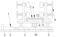
In the figure: the device comprises a support 1, a bottom plate 2, a hydraulic cylinder 3, a movable plate 4, a baffle 5, a top plate 6, a rotating device 7, a speed regulating motor 70, a universal ball 71, a circular plate 72, a limiting device 8, a connecting block 80, a spring 81, a pin rod 82, a clamping piece 9, a supporting block 90, a screw rod 91 and a clamping block 92.
Detailed Description
The technical solutions in the embodiments of the present invention will be clearly and completely described below with reference to the drawings in the embodiments of the present invention, and it is obvious that the described embodiments are only a part of the embodiments of the present invention, and not all of the embodiments. All other embodiments, which can be derived by a person skilled in the art from the embodiments given herein without making any creative effort, shall fall within the protection scope of the present invention.
Unless otherwise indicated, all references to up, down, left, right, front, back, inner and outer directions herein are to be interpreted as referring to up, down, left, right, front, back, inner and outer directions in the drawings to which the invention is directed.
The invention provides a welding fixture for manufacturing an oil cylinder as shown in figures 1-3, which comprises a bracket 1, a rotating device 7, a limiting device 8 and a clamping piece 9, the support 1 comprises a bottom plate 2, a hydraulic cylinder 3 and a movable plate 4, the hydraulic cylinder 3 is fixed on the top wall of the bottom plate 2 through bolts, the hydraulic cylinder 3 adopts an electric hydraulic cylinder which is manufactured by Texas Laplace numerical control mechanical equipment and is of PLS-200 type, a piston rod of the hydraulic cylinder 3 is welded with one side of a movable plate 4, a plurality of groups of rollers are arranged on the bottom wall of the movable plate 4, two groups of baffles 5 are welded on the top wall of the movable plate 4, the top ends of the two groups of baffles 5 are connected with a top plate 6, the roof of roof 6 is fixed with rotary device 7, stop device 8 and holder 9, holder 9 is provided with two sets ofly, rotary device 7 and stop device 8 all are located between two sets of holders 9.
Specifically, the rotating device 7 comprises a speed regulating motor 70, universal balls 71 and a circular plate 72, wherein the speed regulating motor 70 is fixed on the bottom wall of the top plate 6 through bolts, the speed regulating motor 70 is a speed regulating motor which is made by Wuxi Pioneer motor company Limited and has a model of YCT90-4A, an output shaft of the speed regulating motor 70 penetrates through the top plate 6 and is connected with the bottom wall of the circular plate 72 through a flange, the output shaft of the speed regulating motor 70 is welded with the flange, the flange is connected with the circular plate 72 through bolts, an anti-slip pad is bonded on the top wall of the circular plate 72, a plurality of groups of universal balls are arranged on the bottom wall of the circular plate 72, connecting seats of the plurality of groups of universal balls are welded with the circular plate 72, a plurality of groups of clamping grooves are formed in the side wall of the circular plate 72, and the output.
Specifically, stop device 8 includes connecting block 80, spring 81 and pin rod 82, one side of connecting block 80 is seted up flutedly, is provided with spring 81 in the recess, and connecting block 80 welds the roof of roof 6, the one end of pin rod 82 runs through the lateral wall of connecting block 80, the other end integrated into one piece of pin rod 82 has the pull ring, the outer wall integrated into one piece of pin rod 82 has the dog, the outside of pin rod 82 is entangled to spring 81, the draw-in groove of plectane 72 lateral wall is inserted to the one end of pin rod 82, the pulling pull ring, and the one end of pin rod 82 is deviate from in the draw-in groove of plectane 72 lateral wall, does benefit to the rotation of plectane 72, loosens the pull ring, and spring 81 promotes dog and pin rod 82 and removes, makes the draw-in groove of one end insertion plectane 72 lateral wall of pin rod.
Specifically, holder 9 includes supporting shoe 90, lead screw 91 and fixture block 92, supporting shoe 90 is L shape, the cushion has been welded with the junction of vertical section to the horizontal segment of supporting shoe 90, two sets of and the through-hole of sleeve adaptation have been seted up to the vertical section of supporting shoe 90, equal threaded connection has lead screw 91 in two sets of sleeves, and two sets of sleeves all weld with supporting shoe 90, and are two sets of equal swivelling joint of tip of lead screw 91 has fixture block 92, and is two sets of the arc wall has all been seted up to one side that lead screw 91 was kept away from to fixture block 92, and it has the cushion to bond in the arc wall, and two sets of the one end that fixture block 92 was kept away from to lead screw 91 has all welded two sets of barres, holds rotatory lead screw 91 of barre, and four sets of lead screw 91 in two sets of holders 9 combine.
Specifically, the top wall of bottom plate 2 is seted up the spout of multiunit and gyro wheel adaptation, and is two sets of the lateral wall of baffle 5 has all welded multiunit right angle triangle-shaped board.
Specifically, the welding fixture for manufacturing the oil cylinder vertically places the oil cylinder on an anti-slip pad on the top wall of the circular plate 72, holds a handle rod to rotate a screw rod 91, four groups of screw rods 91 in two groups of clamping parts 9 are combined with clamping blocks 92 to clamp oil cylinders of different models, if the orientation and the position of the oil cylinder need to be adjusted, rotates the screw rod 91 in one group of clamping parts 9 to separate two groups of clamping blocks 92 from the oil cylinder, pulls a pull ring, one end of a pin rod 82 is separated from a clamping groove on the side wall of the circular plate 72, an output shaft of an adjustable speed motor 70 drives the circular plate 72 and the oil cylinder on the circular plate 72 to rotate, the orientation of the oil cylinder can be adjusted, the pull ring is released, a spring 81 pushes the clamping blocks and the pin rod 82 to move, one end of the pin rod 82 is inserted into the clamping groove on the side wall of the circular plate 72 to fix the circular plate 72, rotates the, thereby adjusting the position of the oil cylinder and being beneficial to welding different parts of the oil cylinder.
Finally, it should be noted that: although the present invention has been described in detail with reference to the foregoing embodiments, it will be apparent to those skilled in the art that modifications may be made to the embodiments or portions thereof without departing from the spirit and scope of the invention.
Claims (5)
1. The utility model provides a welding jig is used in hydro-cylinder manufacturing, includes support (1), rotary device (7), stop device (8) and holder (9), its characterized in that: support (1) includes bottom plate (2), pneumatic cylinder (3) and fly leaf (4), the roof of bottom plate (2) is fixed with pneumatic cylinder (3), the piston rod of pneumatic cylinder (3) is connected with one side of fly leaf (4), the multiunit gyro wheel is installed to the diapire of fly leaf (4), the roof welding of fly leaf (4) has two sets of baffle (5), and is two sets of the top of baffle (5) all is connected with roof (6), the roof of roof (6) is fixed with rotary device (7), stop device (8) and holder (9), holder (9) are provided with two sets ofly, rotary device (7) and stop device (8) all are located between two sets of holders (9).
2. The welding jig for manufacturing a cylinder according to claim 1, characterized in that: the rotary device (7) comprises an adjustable speed motor (70), universal balls (71) and a circular plate (72), wherein the adjustable speed motor (70) is fixed on the bottom wall of the top plate (6), an output shaft of the adjustable speed motor (70) penetrates through the bottom wall of the top plate (6) and is connected with the bottom wall of the circular plate (72) through a flange, a non-slip mat is fixed on the top wall of the circular plate (72), the bottom wall of the circular plate (72) is provided with multiple groups of universal balls, and multiple groups of clamping grooves are formed in the side wall of the circular plate (72).
3. The welding jig for manufacturing a cylinder according to claim 1, characterized in that: stop device (8) are including connecting block (80), spring (81) and pin rod (82), one side of connecting block (80) is seted up flutedly, is provided with spring (81) in the recess, the one end through connection piece (80) lateral wall of pin rod (82), the other end integrated into one piece of pin rod (82) has the pull ring, the outer wall integrated into one piece of pin rod (82) has the dog, the outside of pin rod (82) is entangled in spring (81), the draw-in groove of plectane (72) lateral wall is inserted to the one end of pin rod (82).
4. The welding jig for manufacturing a cylinder according to claim 1, characterized in that: holder (9) are including supporting shoe (90), lead screw (91) and fixture block (92), supporting shoe (90) are L shape, the horizontal segment of supporting shoe (90) has the cushion with the junction welding of vertical section, two sets of and the through-hole of sleeve adaptation are seted up to the vertical section of supporting shoe (90), and equal threaded connection has lead screw (91) in two sets of sleeves, and is two sets of the equal swivelling joint of tip of lead screw (91) has fixture block (92), and is two sets of the arc wall has all been seted up to one side that lead screw (91) were kept away from in fixture block (92), and it has the cushion to bond in the arc wall, and is two sets of the one end that fixture block (92) were kept away from in lead screw (91) has.
5. The welding jig for manufacturing a cylinder according to claim 1, characterized in that: the top wall of the bottom plate (2) is provided with a plurality of groups of sliding grooves matched with the rollers, and the side walls of the baffle plates (5) are welded with a plurality of groups of right-angled triangular plates.
Priority Applications (1)
| Application Number | Priority Date | Filing Date | Title |
|---|---|---|---|
| CN201911251708.3A CN110773945A (en) | 2019-12-09 | 2019-12-09 | Welding fixture for manufacturing oil cylinder |
Applications Claiming Priority (1)
| Application Number | Priority Date | Filing Date | Title |
|---|---|---|---|
| CN201911251708.3A CN110773945A (en) | 2019-12-09 | 2019-12-09 | Welding fixture for manufacturing oil cylinder |
Publications (1)
| Publication Number | Publication Date |
|---|---|
| CN110773945A true CN110773945A (en) | 2020-02-11 |
Family
ID=69394919
Family Applications (1)
| Application Number | Title | Priority Date | Filing Date |
|---|---|---|---|
| CN201911251708.3A Withdrawn CN110773945A (en) | 2019-12-09 | 2019-12-09 | Welding fixture for manufacturing oil cylinder |
Country Status (1)
| Country | Link |
|---|---|
| CN (1) | CN110773945A (en) |
Cited By (2)
| Publication number | Priority date | Publication date | Assignee | Title |
|---|---|---|---|---|
| CN112388237A (en) * | 2021-01-19 | 2021-02-23 | 西安贝伦环保科技有限公司 | Automobile door welding frame |
| CN112847195A (en) * | 2021-01-05 | 2021-05-28 | 杨淑媛 | Adjustable clamping device for steel processing |
-
2019
- 2019-12-09 CN CN201911251708.3A patent/CN110773945A/en not_active Withdrawn
Cited By (3)
| Publication number | Priority date | Publication date | Assignee | Title |
|---|---|---|---|---|
| CN112847195A (en) * | 2021-01-05 | 2021-05-28 | 杨淑媛 | Adjustable clamping device for steel processing |
| CN112847195B (en) * | 2021-01-05 | 2023-01-17 | 湖南中部智能制造有限公司 | Adjustable clamping device for steel processing |
| CN112388237A (en) * | 2021-01-19 | 2021-02-23 | 西安贝伦环保科技有限公司 | Automobile door welding frame |
Similar Documents
| Publication | Publication Date | Title |
|---|---|---|
| CN201792117U (en) | Automatic rotary welding device | |
| CN211840813U (en) | Novel rapid welding equipment | |
| CN204487039U (en) | Universal Tube-sheet Welding equipment | |
| CN205342605U (en) | Lathe with impulse type tool magazine device | |
| CN110773945A (en) | Welding fixture for manufacturing oil cylinder | |
| CN105710518A (en) | Hollow bolt ball welding tool | |
| CN205342608U (en) | Cantilever lathe with impulse type tool magazine device | |
| CN205342604U (en) | Cantilever lathe with tool magazine device | |
| CN207139363U (en) | A kind of adjustable large diameter circular arc plate fixture of three-dimensional | |
| CN204339156U (en) | For the welding gun governor motion of automatic welding device | |
| CN211162683U (en) | Welding fixture for manufacturing oil cylinder | |
| CN203579153U (en) | Balance arm mechanism for vertical assembly | |
| CN205342472U (en) | Cantilever lathe with rotation type workstation | |
| CN207479736U (en) | Pipe fitting sawing circular saw bench | |
| CN219464853U (en) | Milling machine for processing iron tower bottom plate | |
| CN202278210U (en) | Machining boring machine for differential housing | |
| CN109277608B (en) | Double-milling-head machining device | |
| CN107263107B (en) | Automatic processing equipment for steel pipe joint | |
| CN204339155U (en) | Rotary transverse tube special welding machine | |
| CN210615910U (en) | Tool changing device for milling machine | |
| CN216138624U (en) | Centre bore grinding device is used in processing of axle type gear | |
| CN204954122U (en) | Small -size pipe cutting machine | |
| CN107263192A (en) | Guiding polypody is creeped feeding with high precision drive shaft mechanism | |
| CN107695734A (en) | A kind of adjustable large diameter circular arc plate fixture of three-dimensional | |
| CN205869830U (en) | Automobile part tool fixture |
Legal Events
| Date | Code | Title | Description |
|---|---|---|---|
| PB01 | Publication | ||
| PB01 | Publication | ||
| WW01 | Invention patent application withdrawn after publication |
Application publication date: 20200211 |
|
| WW01 | Invention patent application withdrawn after publication |