CN110761283A - Anchor rod compensation tensioning device - Google Patents
Anchor rod compensation tensioning device Download PDFInfo
- Publication number
- CN110761283A CN110761283A CN201911230947.0A CN201911230947A CN110761283A CN 110761283 A CN110761283 A CN 110761283A CN 201911230947 A CN201911230947 A CN 201911230947A CN 110761283 A CN110761283 A CN 110761283A
- Authority
- CN
- China
- Prior art keywords
- anchor
- existing
- locking
- hole
- rod
- Prior art date
- Legal status (The legal status is an assumption and is not a legal conclusion. Google has not performed a legal analysis and makes no representation as to the accuracy of the status listed.)
- Pending
Links
Images


Classifications
-
- E—FIXED CONSTRUCTIONS
- E02—HYDRAULIC ENGINEERING; FOUNDATIONS; SOIL SHIFTING
- E02D—FOUNDATIONS; EXCAVATIONS; EMBANKMENTS; UNDERGROUND OR UNDERWATER STRUCTURES
- E02D5/00—Bulkheads, piles, or other structural elements specially adapted to foundation engineering
- E02D5/74—Means for anchoring structural elements or bulkheads
-
- E—FIXED CONSTRUCTIONS
- E02—HYDRAULIC ENGINEERING; FOUNDATIONS; SOIL SHIFTING
- E02D—FOUNDATIONS; EXCAVATIONS; EMBANKMENTS; UNDERGROUND OR UNDERWATER STRUCTURES
- E02D2250/00—Production methods
- E02D2250/0046—Production methods using prestressing techniques
Landscapes
- Engineering & Computer Science (AREA)
- Structural Engineering (AREA)
- Life Sciences & Earth Sciences (AREA)
- General Life Sciences & Earth Sciences (AREA)
- Mining & Mineral Resources (AREA)
- Paleontology (AREA)
- Civil Engineering (AREA)
- General Engineering & Computer Science (AREA)
- Piles And Underground Anchors (AREA)
Abstract
本发明提供了一种锚杆补张拉装置,涉及岩土锚固技术领域,用于对腰梁上的既有锚具进行补张拉施工,包括第一锚具、第二锚具、吊杆和承载架,承载架包括支撑腿和承载部,承载部上设置有通孔,吊杆套设在通孔内,吊杆远离既有锚具的一侧设置有第一锚具,第一锚具和承载部之间设置有驱动机构;驱动机构用于驱动第一锚具带动吊杆向远离既有锚具方向移动;吊杆靠近既有锚具的一侧与第二锚具连接,第二锚具上设置有环孔,其套设在既有锚具的外侧,且与既有锚具的外壁抵接。本发明提供的锚杆补张拉装置能够直接将既有锚具拉起,适用于锚杆外露杆体破坏或长度不足的情况,且不限杆体外露长度,使用范围广,除第二锁片以外其余部分均可重复利用。
The invention provides an anchor rod supplementary tensioning device, which relates to the technical field of geotechnical anchoring and is used for supplementary tensioning construction of existing anchorages on waist beams, including a first anchorage, a second anchorage and a hanger rod. and a bearing frame, the bearing frame includes a support leg and a bearing part, the bearing part is provided with a through hole, the boom is sleeved in the through hole, and the side of the boom away from the existing anchor is provided with a first anchor, the first anchor A driving mechanism is arranged between the tool and the bearing part; the driving mechanism is used to drive the first anchor to drive the boom to move away from the existing anchor; the side of the boom close to the existing anchor is connected to the second anchor, The second anchor is provided with an annular hole, which is sleeved on the outer side of the existing anchor and abuts with the outer wall of the existing anchor. The anchor rod supplementary tensioning device provided by the invention can directly pull up the existing anchor, and is suitable for the situation that the exposed rod body of the anchor rod is damaged or the length is insufficient, and the exposed length of the rod body is not limited, and the application range is wide, except for the second locking piece. The rest can be reused.
Description
技术领域technical field
本发明涉及岩土锚固技术领域,尤其是涉及一种锚杆补张拉装置。The invention relates to the technical field of rock-soil anchoring, in particular to an anchor rod supplementary tension device.
背景技术Background technique
锚杆支护是目前岩土工程中常用的支护形式。锚杆设计施工时,通常设置锚杆自由段,并施加预应力以增加支护结构刚度,限制岩土体变形。预应力施加往往通过锚杆张拉实现。锚杆张拉时,先将外露杆体穿过成品锁具,再穿过穿心千斤顶,并将其端部用辅助锚具锁住,利用千斤顶顶升辅助锚具,实现杆体张拉。张拉完成后,利用千斤顶底部的成品锁具锁住外露杆体,卸去千斤顶,完成锚杆张拉工作。Bolt support is a commonly used form of support in geotechnical engineering. During the design and construction of the bolt, the free section of the bolt is usually set, and prestress is applied to increase the rigidity of the supporting structure and limit the deformation of the rock and soil mass. Prestressing is often achieved by bolt tensioning. When the anchor rod is tensioned, first pass the exposed rod body through the finished lock, and then pass through the core jack, and lock its end with an auxiliary anchor, and use the jack to lift the auxiliary anchor to realize the tension of the rod. After the tensioning is completed, use the finished lock at the bottom of the jack to lock the exposed rod body, remove the jack, and complete the anchor rod tensioning work.
随着支护结构使用时间的增加,由于岩土体变形或者杆体徐变,锚杆的杆体往往会出现预应力损失的现象。为了支护结构的安全使用,需要对锚杆进行补张拉。With the increase of the service time of the supporting structure, the prestress loss of the rod body of the anchor rod often occurs due to the deformation of the rock and soil mass or the creep of the rod body. For the safe use of the support structure, the anchor rod needs to be supplemented and tensioned.
常规的张拉、锁定过程需要外露杆体足够长(一般不小于100cm),因此锚杆张拉完成后,对于没有剪除锚具外侧预留杆体的锚杆,可以通过常规方法对锚杆重新张拉锁定。为了增加施工空间而往往将锚具外侧预留的杆体剪断,这种情况下,常规的张拉方法不再适用。此外,当采用钢绞线作为锚杆杆体时,可能因施工问题使预留钢绞线被破坏。其端部因散开或弯折而无法顺利穿过锚具或千斤顶,同样无法使用常规方法进行补张拉施工。The conventional tensioning and locking process requires the exposed rod body to be long enough (generally not less than 100cm), so after the anchor rod tensioning is completed, for the anchor rod without the reserved rod body on the outside of the anchor, the anchor rod can be re-tensioned by conventional methods. locking. In order to increase the construction space, the rod body reserved outside the anchor is often cut off. In this case, the conventional tensioning method is no longer applicable. In addition, when the steel strand is used as the bolt body, the reserved steel strand may be damaged due to construction problems. The ends cannot pass through the anchors or jacks smoothly due to being scattered or bent, and it is also impossible to use conventional methods for supplementary tensioning construction.
发明内容SUMMARY OF THE INVENTION
本发明的目的在于提供一锚杆补张拉装置,以解决既有锚具外侧预留的杆体剪断或者因施工问题使预留钢绞线被破坏,其端部无法顺利穿过锚具或千斤顶时,无法使用常规方法进行补张拉施工的技术问题。The purpose of the present invention is to provide an anchor rod supplementary tension device to solve the problem that the rod body reserved outside the existing anchor is cut or the reserved steel strand is damaged due to construction problems, and its end cannot smoothly pass through the anchor or the jack , the technical problem that the conventional method cannot be used for supplementary tension construction.
本发明提供的锚杆补张拉装置,用于对腰梁上的既有锚具进行补张拉施工,所述锚杆补张拉装置包括第一锚具、第二锚具、吊杆和承载架,所述承载架包括支撑腿和承载部,所述承载部上设置有通孔,所述吊杆套设在所述通孔内;The anchor rod supplementary tensioning device provided by the present invention is used for supplementary tensioning construction of the existing anchors on the waist beam, and the anchor rod supplementary tensioning device comprises a first anchorage, a second anchorage, a boom and a a carrying frame, the carrying frame includes a support leg and a carrying part, the carrying part is provided with a through hole, and the hanger rod is sleeved in the through hole;
所述吊杆远离所述既有锚具的一侧设置有第一锚具,所述第一锚具和所述承载部之间设置有驱动机构;所述驱动机构用于驱动所述第一锚具带动所述吊杆向远离所述既有锚具的方向移动;A first anchor is arranged on the side of the hanger away from the existing anchor, and a drive mechanism is arranged between the first anchor and the bearing part; the drive mechanism is used to drive the first anchor The anchor drives the boom to move away from the existing anchor;
所述吊杆靠近所述既有锚具的一侧与第二锚具连接,所述第二锚具上设置有环孔,其套设在所述既有锚具的外侧,且与所述既有锚具的外壁抵接。The side of the hanger close to the existing anchor is connected with a second anchor, and the second anchor is provided with a ring hole, which is sleeved on the outer side of the existing anchor and is connected to the second anchor. The outer wall of the existing anchor abuts.
进一步的,所述第二锚具与所述既有锚具之间设置有轴向锁止机构,当所述驱动机构驱动所述第一锚具通过吊杆带动所述第二锚具向远离所述既有锚具的方向移动时,用于在所述吊杆的长度方向上将所述第二锚具与所述既有锚具之间的移动锁止。Further, an axial locking mechanism is provided between the second anchor and the existing anchor. When the driving mechanism drives the first anchor to drive the second anchor away from the boom through the boom, an axial locking mechanism is provided. When the direction of the existing anchor is moved, it is used to lock the movement between the second anchor and the existing anchor in the length direction of the boom.
进一步的,所述轴向锁止机构包括第一锁片和第二锁片,所述第二锁片与所述既有锚具的外侧壁连接;所述第二锁片的外侧壁与所述第一锁片的内侧壁连接;所述第一锁片的外侧壁与所述第二锚具上的所述环孔连接;Further, the axial locking mechanism includes a first locking piece and a second locking piece, the second locking piece is connected with the outer side wall of the existing anchor; the outer side wall of the second locking piece is connected with the The inner side wall of the first locking piece is connected; the outer side wall of the first locking piece is connected with the ring hole on the second anchor;
所述第一锁片与所述第一锁片配合,所述第二锚具与所述第一锁片配合,以使所述第二锚具朝向所述第一锚具方向移动时,能够带动所述既有锚具朝向所述第一锚具方向移动。The first locking piece is matched with the first locking piece, and the second anchor is matched with the first locking piece, so that when the second anchor moves in the direction of the first anchor, it can The existing anchor is driven to move toward the direction of the first anchor.
进一步的,所述第一锁片的内侧壁上设置有第一锥孔,所述第二锁片的外侧壁上设置有与所述第一锥孔对应的第一锥形结构;所述第二锁片插装在所述第一锥孔内;Further, the inner side wall of the first locking piece is provided with a first tapered hole, and the outer side wall of the second locking piece is provided with a first tapered structure corresponding to the first tapered hole; The second locking piece is inserted into the first tapered hole;
所述环孔包括第二锥孔,所述第一锁片的外侧壁上设置有第二锥形结构,所述第一锁片插装在所述第二锥孔内;The annular hole includes a second tapered hole, a second tapered structure is provided on the outer side wall of the first locking piece, and the first locking piece is inserted into the second tapered hole;
沿所述既有锚具朝向所述第一锚具方向,所述第一锥孔和所述第二锥孔的直径逐渐增大,且所述第一锥孔下端的直径小于所述第一锥形结构上端的直径;所述第二锥孔下端的直径小于所述第二锥形结构上端的直径。The diameter of the first tapered hole and the second tapered hole gradually increases along the direction of the existing anchor toward the first anchor, and the diameter of the lower end of the first tapered hole is smaller than that of the first tapered hole. The diameter of the upper end of the tapered structure; the diameter of the lower end of the second tapered hole is smaller than the diameter of the upper end of the second tapered structure.
进一步的,所述环孔包括圆孔,所述圆孔与所述第二锥孔的上端面连接,所述第一锁片的外侧壁上设置有与所述圆孔对应的柱状结构,所述柱状结构连接在所述第二锥形结构的上端面;Further, the annular hole includes a circular hole, the circular hole is connected with the upper end surface of the second tapered hole, and the outer side wall of the first locking piece is provided with a columnar structure corresponding to the circular hole, so the columnar structure is connected to the upper end face of the second conical structure;
所述圆孔的高度与所述柱状结构的高度相等。The height of the circular hole is equal to the height of the columnar structure.
进一步的,所述第二锚具的高度小于所述既有锚具的高度。Further, the height of the second anchor is smaller than the height of the existing anchor.
进一步的,所述第一锁片包括多个第一子锁片,多个所述第一子锁片围成环形,形成所述第一锁片;Further, the first locking piece includes a plurality of first sub-locking pieces, and the plurality of first sub-locking pieces are encircled in a ring shape to form the first locking piece;
所述第二锁片包括多个第二子锁片,多个所述第二子锁片围成环形,形成所述第二锁片。The second locking piece includes a plurality of second sub-locking pieces, and the plurality of the second sub-locking pieces are encircled in a ring shape to form the second locking piece.
进一步的,所述第一锁片包括四个所述第一子锁片;所述第二锁片包括四个所述第二子锁片。Further, the first locking piece includes four first sub-locking pieces; the second locking piece includes four second sub-locking pieces.
进一步的,所述锚杆补张拉装置还包括测力计和第三锚具,所述测力计和所述第三锚具套设在所述吊杆上,且所述测力计的一端与所述承载部抵接,另一端与所述第三锚具的底面抵接,所述第三锚具的顶面与所述驱动机构的下端面抵接。Further, the anchor rod supplementary tension device further includes a dynamometer and a third anchor, the dynamometer and the third anchor are sleeved on the hanger, and the dynamometer is One end is in contact with the bearing portion, the other end is in contact with the bottom surface of the third anchor, and the top surface of the third anchor is in contact with the lower end surface of the driving mechanism.
进一步的,所述驱动机构为空心千斤顶。Further, the driving mechanism is a hollow jack.
本发明提供的锚杆补张拉装置,用于对腰梁上的既有锚具进行补张拉施工,所述锚杆补张拉装置包括第一锚具、第二锚具、吊杆和承载架,所述承载架包括支撑腿和承载部,所述承载部上设置有通孔,所述吊杆套设在所述通孔内;所述吊杆远离所述既有锚具的一侧设置有第一锚具,所述第一锚具和所述承载部之间设置有驱动机构;所述驱动机构用于驱动所述第一锚具带动所述吊杆向远离所述既有锚具的方向移动;所述吊杆靠近所述既有锚具的一侧与第二锚具连接,所述第二锚具上设置有环孔,其套设在所述既有锚具的外侧,且与所述既有锚具的外壁抵接。使用时,将第二锚具的环孔与既有锚具的外壁抵接,吊杆与第二锚具连接,将承载架套设在所述吊杆上,然后在吊杆套装驱动机构和第一锚具,第一锚具与吊杆固结,驱动机构设置在第一锚具和承载架的承载板之间,驱动机构能够驱动第一锚具带动吊杆向远离所述既有锚具方向移动,以使与吊杆连接的第二锚具能够带动既有锚具向远离腰梁方向运动,当锚杆张拉至设计值时,在所述既有锚具与腰梁之间重新加入垫板,从而实现对锚杆进行补张拉施工。本发明提供的锚杆补张拉装置直接将既有锚具拉起,适用于锚杆外露杆体破坏或长度不足的情况,且不限杆体外露长度,使用范围广。The anchor rod supplementary tensioning device provided by the present invention is used for supplementary tensioning construction of the existing anchors on the waist beam, and the anchor rod supplementary tensioning device comprises a first anchorage, a second anchorage, a boom and a a carrying frame, the carrying frame includes a support leg and a bearing part, the carrying part is provided with a through hole, and the hanger rod is sleeved in the through hole; the hanger rod is far away from a part of the existing anchorage A first anchor is arranged on the side, and a drive mechanism is arranged between the first anchor and the bearing portion; the drive mechanism is used to drive the first anchor to drive the boom to move away from the existing The direction of the anchorage moves; the side of the boom close to the existing anchorage is connected with the second anchorage, and the second anchorage is provided with a ring hole, which is sleeved on the existing anchorage. outside, and abuts with the outer wall of the existing anchor. When in use, the ring hole of the second anchor is abutted with the outer wall of the existing anchor, the boom is connected with the second anchor, the bearing frame is sleeved on the boom, and then the drive mechanism and the boom are installed on the boom. The first anchor, the first anchor is fixed with the boom, the driving mechanism is arranged between the first anchor and the bearing plate of the bearing frame, and the driving mechanism can drive the first anchor to drive the boom to move away from the existing anchor The tool moves in the direction so that the second anchor connected to the boom can drive the existing anchor to move away from the waist beam. When the anchor is stretched to the design value, between the existing anchor and the waist beam Re-join the backing plate, so as to realize the supplementary tension construction of the bolt. The bolt supplementary tensioning device provided by the present invention directly pulls up the existing anchor, and is suitable for the situation that the exposed rod body of the anchor rod is damaged or the length is insufficient, and the exposed length of the rod body is not limited, and the application range is wide.
附图说明Description of drawings
为了更清楚地说明本发明具体实施方式或现有技术中的技术方案,下面将对具体实施方式或现有技术描述中所需要使用的附图作简单地介绍,显而易见地,下面描述中的附图是本发明的一些实施方式,对于本领域普通技术人员来讲,在不付出创造性劳动的前提下,还可以根据这些附图获得其他的附图。In order to illustrate the specific embodiments of the present invention or the technical solutions in the prior art more clearly, the following briefly introduces the accompanying drawings that need to be used in the description of the specific embodiments or the prior art. Obviously, the accompanying drawings in the following description The drawings are some embodiments of the present invention. For those of ordinary skill in the art, other drawings can also be obtained based on these drawings without creative efforts.
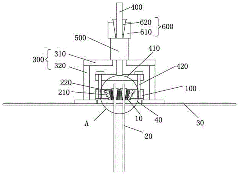
图1为本发明实施例提供的锚杆补张拉装置的结构示意图;1 is a schematic structural diagram of a bolt supplementary tensioning device provided in an embodiment of the present invention;
图2为图1中的A部放大图;Fig. 2 is the enlarged view of A part in Fig. 1;
图3为本发明实施例提供的锚杆补张拉装置的拆解图;3 is a disassembled view of the anchor rod supplementary tensioning device provided by the embodiment of the present invention;
图4为本发明实施例提供的锚杆补张拉装置的吊杆与第二锚具的连接示意图;4 is a schematic diagram of the connection between the boom and the second anchor of the anchor rod supplementary tensioning device provided by the embodiment of the present invention;
图5为本发明实施例提供的锚杆补张拉装置的吊杆与第二锚具的爆炸图;5 is an exploded view of the boom and the second anchor of the anchor rod supplementary tensioning device provided by the embodiment of the present invention;
图6为本发明实施例提供的锚杆补张拉装置的测力计的安装示意图。FIG. 6 is a schematic diagram of the installation of the dynamometer of the bolt supplementary tensioning device according to the embodiment of the present invention.
图标:10-既有锚具;11-既有锚具锁片;20-锚杆;30-腰梁;40-既有垫板;100-第二锚具;110-环孔;120-螺孔;210-第一锁片;211-第一子锁片;220-第二锁片;221-第二子锁片;300-承载架;310-承载部;320-支撑腿;400-吊杆;410-过渡板;411-安装孔;420-螺杆;500-驱动机构;600-第一锚具;610-锚具本体;620-锚具锁片;700-测力计;800-第三锚具。Icon: 10-existing anchorage; 11-existing anchorage locking piece; 20-anchor rod; 30-waist beam; 40-existing backing plate; 100-second anchorage; 110-ring hole; 120-screw Hole; 210-first locking piece; 211-first sub-locking piece; 220-second locking piece; 221-second sub-locking piece; 300-carrying frame; 310-bearing part; 320-supporting leg; 400-hanging Rod; 410-transition plate; 411-installation hole; 420-screw; 500-drive mechanism; 600-first anchor; 610-anchor body; 620-anchor lock plate; 700-dynamometer; 800-first Three anchors.
具体实施方式Detailed ways
下面将结合实施例对本发明的技术方案进行清楚、完整地描述,显然,所描述的实施例是本发明一部分实施例,而不是全部的实施例。基于本发明中的实施例,本领域普通技术人员在没有做出创造性劳动前提下所获得的所有其他实施例,都属于本发明保护的范围。The technical solutions of the present invention will be clearly and completely described below with reference to the embodiments. Obviously, the described embodiments are part of the embodiments of the present invention, but not all of the embodiments. Based on the embodiments of the present invention, all other embodiments obtained by those of ordinary skill in the art without creative efforts shall fall within the protection scope of the present invention.
如图1-图6所示,本发明提供的锚杆补张拉装置,用于对腰梁30上的既有锚具10进行补张拉施工,锚杆补张拉装置包括第一锚具600、第二锚具100、吊杆400和承载架300,承载架300包括支撑腿320和承载部310,承载部310上设置有通孔,吊杆400套设在通孔内。As shown in FIGS. 1 to 6 , the bolt supplementary tensioning device provided by the present invention is used to perform supplementary tension construction on the existing
吊杆400远离既有锚具10的一侧设置有第一锚具600,第一锚具600和承载部310之间设置有驱动机构500,驱动机构500用于驱动第一锚具600带动吊杆400向远离既有锚具10的方向移动。A
吊杆400靠近既有锚具10的一侧与第二锚具100连接,第二锚具100上设置有环孔110,第二锚具100套设在既有锚具10的外侧,且与既有锚具10的外壁抵接。The side of the
具体地,腰梁30上设置有既有垫板40,锚杆20依次穿过腰梁30与既有垫板40后通过既有锚具10固定。Specifically, an existing
吊杆400穿过承载架300上的通孔,将承载架300的支撑腿320放置在腰梁30上,吊杆400依次穿过驱动机构500和第一锚具600。第一锚具600包括锚具本体610和锚具锁片620,锚具本体610通过锚具锁片620与吊杆400连接,锚具锁片620将锚具本体610与吊杆400锁定。The
吊杆400靠近既有锚具10的一侧设置有过渡板410,过渡板410上设置有安装孔411,第二锚具100上设置有与安装孔411对应的螺孔120,过渡板410与第二锚具100通过螺杆420连接,以使吊杆400能够带动第二锚具100移动。The side of the
使用时,将第二锚具100的环孔110与既有锚具10的外壁抵接,吊杆400与第二锚具100连接,将承载架300套设在吊杆400上,然后在吊杆400上套装驱动机构500和第一锚具600,第一锚具600与吊杆400锁定,驱动机构500设置在第一锚具600和承载架300的承载板之间,驱动机构500能够驱动第一锚具600带动吊杆400向远离既有锚具10方向移动,以使与吊杆400连接的第二锚具100能够带动既有锚具10向远离腰梁30方向运动,当锚杆20张拉至设计值时,在既有锚具10与腰梁30之间加入垫板,然后,依次取下第一锚具600、驱动机构500、承载架300、螺杆420、吊杆400;取出第一锁片210和第二锚具100,施工完成,从而实现对锚杆20进行补张拉施工。In use, the
本发明提供的锚杆补张拉装置能够直接将既有锚具10拉起,适用于锚杆20外露杆体破坏或长度不足的情况,且不限杆体外露长度,使用范围广,除第二锁片220以外其余部分均可重复利用,符合节能环保、绿色施工的要求。The anchor rod supplement and tension device provided by the present invention can directly pull up the existing
优选地,驱动机构500可以为空心千斤顶。Preferably, the
进一步地,第二锚具100与既有锚具10之间设置有轴向锁止机构,当驱动机构500驱动第一锚具600通过吊杆400带动第二锚具100向远离既有锚具10的方向移动时,用于在吊杆400的长度方向上将第二锚具100与既有锚具10之间的移动锁止。Further, an axial locking mechanism is provided between the
如图1、图2所示,轴向锁止机构包括第一锁片210和第二锁片220,第二锁片220与既有锚具10的外侧壁连接;第二锁片220的外侧壁与第一锁片210的内侧壁连接;第一锁片210的外侧壁与第二锚具100上的环孔110连接。As shown in Figures 1 and 2, the axial locking mechanism includes a
第一锁片210与第一锁片210配合,第二锚具100与第一锁片210配合,以使第二锚具100朝向第一锚具600方向移动时,能够带动既有锚具10朝向第一锚具600方向移动。The
具体地,第二锁片220焊接在既有锚具10的外侧壁上,第二锚具100套设在既有锚具10上,第一锁片210设置在第二锁片220和第二锚具100的环孔110之间,用于在吊杆400带动第二锚具100向上移动时,将第二锚具100和既有锚具10之间锁定,从而能够带动既有锚具10向远离腰梁30的方向移动,由于第二锚具100通过第一锁片210和第二锁片220与既有锚具10连接,所以既有锚具10也能够随着吊杆400的移动而移动,从而在既有锚具10与腰梁30之间产生间隙,当锚杆20张拉至设计值时,在既有锚具10与既有垫板40之间的间隙内插入第一垫板,完成补张拉施工。Specifically, the
进一步地,第一锁片210的内侧壁上设置有第一锥孔,第二锁片220的外侧壁上设置有与第一锥孔对应的第一锥形结构;第二锁片220插装在第一锥孔内。Further, the inner side wall of the
环孔110包括第二锥孔,第一锁片210的外侧壁上设置有第二锥形结构,第一锁片210插装在所述第二锥孔内。The
沿既有锚具10朝向第一锚具600方向,第一锥孔和第二锥孔的直径逐渐增大,且第一锥孔下端的直径小于第一锥形结构上端的直径;第二锥孔下端的直径小于第二锥形结构上端的直径。Along the direction of the existing
具体地,第二锁片220焊接在既有锚具10的外侧壁上,第一锁片210通过其内侧壁上的第一锥孔与第二锁片220外侧壁上的第一锥形结构配合,以及第二锚具100的第二锥孔与第一锁片210外侧壁上的第二锥形结构配合,当第二锚具100在吊杆400的带动下向上运动时,能够带动既有锚具10移动。Specifically, the
可选地,环孔110包括圆孔,圆孔与第二锥孔的上端面连接,第一锁片210的外侧壁上设置有与圆孔对应的柱状结构,柱状结构连接在第二锥形结构的上端面。Optionally, the
圆孔的高度与柱状结构的高度相等。The height of the circular hole is equal to the height of the columnar structure.
优选地,第二锚具100的高度小于既有锚具10的高度。Preferably, the height of the
具体地,第二锚具100的高度小于既有锚具10的高度,在实际使用时,第二锚具100与既有垫板40之间具有间隙,在补张拉施工完成后,可以通过敲击第二锚具100,使其重新落到既有垫板40上,再依次取出第一锁片210和第二锚具100,拆除第二锚具100更加方便。Specifically, the height of the
优选地,第一锁片210包括多个第一子锁片211,多个第一子锁片211围成环形,形成第一锁片210。Preferably, the
第二锁片220包括多个第二子锁片221,多个第二子锁片221围成环形,形成第二锁片220。The
具体地,第一锁片210包括多个第一子锁片211,围成环形后,其内侧壁形成第一锥孔,其外侧壁形成第二锥形结构;第二锁片220包括多个第二子锁片221,围成环形后,其外侧壁形成第一锥形结构。Specifically, the
多个第一子锁片211均匀焊接在既有锚具10的外侧壁上,多个第二子锁片221均匀设置在第一子锁片211和环孔110之间,当第二锚具100向上移动时,因第二锚具100通过第二锥孔与第一子锁片211的外侧壁抵接,第一子锁片211的内侧壁与第二子锁片221的外侧壁抵接,第二锚具100会产生一个朝向既有锚具10的径向力,从而增大第二锚具100与第一子锁片211之间、第一子锁片211与第二子锁片221之间的摩擦力,使得在补张拉时,第二锚具100与既有锚具10之间的连接更加紧密和稳定。The plurality of first
同时,多个第一子锁片211和第二子锁片221更加方便第二锚具100的拆装。Meanwhile, the plurality of first
如图5所示,本实施例中,第一锁片210包括四个第一子锁片211,第二锁片220包括四个第二子锁片221。As shown in FIG. 5 , in this embodiment, the
可选地,锚杆补张拉装置还包括测力计700和第三锚具800,测力计700和第三锚具800套设在吊杆400上,且测力计700的一端与承载部310抵接,另一端与第三锚具800的底面抵接,第三锚具800的顶面与驱动机构500的下端面抵接。Optionally, the bolt supplementary tensioning device further includes a
如图6所示,在上述的锚杆补张拉装置的驱动机构500和承载架300之间增加一个测力计700和第三锚具800,还可实现补张拉后锚杆20内力的实时监测,使用时,补张拉施工完成后,利用第三锁片将第三锚具800与吊杆400锁定,仅拆掉驱动机构500与第一锚具600,保留其他部件,可通过测力计700实时监测锚杆20的内力。As shown in FIG. 6 , adding a
本发明提供的锚杆补张拉装置,其工作方法为:(1)将锚杆20杆体外露端修剪至5cm以内;(2)将第二锁片220均匀焊接在既有锚具10的外侧壁上;(3)将第二锚具100套在既有锚具10上,使既有锚具10位于第二锚具100的中央,第二锚具100的底部与既有垫板40接触;(4)将第一锁片210均匀放入第二锚具100与第二锁片220之间的空隙;(5)将螺杆420穿过过渡板410上的安装孔411,使螺杆420与第二锚具100上的螺孔120连接;(6)将吊杆400穿过承载架300上的通孔,将承载架300的支撑脚放置在腰梁30上;使吊杆400依次穿过空心千斤顶与第一锚具600,并通过第一锁片210将第一锚具600与吊杆400锁定,通过空心千斤顶加压,将吊杆400向外提起;(7)空心千斤顶产生的压力通过第一锚具600转化为拉力,然后依次通过吊杆400、过渡板410、螺杆420、第二锚具100、第一锁片210、第二锁片220、既有锚具10、既有锚具锁片11传递给锚杆20杆体;(8)随着空心千斤顶压力的增加,既有锚具10与既有垫板40会逐渐分离,锚杆20张拉至设计值时,在既锚具与既有垫板40之间的缝隙内插入第一垫板;(9)卸载千斤顶,依次取下第一锚具600、空心千斤顶、承载架300、螺杆420和吊杆400;(10)敲击第二锚具100,使其与重新落到既有垫板40上,此时可以次取下第一锁片210与第二锚具100,施工完成。The bolt tensioning device provided by the present invention has the following working methods: (1) trimming the exposed end of the bolt body 20 to within 5 cm; (2) uniformly welding the second locking piece 220 to the outside of the existing anchor 10 (3) Set the second anchor 100 on the existing anchor 10, so that the existing anchor 10 is located in the center of the second anchor 100, and the bottom of the second anchor 100 is in contact with the existing backing plate 40 (4) Put the first locking piece 210 into the space between the second anchor 100 and the second locking piece 220 evenly; (5) Pass the screw 420 through the mounting hole 411 on the transition plate 410, so that the screw 420 and the Connect the screw holes 120 on the second anchor 100; (6) pass the boom 400 through the through hole on the carrier 300, and place the support feet of the carrier 300 on the waist beam 30; make the boom 400 pass through in sequence The hollow jack is connected to the first anchor 600, and the first anchor 600 and the boom 400 are locked by the first locking piece 210, and the boom 400 is lifted outward by pressing the hollow jack; (7) The pressure generated by the hollow jack It is converted into tensile force by the first anchor 600, and then passes through the boom 400, the transition plate 410, the screw 420, the second anchor 100, the first locking piece 210, the second locking piece 220, the existing anchor 10, the existing anchor The anchorage locking piece 11 is transmitted to the rod body of the anchor rod 20; (8) With the increase of the hollow jack pressure, the existing anchorage 10 and the existing backing plate 40 will gradually separate, and when the anchor rod 20 is stretched to the design value, the Insert the first backing plate into the gap between the anchor and the existing backing plate 40; (9) unload the jack, and remove the first anchor 600, the hollow jack, the bearing frame 300, the screw 420 and the boom 400 in sequence; (10) ) Knock the second anchor 100 to make it fall on the existing backing plate 40 again. At this time, the
综上所述,本发明提供的锚杆补张拉装置,用于对腰梁30上的既有锚具10进行补张拉施工,锚杆补张拉装置包括第一锚具600、第二锚具100、吊杆400和承载架300,承载架300包括支撑腿320和承载部310,承载部310上设置有通孔,吊杆400套设在通孔内;吊杆400远离既有锚具10的一侧设置有第一锚具600,第一锚具600和承载部310之间设置有驱动机构500;驱动机构500用于驱动第一锚具600带动吊杆400向远离既有锚具10的方向移动;吊杆400靠近既有锚具10的一侧与第二锚具100连接,第二锚具100上设置有环孔110,其套设在既有锚具10的外侧,且与既有锚具10的外壁抵接。使用时,将第二锚具100的环孔110与既有锚具10的外壁抵接,吊杆400与第二锚具100连接,将承载架300套设在吊杆400上,然后在吊杆400套装驱动机构500和第一锚具600,第一锚具600与吊杆400固结,驱动机构500设置在第一锚具600和承载架300的承载板之间,驱动机构500能够驱动第一锚具600带动吊杆400向远离既有锚具10方向移动,以使与吊杆400连接的第二锚具100能够带动既有锚具10向远离腰梁30方向运动,当锚杆20张拉至设计值时,在既有锚具10与腰梁30之间重新加入垫板,从而实现对锚杆20进行补张拉施工。本发明提供的锚杆补张拉装置能够直接将既有锚具10拉起,适用于锚杆20外露杆体破坏或长度不足的情况,且不限杆体外露长度,使用范围广。To sum up, the bolt supplementary tensioning device provided by the present invention is used to perform supplementary tension construction on the existing
最后应说明的是:以上各实施例仅用以说明本发明的技术方案,而非对其限制;尽管参照前述各实施例对本发明进行了详细的说明,本领域的普通技术人员应当理解:其依然可以对前述各实施例所记载的技术方案进行修改,或者对其中部分或者全部技术特征进行等同替换;而这些修改或者替换,并不使相应技术方案的本质脱离本发明各实施例技术方案的范围。Finally, it should be noted that the above embodiments are only used to illustrate the technical solutions of the present invention, but not to limit them; although the present invention has been described in detail with reference to the foregoing embodiments, those of ordinary skill in the art should understand that: The technical solutions described in the foregoing embodiments can still be modified, or some or all of the technical features thereof can be equivalently replaced; and these modifications or replacements do not make the essence of the corresponding technical solutions deviate from the technical solutions of the embodiments of the present invention. scope.
Claims (10)
Priority Applications (1)
| Application Number | Priority Date | Filing Date | Title |
|---|---|---|---|
| CN201911230947.0A CN110761283A (en) | 2019-12-03 | 2019-12-03 | Anchor rod compensation tensioning device |
Applications Claiming Priority (1)
| Application Number | Priority Date | Filing Date | Title |
|---|---|---|---|
| CN201911230947.0A CN110761283A (en) | 2019-12-03 | 2019-12-03 | Anchor rod compensation tensioning device |
Publications (1)
| Publication Number | Publication Date |
|---|---|
| CN110761283A true CN110761283A (en) | 2020-02-07 |
Family
ID=69340961
Family Applications (1)
| Application Number | Title | Priority Date | Filing Date |
|---|---|---|---|
| CN201911230947.0A Pending CN110761283A (en) | 2019-12-03 | 2019-12-03 | Anchor rod compensation tensioning device |
Country Status (1)
| Country | Link |
|---|---|
| CN (1) | CN110761283A (en) |
Cited By (6)
| Publication number | Priority date | Publication date | Assignee | Title |
|---|---|---|---|---|
| CN112060314A (en) * | 2020-09-01 | 2020-12-11 | 中铁第四勘察设计院集团有限公司 | Supplementary tension device |
| CN113882368A (en) * | 2021-10-22 | 2022-01-04 | 深圳市工勘岩土集团有限公司 | Structure for tensioning anchor rod by utilizing anchor |
| CN113882369A (en) * | 2021-10-22 | 2022-01-04 | 深圳市工勘岩土集团有限公司 | Method for tensioning anchor rod by using anchorage device |
| CN113882372A (en) * | 2021-10-22 | 2022-01-04 | 深圳市工勘岩土集团有限公司 | Anchor rod tensioning method after anchor sealing |
| CN113882371A (en) * | 2021-10-22 | 2022-01-04 | 深圳市工勘岩土集团有限公司 | Anchor rod tensioning structure after anchor sealing |
| CN113897955A (en) * | 2021-10-22 | 2022-01-07 | 深圳市工勘岩土集团有限公司 | Anchorage device convenient for tensioning anchor rod after anchor sealing |
Citations (6)
| Publication number | Priority date | Publication date | Assignee | Title |
|---|---|---|---|---|
| KR100834021B1 (en) * | 2007-02-15 | 2008-06-02 | 주식회사 에스제이지반기술 | Retension Anchor System |
| CN205917694U (en) * | 2016-08-01 | 2017-02-01 | 曾敏 | Prestressing force locking device of FRP stock |
| KR101757713B1 (en) * | 2016-11-09 | 2017-07-13 | 지오텍엔지니어링 주식회사 | Multipurpose restrain apparatus improved in wedge assembly and constructing method using the same |
| CN109356158A (en) * | 2018-10-30 | 2019-02-19 | 中铁二院贵阳勘察设计研究院有限责任公司 | A kind of prestress anchorage cable can mend tensioning anchor seal structure |
| KR20190018794A (en) * | 2017-08-16 | 2019-02-26 | 주식회사 비엠테크 | Apparatus for re-tensioning anchor |
| CN211256971U (en) * | 2019-12-03 | 2020-08-14 | 山东建勘集团有限公司 | Anchor rod compensation tensioning device |
-
2019
- 2019-12-03 CN CN201911230947.0A patent/CN110761283A/en active Pending
Patent Citations (6)
| Publication number | Priority date | Publication date | Assignee | Title |
|---|---|---|---|---|
| KR100834021B1 (en) * | 2007-02-15 | 2008-06-02 | 주식회사 에스제이지반기술 | Retension Anchor System |
| CN205917694U (en) * | 2016-08-01 | 2017-02-01 | 曾敏 | Prestressing force locking device of FRP stock |
| KR101757713B1 (en) * | 2016-11-09 | 2017-07-13 | 지오텍엔지니어링 주식회사 | Multipurpose restrain apparatus improved in wedge assembly and constructing method using the same |
| KR20190018794A (en) * | 2017-08-16 | 2019-02-26 | 주식회사 비엠테크 | Apparatus for re-tensioning anchor |
| CN109356158A (en) * | 2018-10-30 | 2019-02-19 | 中铁二院贵阳勘察设计研究院有限责任公司 | A kind of prestress anchorage cable can mend tensioning anchor seal structure |
| CN211256971U (en) * | 2019-12-03 | 2020-08-14 | 山东建勘集团有限公司 | Anchor rod compensation tensioning device |
Cited By (8)
| Publication number | Priority date | Publication date | Assignee | Title |
|---|---|---|---|---|
| CN112060314A (en) * | 2020-09-01 | 2020-12-11 | 中铁第四勘察设计院集团有限公司 | Supplementary tension device |
| CN113882368A (en) * | 2021-10-22 | 2022-01-04 | 深圳市工勘岩土集团有限公司 | Structure for tensioning anchor rod by utilizing anchor |
| CN113882369A (en) * | 2021-10-22 | 2022-01-04 | 深圳市工勘岩土集团有限公司 | Method for tensioning anchor rod by using anchorage device |
| CN113882372A (en) * | 2021-10-22 | 2022-01-04 | 深圳市工勘岩土集团有限公司 | Anchor rod tensioning method after anchor sealing |
| CN113882371A (en) * | 2021-10-22 | 2022-01-04 | 深圳市工勘岩土集团有限公司 | Anchor rod tensioning structure after anchor sealing |
| CN113897955A (en) * | 2021-10-22 | 2022-01-07 | 深圳市工勘岩土集团有限公司 | Anchorage device convenient for tensioning anchor rod after anchor sealing |
| CN113882368B (en) * | 2021-10-22 | 2022-11-29 | 深圳市工勘岩土集团有限公司 | Structure for tensioning anchor rod by utilizing anchor |
| CN113897955B (en) * | 2021-10-22 | 2023-02-24 | 深圳市工勘岩土集团有限公司 | Anchorage device convenient for tensioning anchor rod after anchor sealing |
Similar Documents
| Publication | Publication Date | Title |
|---|---|---|
| US9783987B2 (en) | Pre-tensioned centrifugal concrete structure with steel strands | |
| CN202673588U (en) | Device for connecting concrete tower drum with steel tower drum | |
| CN107447756A (en) | A kind of constructing device for compensating prestressd anchor cable loss and compensation construction method | |
| CN217780474U (en) | Large-scale prefabricated case roof beam hoist and mount crack control device | |
| CN115522750A (en) | Carbon Fiber Reinforcement Anchor Pretensioning and Tensioning Integrated System and Pretensioning and Tensioning Method | |
| CN207812523U (en) | Anchor jacked pile constructing device | |
| CN203321054U (en) | Tower of wind turbine generator | |
| CN111827648A (en) | Construction device and method of under-supported cantilevered scaffolding | |
| CN211256971U (en) | Anchor rod compensation tensioning device | |
| CN114772455B (en) | A temporary lifting point installation system and method | |
| CN217759602U (en) | A pile foundation engineering steel cage for installing mechanical equipment | |
| CN208379655U (en) | A kind of static load pullout tests quick-fitting device | |
| CN115726585B (en) | Hanger structure and construction method of prestressed concrete composite slab | |
| CN207959212U (en) | A kind of building pile foundation dismounting device | |
| CN210263111U (en) | Hollow pile body for civil engineering construction | |
| CN113186969B (en) | Prestressed anchor bolt installation structure and installation method | |
| CN215482933U (en) | Integrated auxiliary device for anchor cable tensioning construction and acceptance check | |
| CN203534900U (en) | Concentrated load application device used during steel beam stability test | |
| CN209722760U (en) | Steel reinforcement cage installation positioning bracket | |
| CN209745698U (en) | A reaction frame used for bearing capacity test of pre-embedded foundation of wind turbine | |
| CN207633383U (en) | Device for precast hollow uplift pile wadding weft variation pull | |
| CN206693225U (en) | A kind of prestress wire anchor pole tensioning servicing unit | |
| CN223317209U (en) | A high-strength anchor structure used in rock slopes | |
| CN217518123U (en) | A scaffolding with wall | |
| CN206916801U (en) | Positioning protection device for steel bar of reaction pile in static load test of foundation pile |
Legal Events
| Date | Code | Title | Description |
|---|---|---|---|
| PB01 | Publication | ||
| PB01 | Publication | ||
| SE01 | Entry into force of request for substantive examination | ||
| SE01 | Entry into force of request for substantive examination | ||
| RJ01 | Rejection of invention patent application after publication | ||
| RJ01 | Rejection of invention patent application after publication |
Application publication date: 20200207 |