CN110748001A - Steel structure net rack - Google Patents
Steel structure net rack Download PDFInfo
- Publication number
- CN110748001A CN110748001A CN201911078052.XA CN201911078052A CN110748001A CN 110748001 A CN110748001 A CN 110748001A CN 201911078052 A CN201911078052 A CN 201911078052A CN 110748001 A CN110748001 A CN 110748001A
- Authority
- CN
- China
- Prior art keywords
- bolt
- screw
- screw hole
- screw holes
- top end
- Prior art date
- Legal status (The legal status is an assumption and is not a legal conclusion. Google has not performed a legal analysis and makes no representation as to the accuracy of the status listed.)
- Pending
Links
Images

Classifications
-
- E—FIXED CONSTRUCTIONS
- E04—BUILDING
- E04B—GENERAL BUILDING CONSTRUCTIONS; WALLS, e.g. PARTITIONS; ROOFS; FLOORS; CEILINGS; INSULATION OR OTHER PROTECTION OF BUILDINGS
- E04B1/00—Constructions in general; Structures which are not restricted either to walls, e.g. partitions, or floors or ceilings or roofs
- E04B1/343—Structures characterised by movable, separable, or collapsible parts, e.g. for transport
- E04B1/34315—Structures characterised by movable, separable, or collapsible parts, e.g. for transport characterised by separable parts
- E04B1/34326—Structures characterised by movable, separable, or collapsible parts, e.g. for transport characterised by separable parts mainly constituted by longitudinal elements
-
- E—FIXED CONSTRUCTIONS
- E04—BUILDING
- E04B—GENERAL BUILDING CONSTRUCTIONS; WALLS, e.g. PARTITIONS; ROOFS; FLOORS; CEILINGS; INSULATION OR OTHER PROTECTION OF BUILDINGS
- E04B1/00—Constructions in general; Structures which are not restricted either to walls, e.g. partitions, or floors or ceilings or roofs
- E04B1/18—Structures comprising elongated load-supporting parts, e.g. columns, girders, skeletons
- E04B1/24—Structures comprising elongated load-supporting parts, e.g. columns, girders, skeletons the supporting parts consisting of metal
- E04B1/2403—Connection details of the elongated load-supporting parts
- E04B2001/2418—Details of bolting
Abstract
The invention discloses a steel structure net rack, and particularly relates to the technical field of steel structures, which comprises a cross beam, wherein the surface of the top end of the cross beam is provided with a plurality of first screw holes, the first screw holes are uniformly distributed at the top end of the cross beam, the inner sides of the first screw holes are provided with first bolts, the inner sides of the first screw holes are in threaded connection with the bolts, the top ends of the first bolts are fixedly connected with first knobs, the bottom end of the cross beam is provided with a plurality of stand columns, the stand columns are uniformly distributed at the bottom end of the cross beam, and the surface of the top ends of the stand columns is provided with second screw holes. According to the invention, the first bolt and the second bolt are arranged, so that the upright post and the cross beam are convenient to disassemble, and the working efficiency is greatly improved.
Description
Technical Field
The invention relates to the technical field of steel structures, in particular to a steel structure net rack.
Background
As is well known, a steel structure is a structure made of steel materials, is one of main building structure types, is mainly made of steel beams, steel columns, steel trusses and other members made of section steel, steel plates and the like, and is widely applied to the fields of large-scale plants, venues, super-high buildings and the like; the existing steel structure comprises a cross beam, stand columns and a reinforcing beam, wherein the cross beam is erected at the top ends of the stand columns, and the reinforcing beam is arranged between two adjacent groups of stand columns; when the existing steel structure is used, the cross beam is supported through the upright posts, and the overall stability is improved through the reinforcing beam; the existing steel structure is found to be inconvenient to assemble and disassemble between the upright post and the cross beam and between the reinforcing beam and the upright post through welding connection.
Therefore, it is necessary to provide a steel-structured grid to solve the above problems.
Disclosure of Invention
In order to overcome the above defects in the prior art, embodiments of the present invention provide a steel structure grid, which facilitates the detachment of the columns and the beams by providing the first bolt and the second bolt, thereby greatly improving the working efficiency and solving the problems in the background art.
In order to achieve the purpose, the invention provides the following technical scheme: a steel structure net rack comprises a cross beam, wherein a first screw hole is formed in the surface of the top end of the cross beam, the number of the first screw holes is multiple, the first screw holes are uniformly distributed at the top end of the cross beam, a first bolt is arranged on the inner side of each first screw hole, the inner side of each first screw hole is in threaded connection with the bolt, a first knob is fixedly connected to the top end of each first bolt, an upright post is arranged at the bottom end of the cross beam, the number of the upright posts is multiple, the upright posts are uniformly distributed at the bottom end of the cross beam, a second screw hole is formed in the surface of the top end of each upright post, the second screw holes are matched with the first screw holes, the inner side of each second screw hole is in threaded connection with the bottom end of the first bolt, supporting blocks are arranged on two sides of the upright posts, one side of each supporting block is attached to the surface of the upright post, the, the inner side of the third screw hole is provided with a second bolt, the inner side of the third screw hole is in threaded connection with the second bolt, one end of the second bolt is fixedly connected with a second knob, the surface of the top end of the upright post is provided with a fourth screw hole, the number of the fourth screw holes is two, the two fourth screw holes are distributed on two sides of the top end of the upright post, the fourth screw holes are matched with the third screw holes, the inner side of the fourth screw hole is in threaded connection with a second bolt, a cross bar is arranged between the two upright posts, a limiting groove is arranged on the surface of one side of the upright post, one end of the cross rod is matched with the limiting groove, a fifth screw hole is arranged on the surface of one side of the upright post, a third bolt is connected with the inner side of the screw hole through threads, one end of the third bolt is fixedly connected with a third knob, and a sixth screw hole is formed in the surface of one end of the cross rod and matched with the fifth screw hole, and the inner side of the sixth screw hole is in threaded connection with a third bolt.
In a preferred embodiment, two of said support blocks are symmetrically distributed about the upright.
In a preferred embodiment, the bottom end of the upright is provided with a first cushion block, the top end of the first cushion block is fixedly connected with the upright, the bottom end of the first cushion block is provided with a second cushion block, and the bottom end of the first cushion block is fixedly connected with the second cushion block.
In a preferred embodiment, the second head block has a greater length than the first head block.
The invention has the technical effects and advantages that:
through setting up first bolt and second bolt, make stand and crossbeam be convenient for dismantle, improved work efficiency greatly.
Drawings
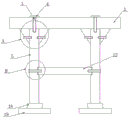
Fig. 1 is a schematic view of the overall structure of the present invention.
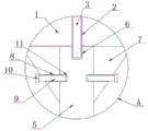
FIG. 2 is an enlarged view of the portion A of FIG. 1 according to the present invention.
FIG. 3 is an enlarged view of the portion B of FIG. 1 according to the present invention.
The reference signs are: the support structure comprises a cross beam 1, a first screw hole 2, a first bolt 3, a first knob 4, a column 5, a second screw hole 6, a support block 7, a third screw hole 8, a second bolt 9, a second knob 10, a fourth screw hole 11, a cross beam 12, a limiting groove 13, a fifth screw hole 14, a third bolt 15, a third knob 16, a sixth screw hole 17, a first cushion block 18 and a second cushion block 19.
Detailed Description
The technical solutions in the embodiments of the present invention will be clearly and completely described below with reference to the drawings in the embodiments of the present invention, and it is obvious that the described embodiments are only a part of the embodiments of the present invention, and not all of the embodiments. All other embodiments, which can be derived by a person skilled in the art from the embodiments given herein without making any creative effort, shall fall within the protection scope of the present invention.
A steel structure net rack shown in figures 1-3 comprises a cross beam 1, wherein the top end surface of the cross beam 1 is provided with a plurality of first screw holes 2, the plurality of first screw holes 2 are uniformly distributed at the top end of the cross beam 1, the inner side of each first screw hole 2 is provided with a first bolt 3, the inner side of each first screw hole 2 is in threaded connection with a bolt, the top end of each first bolt 3 is fixedly connected with a first knob 4, the bottom end of the cross beam 1 is provided with a stand column 5, the plurality of stand columns 5 are uniformly distributed at the bottom end of the cross beam 1, the top end surface of each stand column 5 is provided with a second screw hole 6, each second screw hole 6 is arranged at the bottom end of the corresponding first screw hole 2, the inner side of each second screw hole 6 is in threaded connection with the bottom end of the corresponding first bolt 3, two sides of each stand column 5 are provided with supporting blocks 7, one side of the supporting block 7 is attached to the surface of the upright post 5, the top end of the supporting block 7 is attached to the cross beam 1, a third screw hole 8 is formed in the surface of one side of the supporting block 7, which is far away from the upright post 5, a second bolt 9 is arranged on the inner side of the third screw hole 8, the inner side of the third screw hole 8 is in threaded connection with the second bolt 9, one end of the second bolt 9 is fixedly connected with a second knob 10, a fourth screw hole 11 is formed in the surface of the top end of the upright post 5, the number of the fourth screw holes 11 is two, two fourth screw holes 11 are distributed on two sides of the top end of the upright post 5, the fourth screw holes 11 are matched with the third screw holes 8, the inner side of the fourth screw holes 11 is in threaded connection with the second bolt 9, a cross rod 12 is arranged between the two upright posts 5, a limiting groove 13 is formed in the surface of one, a third bolt 15 is in threaded connection with the inner side of the screw hole, a third knob 16 is fixedly connected to one end of the third bolt 15, a sixth screw hole 17 is formed in the surface of one end of the cross rod 12, the sixth screw hole 17 is matched with the fifth screw hole 14, and the inner side of the sixth screw hole 17 is in threaded connection with the third bolt 15;
furthermore, the two supporting blocks 7 are symmetrically distributed about the upright post 5;
further, a first cushion block 18 is arranged at the bottom end of the upright post 5, the top end of the first cushion block 18 is fixedly connected with the upright post 5, a second cushion block 19 is arranged at the bottom end of the first cushion block 18, and the bottom end of the first cushion block 18 is fixedly connected with the second cushion block 19;
further, the second head block 19 has a length larger than that of the first head block 18.
The working principle of the invention is as follows:
referring to the attached drawings 1-3 of the specification, the upright post 5 and the cross beam 1 are convenient to detach by arranging the first bolt 3 and the second bolt 9, and the working efficiency is greatly improved.
The points to be finally explained are: first, in the description of the present application, it should be noted that, unless otherwise specified and limited, the terms "mounted," "connected," and "connected" should be understood broadly, and may be a mechanical connection or an electrical connection, or a communication between two elements, and may be a direct connection, and "upper," "lower," "left," and "right" are only used to indicate a relative positional relationship, and when the absolute position of the object to be described is changed, the relative positional relationship may be changed;
secondly, the method comprises the following steps: in the drawings of the disclosed embodiments of the invention, only the structures related to the disclosed embodiments are referred to, other structures can refer to common designs, and the same embodiment and different embodiments of the invention can be combined with each other without conflict;
and finally: the above description is only for the purpose of illustrating the preferred embodiments of the present invention and is not to be construed as limiting the invention, and any modifications, equivalents, improvements and the like that are within the spirit and principle of the present invention are intended to be included in the scope of the present invention.
Claims (4)
1. The utility model provides a steel structure net rack, includes crossbeam (1), its characterized in that: the top end surface of the crossbeam (1) is provided with a plurality of first screw holes (2), the first screw holes (2) are uniformly distributed at the top end of the crossbeam (1), the inner side of each first screw hole (2) is provided with a first bolt (3), the inner side of each first screw hole (2) is in threaded connection with a bolt, the top end of each first bolt (3) is fixedly connected with a first knob (4), the bottom end of the crossbeam (1) is provided with a plurality of upright columns (5), the upright columns (5) are uniformly distributed at the bottom end of the crossbeam (1), the top end surface of each upright column (5) is provided with a second screw hole (6), the second screw hole (6) is arranged at the bottom end of each first screw hole (2), the second screw holes (6) are matched with the first screw holes (2), and the inner side of each second screw hole (6) is in threaded connection with the bottom ends of the first bolts (3), the supporting blocks (7) are arranged on two sides of the upright post (5), one side of each supporting block (7) is attached to the surface of the upright post (5), the top end of each supporting block (7) is attached to the cross beam (1), a third screw hole (8) is formed in the surface of one side, far away from the upright post (5), of each supporting block (7), a second bolt (9) is arranged on the inner side of each third screw hole (8), the inner side of each third screw hole (8) is in threaded connection with the corresponding second bolt (9), one end of each second bolt (9) is fixedly connected with a second knob (10), fourth screw holes (11) are formed in the surface of the top end of the upright post (5), the number of the fourth screw holes (11) is two, the two fourth screw holes (11) are distributed on two sides of the top end of the upright post (5), the fourth screw holes (11) are matched with the third screw holes (8), and the inner side of each, two be equipped with horizontal pole (12) between stand (5), spacing groove (13) have been seted up on stand (5) side surface, horizontal pole (12) one end matches with spacing groove (13), fifth screw (14) have been seted up on stand (5) side surface, the inboard threaded connection of screw has third bolt (15), third bolt (15) one end fixedly connected with third knob (16), sixth screw (17) have been seted up on horizontal pole (12) one end surface, sixth screw (17) match with fifth screw (14), sixth screw (17) inboard and third bolt (15) threaded connection.
2. A steel structural grid according to claim 1, wherein: the two supporting blocks (7) are symmetrically distributed around the upright post (5).
3. A steel structural grid according to claim 1, wherein: the novel vertical column structure is characterized in that a first cushion block (18) is arranged at the bottom end of the vertical column (5), the top end of the first cushion block (18) is fixedly connected with the vertical column (5), a second cushion block (19) is arranged at the bottom end of the first cushion block (18), and the bottom end of the first cushion block (18) is fixedly connected with the second cushion block (19).
4. A steel structural grid according to claim 1, wherein: the second pad (19) has a greater length than the first pad (18).
Priority Applications (1)
| Application Number | Priority Date | Filing Date | Title |
|---|---|---|---|
| CN201911078052.XA CN110748001A (en) | 2019-11-06 | 2019-11-06 | Steel structure net rack |
Applications Claiming Priority (1)
| Application Number | Priority Date | Filing Date | Title |
|---|---|---|---|
| CN201911078052.XA CN110748001A (en) | 2019-11-06 | 2019-11-06 | Steel structure net rack |
Publications (1)
| Publication Number | Publication Date |
|---|---|
| CN110748001A true CN110748001A (en) | 2020-02-04 |
Family
ID=69282449
Family Applications (1)
| Application Number | Title | Priority Date | Filing Date |
|---|---|---|---|
| CN201911078052.XA Pending CN110748001A (en) | 2019-11-06 | 2019-11-06 | Steel structure net rack |
Country Status (1)
| Country | Link |
|---|---|
| CN (1) | CN110748001A (en) |
Cited By (2)
| Publication number | Priority date | Publication date | Assignee | Title |
|---|---|---|---|---|
| CN111636583A (en) * | 2020-06-19 | 2020-09-08 | 滕信虎 | Steel structure system |
| CN113404165A (en) * | 2021-06-29 | 2021-09-17 | 长沙三远钢结构有限公司 | Assembled steel-concrete composite structure and manufacturing method thereof |
Citations (2)
| Publication number | Priority date | Publication date | Assignee | Title |
|---|---|---|---|---|
| CN207392708U (en) * | 2017-10-25 | 2018-05-22 | 江苏南通二建集团有限公司 | A kind of Fast Installation scaffold for building |
| CN209144993U (en) * | 2018-09-06 | 2019-07-23 | 苏州古镇联盟建筑设计有限公司 | A kind of Prestressed Space network |
-
2019
- 2019-11-06 CN CN201911078052.XA patent/CN110748001A/en active Pending
Patent Citations (2)
| Publication number | Priority date | Publication date | Assignee | Title |
|---|---|---|---|---|
| CN207392708U (en) * | 2017-10-25 | 2018-05-22 | 江苏南通二建集团有限公司 | A kind of Fast Installation scaffold for building |
| CN209144993U (en) * | 2018-09-06 | 2019-07-23 | 苏州古镇联盟建筑设计有限公司 | A kind of Prestressed Space network |
Cited By (3)
| Publication number | Priority date | Publication date | Assignee | Title |
|---|---|---|---|---|
| CN111636583A (en) * | 2020-06-19 | 2020-09-08 | 滕信虎 | Steel structure system |
| CN111636583B (en) * | 2020-06-19 | 2021-11-23 | 中建二局第一建筑工程有限公司 | Steel structure system |
| CN113404165A (en) * | 2021-06-29 | 2021-09-17 | 长沙三远钢结构有限公司 | Assembled steel-concrete composite structure and manufacturing method thereof |
Similar Documents
| Publication | Publication Date | Title |
|---|---|---|
| CN201771197U (en) | Assembly jig frame with function of elevation adjustment | |
| CN110748001A (en) | Steel structure net rack | |
| CN203583974U (en) | 750KV outdoor A-shaped column, lattice type column and power distribution device | |
| CN201486148U (en) | Assembled processing shed | |
| CN104695605A (en) | Assembling type die of rib floor | |
| CN209741895U (en) | Connection structure of assembled elevator steel construction and base | |
| CN201924284U (en) | Screw rod seat pipe double-split Bailey bracket | |
| CN102864746A (en) | Bearing frame for bridge construction | |
| CN107447863B (en) | Cantilever structure for steel structure factory building | |
| CN106351429A (en) | Heavy support system and construction method thereof | |
| CN110748012A (en) | Steel structure crossbeam | |
| CN206428986U (en) | A kind of detachable turnover type support jig | |
| CN103397638A (en) | Tie bar for supporting system in high-rigidity integral prestressed fabricated foundation pit support | |
| CN204645668U (en) | The top support structure of shape steel support installed by a kind of rack | |
| CN203225074U (en) | Advertising board of net rack structure | |
| CN208650875U (en) | A kind of vault crossbeam of steel construction | |
| CN218114844U (en) | Tower crane crossover sub | |
| CN220685792U (en) | Adjustable temporary supporting device | |
| CN203271193U (en) | Large overhang stand with space structure | |
| CN212223631U (en) | Steel anchor beam fine tuning auxiliary operation platform | |
| CN216787928U (en) | Supporting system for assembling precast concrete | |
| CN215978620U (en) | Assembled stair for foundation pit construction | |
| CN220225934U (en) | Steel-concrete connection structure for constructional engineering | |
| CN205224579U (en) | Steel framework template and self -supporting truss board combination concrete quick detach system | |
| CN203878739U (en) | Lightweight steel structure building system |
Legal Events
| Date | Code | Title | Description |
|---|---|---|---|
| PB01 | Publication | ||
| PB01 | Publication | ||
| SE01 | Entry into force of request for substantive examination | ||
| SE01 | Entry into force of request for substantive examination | ||
| WD01 | Invention patent application deemed withdrawn after publication |
Application publication date: 20200204 |
|
| WD01 | Invention patent application deemed withdrawn after publication |