CN110741502B - Gas measuring apparatus for secondary battery - Google Patents
Gas measuring apparatus for secondary battery Download PDFInfo
- Publication number
- CN110741502B CN110741502B CN201880039118.1A CN201880039118A CN110741502B CN 110741502 B CN110741502 B CN 110741502B CN 201880039118 A CN201880039118 A CN 201880039118A CN 110741502 B CN110741502 B CN 110741502B
- Authority
- CN
- China
- Prior art keywords
- gas
- secondary battery
- chamber
- gas measurement
- sealing member
- Prior art date
- Legal status (The legal status is an assumption and is not a legal conclusion. Google has not performed a legal analysis and makes no representation as to the accuracy of the status listed.)
- Active
Links
Images


Classifications
-
- G—PHYSICS
- G01—MEASURING; TESTING
- G01N—INVESTIGATING OR ANALYSING MATERIALS BY DETERMINING THEIR CHEMICAL OR PHYSICAL PROPERTIES
- G01N1/00—Sampling; Preparing specimens for investigation
- G01N1/02—Devices for withdrawing samples
- G01N1/22—Devices for withdrawing samples in the gaseous state
- G01N1/2226—Sampling from a closed space, e.g. food package, head space
-
- H—ELECTRICITY
- H01—ELECTRIC ELEMENTS
- H01M—PROCESSES OR MEANS, e.g. BATTERIES, FOR THE DIRECT CONVERSION OF CHEMICAL ENERGY INTO ELECTRICAL ENERGY
- H01M10/00—Secondary cells; Manufacture thereof
- H01M10/60—Heating or cooling; Temperature control
- H01M10/61—Types of temperature control
- H01M10/615—Heating or keeping warm
-
- H—ELECTRICITY
- H01—ELECTRIC ELEMENTS
- H01M—PROCESSES OR MEANS, e.g. BATTERIES, FOR THE DIRECT CONVERSION OF CHEMICAL ENERGY INTO ELECTRICAL ENERGY
- H01M10/00—Secondary cells; Manufacture thereof
- H01M10/42—Methods or arrangements for servicing or maintenance of secondary cells or secondary half-cells
- H01M10/4285—Testing apparatus
-
- G—PHYSICS
- G01—MEASURING; TESTING
- G01D—MEASURING NOT SPECIALLY ADAPTED FOR A SPECIFIC VARIABLE; ARRANGEMENTS FOR MEASURING TWO OR MORE VARIABLES NOT COVERED IN A SINGLE OTHER SUBCLASS; TARIFF METERING APPARATUS; MEASURING OR TESTING NOT OTHERWISE PROVIDED FOR
- G01D21/00—Measuring or testing not otherwise provided for
- G01D21/02—Measuring two or more variables by means not covered by a single other subclass
-
- G—PHYSICS
- G01—MEASURING; TESTING
- G01N—INVESTIGATING OR ANALYSING MATERIALS BY DETERMINING THEIR CHEMICAL OR PHYSICAL PROPERTIES
- G01N1/00—Sampling; Preparing specimens for investigation
- G01N1/02—Devices for withdrawing samples
- G01N1/22—Devices for withdrawing samples in the gaseous state
- G01N1/24—Suction devices
-
- G—PHYSICS
- G01—MEASURING; TESTING
- G01N—INVESTIGATING OR ANALYSING MATERIALS BY DETERMINING THEIR CHEMICAL OR PHYSICAL PROPERTIES
- G01N25/00—Investigating or analyzing materials by the use of thermal means
- G01N25/20—Investigating or analyzing materials by the use of thermal means by investigating the development of heat, i.e. calorimetry, e.g. by measuring specific heat, by measuring thermal conductivity
- G01N25/22—Investigating or analyzing materials by the use of thermal means by investigating the development of heat, i.e. calorimetry, e.g. by measuring specific heat, by measuring thermal conductivity on combustion or catalytic oxidation, e.g. of components of gas mixtures
- G01N25/28—Investigating or analyzing materials by the use of thermal means by investigating the development of heat, i.e. calorimetry, e.g. by measuring specific heat, by measuring thermal conductivity on combustion or catalytic oxidation, e.g. of components of gas mixtures the rise in temperature of the gases resulting from combustion being measured directly
-
- G—PHYSICS
- G01—MEASURING; TESTING
- G01N—INVESTIGATING OR ANALYSING MATERIALS BY DETERMINING THEIR CHEMICAL OR PHYSICAL PROPERTIES
- G01N33/00—Investigating or analysing materials by specific methods not covered by groups G01N1/00 - G01N31/00
- G01N33/0004—Gaseous mixtures, e.g. polluted air
- G01N33/0009—General constructional details of gas analysers, e.g. portable test equipment
- G01N33/0027—General constructional details of gas analysers, e.g. portable test equipment concerning the detector
-
- G—PHYSICS
- G01—MEASURING; TESTING
- G01N—INVESTIGATING OR ANALYSING MATERIALS BY DETERMINING THEIR CHEMICAL OR PHYSICAL PROPERTIES
- G01N7/00—Analysing materials by measuring the pressure or volume of a gas or vapour
- G01N7/14—Analysing materials by measuring the pressure or volume of a gas or vapour by allowing the material to emit a gas or vapour, e.g. water vapour, and measuring a pressure or volume difference
-
- H—ELECTRICITY
- H01—ELECTRIC ELEMENTS
- H01M—PROCESSES OR MEANS, e.g. BATTERIES, FOR THE DIRECT CONVERSION OF CHEMICAL ENERGY INTO ELECTRICAL ENERGY
- H01M10/00—Secondary cells; Manufacture thereof
- H01M10/42—Methods or arrangements for servicing or maintenance of secondary cells or secondary half-cells
- H01M10/48—Accumulators combined with arrangements for measuring, testing or indicating the condition of cells, e.g. the level or density of the electrolyte
- H01M10/486—Accumulators combined with arrangements for measuring, testing or indicating the condition of cells, e.g. the level or density of the electrolyte for measuring temperature
-
- G—PHYSICS
- G01—MEASURING; TESTING
- G01N—INVESTIGATING OR ANALYSING MATERIALS BY DETERMINING THEIR CHEMICAL OR PHYSICAL PROPERTIES
- G01N1/00—Sampling; Preparing specimens for investigation
- G01N1/02—Devices for withdrawing samples
- G01N1/22—Devices for withdrawing samples in the gaseous state
- G01N1/24—Suction devices
- G01N2001/248—Evacuated containers
-
- G—PHYSICS
- G01—MEASURING; TESTING
- G01N—INVESTIGATING OR ANALYSING MATERIALS BY DETERMINING THEIR CHEMICAL OR PHYSICAL PROPERTIES
- G01N31/00—Investigating or analysing non-biological materials by the use of the chemical methods specified in the subgroup; Apparatus specially adapted for such methods
- G01N31/12—Investigating or analysing non-biological materials by the use of the chemical methods specified in the subgroup; Apparatus specially adapted for such methods using combustion
-
- Y—GENERAL TAGGING OF NEW TECHNOLOGICAL DEVELOPMENTS; GENERAL TAGGING OF CROSS-SECTIONAL TECHNOLOGIES SPANNING OVER SEVERAL SECTIONS OF THE IPC; TECHNICAL SUBJECTS COVERED BY FORMER USPC CROSS-REFERENCE ART COLLECTIONS [XRACs] AND DIGESTS
- Y02—TECHNOLOGIES OR APPLICATIONS FOR MITIGATION OR ADAPTATION AGAINST CLIMATE CHANGE
- Y02E—REDUCTION OF GREENHOUSE GAS [GHG] EMISSIONS, RELATED TO ENERGY GENERATION, TRANSMISSION OR DISTRIBUTION
- Y02E60/00—Enabling technologies; Technologies with a potential or indirect contribution to GHG emissions mitigation
- Y02E60/10—Energy storage using batteries
Abstract
A gas measurement device for a secondary battery includes: a chamber accommodating a secondary battery therein; a heater unit applying heat to the chamber to ignite the secondary battery contained in the chamber; a collecting pipe connected to an inside of the chamber to collect gas generated in the secondary battery; a vacuum unit connected to the collection pipe to vacuumize the inside of the chamber, thereby introducing gas into the collection pipe; and a gas measuring unit that measures the amount of gas introduced into the collecting pipe.
Description
Technical Field
Cross Reference to Related Applications
This application claims priority from korean patent application No. 10-2017-0117886, filed on 9/14/2017, which is hereby incorporated by reference in its entirety.
Technical Field
The present invention relates to a gas measuring apparatus for a secondary battery.
Background
Unlike primary batteries, rechargeable batteries are rechargeable and are highly likely to be compact in size and high in capacity. Therefore, recently, many studies on rechargeable batteries are underway. As the technical development and demand for mobile devices increases, the demand for rechargeable batteries as an energy source is rapidly increasing.
The rechargeable battery is classified into a coin type battery, a cylindrical type battery, a prismatic type battery, and a pouch type battery according to the shape of a battery case. In such a secondary battery, an electrode assembly mounted in a battery case is a chargeable and dischargeable power generation device having a structure in which electrodes and separators are stacked.
The electrode assembly may be broadly divided into: a Jelly-roll (Jelly-roll) type electrode assembly in which a separator is interposed between a positive electrode and a negative electrode, each of which is provided in the form of a sheet coated with an active material, and then the positive electrode, the separator, and the negative electrode are wound; a stacking type electrode assembly in which a plurality of positive electrodes and negative electrodes are sequentially stacked with separators interposed therebetween; and a stacking/folding type electrode assembly in which a stacking type unit cell is wound together with a separation film having a long length.
The stability of the secondary battery is important, and it is necessary to analyze the amount of gas and harmful components generated when the secondary battery is ignited.
Disclosure of Invention
Technical problem
An aspect of the present invention is to provide a gas measuring apparatus for a secondary battery, which is capable of easily collecting and analyzing the amount and harmful components of gas generated when the secondary battery is ignited.
Technical scheme
A gas measurement apparatus for a secondary battery may include: a chamber accommodating a secondary battery therein; a heater unit that applies heat to the chamber to ignite the secondary battery contained in the chamber; a collecting pipe connected to an inside of the chamber to collect gas generated in the secondary battery; a vacuum unit connected to the collection pipe to vacuumize the inside of the chamber, thereby introducing gas into the collection pipe; and a gas measuring unit that measures the amount of gas introduced into the collecting pipe.
Advantageous effects
According to the present invention, the amount of gas and harmful components generated when the secondary battery fires can be analyzed by firing the secondary battery.
Further, according to the present invention, it is possible to simply and easily perform Sampling (Sampling) of gas generated when the secondary battery is ignited by heating the chamber using the heater unit to ignite the secondary battery, and the collecting pipe may be connected to the chamber to collect the gas generated when the secondary battery is ignited.
Further, according to the present invention, a cooling device may be provided to maintain the sealability of the chamber in which the secondary battery is accommodated. That is, the sealing member disposed on the portion of the sealing chamber may be cooled via a cooling device to prevent the sealing member having an O-ring (Oring) shape from being thermally damaged. Therefore, the sealability of the chamber may be maintained when the secondary battery is ignited, the ignition gas within the secondary battery contained in the chamber may be easily collected, and the harmful gas may be prevented from being discharged to the outside, thereby improving stability.
Further, according to the present invention, the heater unit and the chamber may be accommodated in a holder made of a heat-resistant material and a high-strength material to isolate risk factors generated when the secondary battery is ignited from the outside, thereby improving stability.
Drawings
Fig. 1 is a front view of a gas measurement device for a secondary battery according to an embodiment of the present invention.
Fig. 2 is a perspective view of a gas measurement apparatus for a secondary battery according to an embodiment of the present invention.
Fig. 3 isbase:Sub>A sectional view taken along linebase:Sub>A-base:Sub>A' in fig. 2.
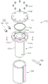
Fig. 4 is an exploded perspective view of a chamber and a heater unit in a gas measuring apparatus for a secondary battery according to an embodiment of the present invention.
Fig. 5 is a sectional view taken along line B-B' in fig. 4.
Fig. 6 is a perspective view of a gas measurement apparatus for a secondary battery according to another embodiment of the present invention.
Fig. 7 is a perspective view of a holder in a gas measurement device for a secondary battery according to another embodiment of the present invention.
Fig. 8 is an exploded perspective view of a holder, a chamber, and a heater unit in a gas measuring apparatus for a secondary battery according to another embodiment of the present invention.
Detailed Description
The objects, specific advantages and novel features of the invention will become more apparent from the following detailed description of the invention when taken in conjunction with the drawings. It should be noted that in the present specification, components in the drawings are denoted by the same reference numerals as much as possible even if the components are shown in other drawings. Furthermore, the present invention may be embodied in different forms and should not be construed as limited to the embodiments set forth herein. In the following description of the present invention, a detailed description of related art that may unnecessarily obscure the gist of the present invention will be omitted.
Fig. 1 isbase:Sub>A front view ofbase:Sub>A gas measuring apparatus forbase:Sub>A secondary battery according to an embodiment of the present invention, fig. 2 isbase:Sub>A perspective view of the gas measuring apparatus forbase:Sub>A secondary battery according to an embodiment of the present invention, and fig. 3 isbase:Sub>A sectional view taken along linebase:Sub>A-base:Sub>A' in fig. 2.
Referring to fig. 1 to 3, a gas measurement apparatus 100 for a secondary battery according to an embodiment of the present invention includes: a Chamber (Chamber) 110 that accommodates the secondary battery 10; a heater unit 120 that applies heat to the secondary battery 10 to ignite the secondary battery 10; a collecting pipe 130 for collecting gas; a vacuum unit 140 for evacuating the chamber 110; a gas measuring unit 150 that measures the amount of gas.
Hereinafter, a gas measuring apparatus for a secondary battery according to an embodiment of the present invention will be described in detail with reference to fig. 1 to 5.
Fig. 4 is an exploded perspective view of a chamber and a heater unit in a gas measuring apparatus for a secondary battery according to an embodiment of the present invention, and fig. 5 is a sectional view taken along line B-B' in fig. 4.
Referring to fig. 3 and 4, the chamber 110 includes an accommodating part 111a for accommodating the secondary battery 10.
For example, the secondary battery 10 may include a battery case 11 and an electrode assembly 12 accommodated in the battery case 11. Here, the electrode assembly 12 may be a chargeable and dischargeable power generation element, and have a structure in which electrodes 12c and separators 12d are combined and alternately stacked. The electrodes 12c may include a positive electrode 12a and a negative electrode 12b. In addition, the electrode assembly 12 may have a structure in which the positive electrodes 12 a/the separators 12 d/the negative electrodes 12b are alternately stacked.
The chamber 110 may include a body 111 and a cover 112, the body 111 including an accommodating part 111a having one open side to accommodate the secondary battery 10, and the cover 112 covering one side of the body 111 to seal the accommodating part 111a. Here, each of the body 111 and the cover 112 may be made of, for example, stainless steel. Specifically, each of the body 111 and the cover 112 may be made of a sus-316 material, for example.
In addition, the chamber 110 may further include: a sealing member 114 sealing a gap between the body 111 and the cover 112, and a cooling device 117 cooling the sealing member 114 to prevent the sealing member 114 from being thermally damaged.
The main body 111 includes an accommodating portion 111a having one open side to accommodate the secondary battery 10.
Further, an accommodation groove 111d accommodating the sealing member 114 may be formed at an end of the body 111. Here, the receiving groove 111d may be formed in a circular shape in an end surface of the main body 111 on a side facing the cover 112.
In addition, the main body 111 may include a receiving body receiving the secondary battery 10 and a coupling portion 111c providing a coupling portion to which the cover 112 is coupled by a coupling device 113.
The accommodating body 111b may have a cylindrical shape opened upward. Here, the receiving body 111b may have a cylindrical receiving space opened upward to receive, for example, the cylindrical secondary battery 10. Further, a collection hole 111f through which the collection tube 130 passes is formed in the accommodating body 111b such that one side of the collection tube 130 is inserted into the collection hole 111 f.
The coupling part 111c may be disposed above the accommodating body 111b and have an accommodating groove 111d in a top surface thereof. Here, the receiving groove 111d may have a circular shape larger than the receiving space of the receiving body 111 b. Here, the accommodation groove 111d may be opened in the direction of the cover 112 and have a shape into which a circular ring is inserted.
In addition, the coupling portion 111c may be spaced apart from the receiving groove 111d by a predetermined distance on a plane to form a plurality of coupling holes 111e to which the coupling device 113 is coupled.
The cover 112 may cover one side of the body 111 to seal the receiving portion 111a formed in the body 111. Here, the cover 112 may cover a top surface of the coupling portion 111c of the body 111 to seal the receiving space formed in the receiving body 111 b.
Further, the cover 112 may be fixed to the body 111 by a coupling device 113. Here, the cover 112 may have a through hole 112e, and the coupling device 113 is coupled to the through hole 112e. Here, the coupling means 113 may be provided as, for example, a screw, and a threaded portion may be formed on an inner circumferential surface of the through hole 112e so that the screw passes through for coupling.
A sealing member 114 may be disposed between the body 111 and the cover 112 to seal a gap between the body 111 and the cover 112.
In addition, the sealing member 114 may be received in a receiving groove 111d formed in the body 111 of the chamber 110.
Further, the sealing member 114 may have a lower portion closely attached to the bottom surface of the receiving groove 111d and an upper portion closely attached to the bottom surface of the cover 112.
Further, the sealing member 114 may be made of a flexible heat-resistant material. Here, the height of the sealing member may be equal to or greater than the height of the accommodation groove 111d. Further, the sealing member 114 may be made of, for example, synthetic resin, synthetic plastic, or synthetic rubber. Here, the sealing member 114 may be made of, for example, silicon gel (Silcon).
The sealing member 114 may be provided, for example, as an O-ring (Oring).
Referring to fig. 3 to 5, the cooling device 117 may cool the sealing member 114 so that the sealing member 114 is not thermally damaged.
Further, the cooling device 117 may include an inlet nozzle through which the coolant W is introduced into the receiving groove 111d of the body 111, and an outlet nozzle 116 through which the coolant W is discharged from the receiving groove 111d. Here, the cooling device 117 may introduce the coolant W through the inlet nozzle 115, and the coolant W introduced into the accommodation groove 111d may move along the accommodation groove 111d to cool the sealing member disposed in the accommodation groove 111d and then be discharged from the accommodation groove 111d through the outlet nozzle 116.
Further, the angle α between the inlet nozzle 115 and the outlet nozzle 116 connected to the accommodation groove 111d with respect to the center of the circle drawn by the accommodation groove 111d may be less than, for example, 45 °. Specifically, the angle α between the inlet nozzle 115 and the outlet nozzle 116 may be, for example, 5 ° to 45 °.
Therefore, when the coolant introduced through the inlet nozzle 115 moves along the receiving groove 111d to cool the sealing member 114 and then is discharged through the outlet nozzle 116, the coolant may contact the sealing member 114 having a large area to effectively cool the sealing member 114.
A Heater (Heater) unit may apply heat to the chamber 110 to ignite the secondary battery 10 received in the chamber 110.
In addition, the heater unit 120 may have a cylindrical shape to surround the outer circumferential surface of the body 111 of the chamber 110.
In addition, the heater unit 120 may include a heating coil to transfer resistance heat of the heating coil to the main body 111 of the chamber 110, thereby igniting the secondary battery 10.
Here, the heater unit 120 may apply heat having a temperature of, for example, about 600 degrees or more to the secondary battery 10 to ignite the secondary battery 10.
Referring to fig. 2 and 3, a collecting pipe 130 may be connected to the inside of the chamber 110 to collect gas generated in the secondary battery 10.
In addition, the collecting pipe 130 may further include a Gas Tank (Gas Tank) 132 that provides a space for accommodating the collected Gas.
Further, the collecting pipe 130 may have, for example, one side connected to the chamber 110 and the other side connected to the gas tank 132.
In addition, the collection pipe 130 may further include a collection valve 131 disposed between the chamber 110 and the gas tank 132 to open and close the collection pipe 130.
A vacuum unit 140 may be connected to the collecting duct 130 to vacuumize the inside of the chamber 110 such that gas generated when the secondary battery 10 is ignited is introduced into the collecting duct 130.
Further, the vacuum unit 140 may include: a vacuum tube 142, one side of the vacuum tube 142 being connected to the collection tube 130; a vacuum pump 141 connected to the other side of the vacuum pipe 142; and a vacuum valve 143 that opens and closes the vacuum tube 142. Here, a vacuum tube 142 may be connected between the chamber 110 and the gas tank 132 of the collection tube 130. Specifically, the vacuum tube 142 may be connected to a portion of the collection tube 130 disposed between the collection valve 131 of the collection tube 130 and the gas tank 132.
Further, the Vacuum pump may be, for example, a Rotary Vacuum pump (Rotary Vacuum pump), and may apply a Vacuum of about 200 liters per minute (liter/min).
In addition, the gas measuring unit 150 may include a pressure gauge 151 that measures the amount of gas generated and a temperature sensor 152 that measures the temperature of the gas.
A pressure Gauge (Gauge) 151 may measure the pressure of the gas introduced into the collection pipe 130. Therefore, the amount of gas generated in the secondary battery 10 can be measured by the measured gas pressure. Here, a metering valve 151a may be further provided between the collection tube 130 and the pressure gauge 151 to restrict opening and closing between the collection tube 130 and the pressure gauge 151.
The pressure gauge 151 may measure the pressure of the gas contained in the gas tank 132, and the temperature sensor 152 may measure the temperature of the gas contained in the gas tank 132.
Fig. 6 is a perspective view of a gas measurement apparatus for a secondary battery according to another embodiment of the present invention.
Referring to fig. 6, a gas measurement apparatus 200 for a secondary battery according to another embodiment of the present invention includes: a chamber 110 accommodating the secondary battery 10; a heater unit 120 that applies heat to the secondary battery 10 to ignite the secondary battery 10; a collecting pipe 130 for collecting gas; a vacuum unit 140 for evacuating the chamber 110; a gas measuring unit 250 that measures the amount of gas. (see FIG. 3).
The gas measurement apparatus 200 for a secondary battery according to another embodiment of the present invention is different from the gas measurement apparatus 100 for a secondary battery according to the foregoing embodiment of the present invention in that: the gas measurement apparatus 200 further includes: a holder 260 accommodating the heater unit 120 and the chamber 110, and a gas analysis portion 253 analyzing gas components. Therefore, the contents of this embodiment and those of repetition according to the foregoing embodiment will be briefly described, and further, the differences therebetween will be mainly described.
Fig. 7 is a perspective view of a holder in a gas measuring apparatus for a secondary battery according to another embodiment of the present invention, and fig. 8 is an exploded perspective view of the holder, a chamber, and a heater unit in a gas measuring apparatus for a secondary battery according to another embodiment of the present invention.
In detail, referring to fig. 6 to 8, in a gas measuring apparatus 200 for a secondary battery according to another embodiment of the present invention, a holder 260 may receive therein a heater unit 120 and a chamber 110 to isolate risk factors generated when the secondary battery fires from the outside.
Further, the holder 260 may include a first holder 261 and a second holder 262.
Further, the holder 260 may include a heat-resistant material and a high-strength material.
In the gas measuring apparatus 200 for a secondary battery according to another embodiment of the present invention, the gas measuring unit 250 may include: a pressure gauge 251 that measures the amount of gas generated; a gas analyzer 253 for analyzing gas components; and a temperature sensor 252 that measures the temperature of the gas.
The pressure gauge 251 may measure the pressure of the gas introduced into the collecting pipe 130 to extract the amount of the gas generated in the secondary battery. Here, a metering valve 251a may be further provided between the collection pipe 130 and the pressure gauge 251 to restrict opening and closing between the collection pipe 130 and the pressure gauge 251.
The pressure gauge 251 may measure the pressure of the gas contained in the gas tank 132 of the collecting pipe 130, and the temperature sensor 252 may measure the temperature of the gas contained in the gas tank 132.
The gas analysis part 253 may analyze the composition of the gas introduced into the collecting pipe 130 to analyze whether the gas contains a harmful component to analyze the harmful component. Here, the Gas analyzer 253 may include, for example, a Gas chromatograph (Gas chromatography).
Further, a gas analysis portion 253 may be connected to the gas tank 132 of the collection pipe 130 to analyze the composition of the gas contained in the gas tank 132. Here, a throttle valve 253a may be provided between the gas analysis portion 253 and the gas tank 132 to restrict opening and closing between the gas tank 132 and the gas analysis portion 253.
While the present invention has been particularly shown and described with reference to exemplary embodiments thereof, it will be understood that the scope of the invention is not limited to the gas measurement device for a secondary battery according to the present invention. It will be understood by those of ordinary skill in the art that various changes in form and details may be made therein without departing from the spirit and scope of the present invention.
Furthermore, the scope of the invention is to be construed in accordance with the substance defined by the following claims.
Claims (10)
1. A gas measurement apparatus for a secondary battery, the gas measurement apparatus comprising:
a chamber accommodating a secondary battery therein;
a heater unit that applies heat to the chamber to ignite the secondary battery contained in the chamber;
a collecting pipe connected to an inside of the chamber to collect gas generated in the secondary battery;
a vacuum unit connected to the collection tube to vacuumize the inside of the chamber, thereby introducing gas into the collection tube; and
a gas measuring unit that measures an amount of gas introduced into the collecting pipe,
wherein the chamber comprises:
a main body including a receiving part having one side opened to receive the secondary battery;
a cover covering one side of the main body to seal the receiving part;
a sealing member disposed between the body and the cover to seal a gap between the body and the cover; and
a cooling device that cools the sealing member to prevent the sealing member from being thermally damaged,
wherein the body has an end portion in which a receiving groove for receiving the sealing member is formed,
wherein the cooling device comprises:
an inlet nozzle through which coolant is introduced into the receiving tank; and
an outlet nozzle through which coolant is discharged from the receiving tank,
wherein the coolant introduced into the receiving groove through the inlet nozzle moves along the receiving groove to cool the sealing member disposed in the receiving groove and is then discharged from the receiving groove through the outlet nozzle.
2. The gas measurement apparatus according to claim 1, wherein the heater unit includes a heating coil having a cylindrical shape to surround an outer circumferential surface of the main body of the chamber, and transfers resistive heat of the heating coil to the main body of the chamber to ignite the secondary battery.
3. The gas measurement device according to claim 1, wherein the accommodation groove is open in a direction of the cover and has a shape into which a circular ring is insertable,
the sealing member includes an O-ring (Oring).
4. The gas measurement device according to claim 3, wherein an angle between the inlet nozzle and the outlet nozzle connected to the receiving tank with respect to a center of a circle drawn by the receiving tank is less than 45 °.
5. The gas measurement device according to claim 1, further comprising a holder that is made of a heat-resistant material and accommodates the heater unit and the chamber therein to isolate a risk factor generated when the secondary battery fires from the outside.
6. The gas measurement apparatus of claim 1, wherein the vacuum unit comprises:
a vacuum tube having one side connected to the collection tube;
a vacuum pump connected to the other side of the vacuum tube; and
a vacuum valve that opens and closes the vacuum tube.
7. The gas measurement apparatus according to claim 1, wherein the gas measurement unit includes a pressure gauge that measures a pressure of the gas introduced into the collection pipe to measure an amount of the gas generated.
8. The gas measurement device according to claim 7, wherein the gas measurement unit further comprises a temperature sensor that measures the temperature of the gas introduced into the collection pipe.
9. The gas measurement device of claim 8, wherein the collection tube further comprises a gas canister providing a space to contain the gas,
the pressure gauge measures a pressure of the gas contained in the gas tank, and the temperature sensor measures a temperature of the gas contained in the gas tank.
10. The gas measurement apparatus according to any one of claims 1 and 7 to 9, wherein the gas measurement unit includes a gas analysis portion that analyzes a composition of the gas introduced into the collection pipe.
Applications Claiming Priority (3)
| Application Number | Priority Date | Filing Date | Title |
|---|---|---|---|
| KR10-2017-0117886 | 2017-09-14 | ||
| KR1020170117886A KR102256488B1 (en) | 2017-09-14 | 2017-09-14 | Gas measuring equipment for rechargeable battery test |
| PCT/KR2018/010745 WO2019054767A1 (en) | 2017-09-14 | 2018-09-13 | Gas measuring device for secondary battery |
Publications (2)
| Publication Number | Publication Date |
|---|---|
| CN110741502A CN110741502A (en) | 2020-01-31 |
| CN110741502B true CN110741502B (en) | 2023-04-04 |
Family
ID=65723728
Family Applications (1)
| Application Number | Title | Priority Date | Filing Date |
|---|---|---|---|
| CN201880039118.1A Active CN110741502B (en) | 2017-09-14 | 2018-09-13 | Gas measuring apparatus for secondary battery |
Country Status (5)
| Country | Link |
|---|---|
| US (1) | US11631911B2 (en) |
| EP (1) | EP3627613B1 (en) |
| KR (1) | KR102256488B1 (en) |
| CN (1) | CN110741502B (en) |
| WO (1) | WO2019054767A1 (en) |
Families Citing this family (4)
| Publication number | Priority date | Publication date | Assignee | Title |
|---|---|---|---|---|
| KR20210152885A (en) | 2020-06-09 | 2021-12-16 | 주식회사 엘지에너지솔루션 | Battery cell volume measuring device and battery cell volume measuring method using same |
| CN113009350B (en) * | 2021-02-24 | 2022-02-11 | 清华大学 | Method for analyzing influence of gas inside battery on thermal runaway and gas sampling device |
| CN113390981A (en) * | 2021-05-24 | 2021-09-14 | 超威电源集团有限公司 | Storage battery gassing test equipment and method |
| KR102390992B1 (en) * | 2021-10-14 | 2022-04-27 | (주)티톱이앤지 | A system of leaking inspection of toxic substance and leaking inspection method of toxic substance using thereof |
Citations (4)
| Publication number | Priority date | Publication date | Assignee | Title |
|---|---|---|---|---|
| US4344479A (en) * | 1978-07-28 | 1982-08-17 | Fuelsaver Company | Process and apparatus utilizing common structure for combustion, gas fixation, or waste heat recovery |
| WO2006096956A1 (en) * | 2005-03-17 | 2006-09-21 | Hydrogenics Corporation | Method, system and apparatus for diagnostic testing of an electrochemical cell stack |
| JP2007171009A (en) * | 2005-12-22 | 2007-07-05 | Japan Automobile Research Inst Inc | Burning test device |
| CN205280628U (en) * | 2015-11-18 | 2016-06-01 | 王建刚 | Visual test analytic system of power battery thermal runaway |
Family Cites Families (32)
| Publication number | Priority date | Publication date | Assignee | Title |
|---|---|---|---|---|
| JPS5151926Y2 (en) * | 1972-01-31 | 1976-12-13 | ||
| SE7909477L (en) | 1979-02-26 | 1980-08-27 | Draegerwerk Ag | GASMETINSTRUMENT |
| JP3042648B2 (en) * | 1992-09-18 | 2000-05-15 | 東京電力株式会社 | Disaster prevention device in sodium-sulfur battery |
| RU2091783C1 (en) | 1993-04-26 | 1997-09-27 | Сергей Иванович Ударцев | Gas-analysis device |
| JP3333591B2 (en) | 1993-06-25 | 2002-10-15 | 株式会社フジクラ | Cooling structure of high temperature container seal |
| JP4671462B2 (en) * | 2000-02-22 | 2011-04-20 | パナソニック株式会社 | Airtight inspection method for nickel metal hydride secondary battery |
| JP4253781B2 (en) | 2000-02-23 | 2009-04-15 | 株式会社京浜理化工業 | Gas detector |
| US7128818B2 (en) | 2002-01-09 | 2006-10-31 | General Electric Company | Method and apparatus for monitoring gases in a combustion system |
| JP3885705B2 (en) * | 2002-10-10 | 2007-02-28 | 株式会社デンソー | Gas concentration detector |
| US20060260713A1 (en) * | 2005-04-22 | 2006-11-23 | Pyszczek Michael F | Method and apparatus for providing a sealed container containing a detectable gas |
| KR100793367B1 (en) | 2006-07-31 | 2008-01-11 | 삼성에스디아이 주식회사 | Heating furnace, heating apparatus including the same and fabricating method of organic light emitting display device using the same |
| JP4862542B2 (en) | 2006-08-02 | 2012-01-25 | 三菱化学株式会社 | Safety evaluation method for test apparatus and power storage and supply device |
| KR100832245B1 (en) | 2007-01-31 | 2008-05-28 | 오성엘에스티(주) | Apparatus of trapping gas for inspection of industrial battery |
| JP2010276589A (en) * | 2009-05-26 | 2010-12-09 | Tsunemasa Funatsu | Thermal desorption gas analyzer |
| KR101583373B1 (en) * | 2010-11-11 | 2016-01-07 | 주식회사 엘지화학 | Apparatus for real time analyzing inner gas in secondary electric cell |
| JP5276089B2 (en) | 2010-12-28 | 2013-08-28 | 株式会社コベルコ科研 | Safety evaluation test equipment |
| KR20120111080A (en) * | 2011-03-31 | 2012-10-10 | 비나텍주식회사 | Gas analyzer for cell and gas analyzing method using the same |
| KR101528001B1 (en) | 2012-06-22 | 2015-06-10 | 주식회사 엘지화학 | Electrode assembly, manufacture thereof, and secondary batteries including same |
| US9658146B2 (en) * | 2013-02-25 | 2017-05-23 | The Boeing Company | Analysis of rechargeable batteries |
| US9818995B2 (en) * | 2014-07-07 | 2017-11-14 | Microvast Power Systems Co., Ltd. | Battery pack system |
| CN104391074B (en) | 2014-10-09 | 2016-05-11 | 西华大学 | A kind of constant volume combustion bomb and liquid fuel combustion performance test methods |
| KR101728495B1 (en) * | 2014-12-03 | 2017-04-19 | 주식회사 엘지화학 | Apparatus for analyzing venting gas in secondary electric cell and method of analyzing the venting gas |
| KR101760401B1 (en) * | 2014-12-15 | 2017-07-31 | 주식회사 엘지화학 | Apparatus for analyzing gas in secondary electric cell and method of analyzing the gas |
| KR101803527B1 (en) * | 2014-12-31 | 2017-12-28 | 주식회사 엘지화학 | Apparatus for collecting inner gas in secondary electric cell |
| KR101634310B1 (en) | 2015-05-26 | 2016-07-08 | 이현철 | Gas extraction system of small secondary battery |
| KR101852238B1 (en) | 2015-06-08 | 2018-06-11 | 주식회사 엘지화학 | Apparatus for collecting inner gas in secondary electric cell |
| CN105445320A (en) * | 2015-11-18 | 2016-03-30 | 王建刚 | Thermal runaway visualizing test and analysis system for power battery |
| KR101654759B1 (en) | 2016-02-29 | 2016-09-07 | (주)캠코리아 | Combustion test apparatus test apparatus with exhaust apparatus for noxious gas |
| CN205495304U (en) | 2016-04-06 | 2016-08-24 | 中航锂电(洛阳)有限公司 | Gaseous moisture control device and use device's battery production system |
| CN105954678A (en) * | 2016-04-21 | 2016-09-21 | 中国民航大学 | Battery thermal runaway trigger and released gas collecting device |
| KR101756153B1 (en) | 2016-07-29 | 2017-07-11 | 주식회사 테크랜드 | Apparatus for testing pouch type secondary cell battery |
| CN205985250U (en) * | 2016-08-25 | 2017-02-22 | 合肥国轩高科动力能源有限公司 | Inside online composition analysis device of gas of producing of square aluminum hull lithium cell |
-
2017
- 2017-09-14 KR KR1020170117886A patent/KR102256488B1/en active IP Right Grant
-
2018
- 2018-09-13 CN CN201880039118.1A patent/CN110741502B/en active Active
- 2018-09-13 WO PCT/KR2018/010745 patent/WO2019054767A1/en unknown
- 2018-09-13 US US16/625,224 patent/US11631911B2/en active Active
- 2018-09-13 EP EP18855650.0A patent/EP3627613B1/en active Active
Patent Citations (4)
| Publication number | Priority date | Publication date | Assignee | Title |
|---|---|---|---|---|
| US4344479A (en) * | 1978-07-28 | 1982-08-17 | Fuelsaver Company | Process and apparatus utilizing common structure for combustion, gas fixation, or waste heat recovery |
| WO2006096956A1 (en) * | 2005-03-17 | 2006-09-21 | Hydrogenics Corporation | Method, system and apparatus for diagnostic testing of an electrochemical cell stack |
| JP2007171009A (en) * | 2005-12-22 | 2007-07-05 | Japan Automobile Research Inst Inc | Burning test device |
| CN205280628U (en) * | 2015-11-18 | 2016-06-01 | 王建刚 | Visual test analytic system of power battery thermal runaway |
Non-Patent Citations (1)
| Title |
|---|
| 蓄电池爆炸原因的探讨;李松林;《蓄电池》;20130420;第50卷(第02期);第80-82页 * |
Also Published As
| Publication number | Publication date |
|---|---|
| US11631911B2 (en) | 2023-04-18 |
| WO2019054767A1 (en) | 2019-03-21 |
| EP3627613A4 (en) | 2020-12-16 |
| KR102256488B1 (en) | 2021-05-27 |
| EP3627613A1 (en) | 2020-03-25 |
| KR20190030439A (en) | 2019-03-22 |
| US20200144681A1 (en) | 2020-05-07 |
| EP3627613B1 (en) | 2023-06-28 |
| CN110741502A (en) | 2020-01-31 |
Similar Documents
| Publication | Publication Date | Title |
|---|---|---|
| CN110741502B (en) | Gas measuring apparatus for secondary battery | |
| KR102268398B1 (en) | Gas analyzing apparatus for rechargeable battery | |
| KR101728495B1 (en) | Apparatus for analyzing venting gas in secondary electric cell and method of analyzing the venting gas | |
| US9759495B2 (en) | Battery cell assembly having heat exchanger with serpentine flow path | |
| KR101760401B1 (en) | Apparatus for analyzing gas in secondary electric cell and method of analyzing the gas | |
| US9953820B2 (en) | Sample collection thermal desorber | |
| KR20190074591A (en) | Manufacturin method and manufacturin device of rechargeable battery | |
| JP6245468B2 (en) | Nonaqueous electrolyte secondary battery laminate cell and laminate cell holder for evolved gas evaluation | |
| KR101803527B1 (en) | Apparatus for collecting inner gas in secondary electric cell | |
| CN111052475B (en) | Method for manufacturing secondary battery | |
| KR102397294B1 (en) | Apparatus for collecting secondary cell internal gas | |
| US20200303786A1 (en) | Apparatus and Method for Collecting Gas | |
| KR20190027554A (en) | In situ coin cell supporting device for transmission mode x-ray diffractometry with capable of controlling temperature | |
| US11881573B2 (en) | Battery pack | |
| JP7115694B2 (en) | Internally generated gas real-time analyzer for secondary batteries | |
| US20200173892A1 (en) | Chemical sensing device | |
| US11870082B2 (en) | Method for manufacturing secondary battery | |
| CN109883880A (en) | Battery pole piece produces gas in situ detection device | |
| US7758994B2 (en) | Nickel metal hydride storage battery with a safety valve for relieving excess gas pressure in the battery when the safety valve is open, the safety valve having a hydrogen-permeable valve member for allowing hydrogen-gas leakage therethrough when the safety valve is closed | |
| JP6611819B2 (en) | Gas analysis cell and gas analysis system | |
| KR102537516B1 (en) | Manufacturin method and degas device of rechargeable battery | |
| KR20190004538A (en) | Rechargeable battery | |
| KR102397315B1 (en) | Apparatus for collecting secondary cell internal gas | |
| KR20210054703A (en) | Gas analysis apparatus for cylindrical battery cells and gas analysis methods | |
| JP7430841B1 (en) | Flow rate calculation device and flow rate calculation method |
Legal Events
| Date | Code | Title | Description |
|---|---|---|---|
| PB01 | Publication | ||
| PB01 | Publication | ||
| SE01 | Entry into force of request for substantive examination | ||
| SE01 | Entry into force of request for substantive examination | ||
| TA01 | Transfer of patent application right |
Effective date of registration: 20220804 Address after: Seoul, South Kerean Applicant after: LG Energy Solution,Ltd. Address before: Seoul, South Kerean Applicant before: LG CHEM, Ltd. |
|
| TA01 | Transfer of patent application right | ||
| GR01 | Patent grant | ||
| GR01 | Patent grant |