CN110731562B - Down jacket side sheet surface line conveying template - Google Patents
Down jacket side sheet surface line conveying template Download PDFInfo
- Publication number
- CN110731562B CN110731562B CN201911060201.XA CN201911060201A CN110731562B CN 110731562 B CN110731562 B CN 110731562B CN 201911060201 A CN201911060201 A CN 201911060201A CN 110731562 B CN110731562 B CN 110731562B
- Authority
- CN
- China
- Prior art keywords
- template
- main shaft
- support unit
- shaft
- main body
- Prior art date
- Legal status (The legal status is an assumption and is not a legal conclusion. Google has not performed a legal analysis and makes no representation as to the accuracy of the status listed.)
- Active
Links
Images


Classifications
-
- A—HUMAN NECESSITIES
- A41—WEARING APPAREL
- A41H—APPLIANCES OR METHODS FOR MAKING CLOTHES, e.g. FOR DRESS-MAKING OR FOR TAILORING, NOT OTHERWISE PROVIDED FOR
- A41H31/00—Other aids for tailors
-
- A—HUMAN NECESSITIES
- A41—WEARING APPAREL
- A41D—OUTERWEAR; PROTECTIVE GARMENTS; ACCESSORIES
- A41D3/00—Overgarments
Abstract
The invention relates to a line conveying template for a side piece face of a down jacket, which comprises a template bracket, a driving mechanism and a template main body, wherein the template bracket comprises a main shaft and a plurality of bracket units arranged on the main shaft, one end of the main shaft is connected with the driving mechanism, and the bracket units are provided with the template main body; the driving mechanism drives the main shaft and the bracket unit to rotate; the sewing machine can facilitate workers to switch different sewing templates to sew the garment pieces, effectively improves the processing efficiency, reduces the arrangement of stations, shortens the production line, reduces the required human resources, ensures the product quality by processing in a template mode, reduces the requirement on the quality of personnel, and is worthy of great popularization.
Description
Technical Field
The invention belongs to the technical field of down jacket processing, and particularly relates to a side piece face line conveying template of a down jacket.
Background
The materials of the down jacket are mainly down and coated fabrics. Firstly, down feather: a mixture of small feathers and down (also known as dolomids). The former is called feather, the latter is called velvet. The feather of duck and goose is washed to separate small feather and down feather for down jacket. The down feather is gray and white, and is preferred. The quality of down jackets is related to the down filling and down content. The down filling amount refers to the weight of down filled in one down jacket, expressed by grams, generally about 250 grams, and is small and poor in heat retention; the down content refers to the content of down particles in the down, and is generally 50-80% in percentage. High velvet content and good quality. The down can not easily dissipate the heat of the human body and has soft hand feeling, but is not easy to bulge in time when being pressed and wetted, and the small feather can ensure that the clothes are fluffy and bulge to keep more air in the clothes, thus being beneficial to warm keeping, but the small feather is more, the heat is easy to dissipate and has a fluff feeling. Therefore, the down feather and the small feather must be collected and stored at the same time, and the proportion is proper. Secondly, the coated fabric is made of silk, cotton cloth, cotton polyester and other fabrics with high density of warps and wefts, the gaps between the warps and wefts are reduced through rolling treatment, and then the coated fabric is coated with high polymer slurry to form a cross-linked transparent leather film coating with the fabrics so as to seal the gaps between the warps and wefts of the fabrics.
In the existing garment manufacturing process, the sewing and thread conveying operation of the side piece surface of the down jacket is carried out by manual operation, different operators have different operation proficiency degrees, the shapes and the qualities of sewn threads are different, and even the shapes and the qualities of the sewn threads of the same operator are different, so that the quality of the garment is influenced, and the production efficiency is reduced.
Disclosure of Invention
The invention aims to solve the problems and provide the line conveying template for the side piece surface of the down jacket, which ensures the processing quality and improves the processing efficiency.
The invention realizes the purpose through the following technical scheme:
the utility model provides a line template is transported to down coat side piece face, includes template support, actuating mechanism and template main part, the template support includes a plurality of support unit that sets up on main shaft and the main shaft, and actuating mechanism is connected to the one end of main shaft, is equipped with the template main part on the support unit. The driving mechanism drives the main shaft to rotate, so that the support units are driven to rotate around the main shaft, and the support units can be switched to the template main body positioned at the top of the template support through rotation.
As a further optimization scheme of the invention, the cross section of the support unit is triangular, and the inner end of the support unit is detachably connected with the main shaft.
As a further optimization scheme of the invention, a plurality of sliding grooves are arranged on the main shaft, sliding blocks matched with the sliding grooves are arranged at the inner ends of the support units, and the sliding blocks are embedded into the sliding grooves to connect the support units with the main shaft.
As a further optimization scheme of the invention, two ends of the sliding block of the bracket unit extend to two sides of the bracket unit to form sliding block extension parts, pin holes are formed in the sliding block extension parts, and pin holes matched with the sliding block extension parts are formed in the main shaft.
As a further optimized scheme of the invention, a shaft shoulder is arranged on the main shaft at one side of the support unit, the shaft shoulder can block one side of the support unit, and a shaft sleeve is arranged on the main shaft at the other side of the support unit, is sleeved on the main shaft and is connected with the main shaft through a pin. After the support unit is installed, the shaft sleeve is sleeved, then the shaft sleeve is fixed through the pin, and the shaft sleeve is matched with the shaft shoulder to axially limit the support unit.
As a further optimization scheme of the invention, the plurality of support units are spliced to form the polygonal column structure. The support units can be matched while being connected with the main shaft, so that the stability of the whole formwork support can be improved.
As a further optimization scheme of the invention, a template main body is arranged outside the support unit and comprises an upper template and a lower template, the lower template is arranged on one surface close to the support unit, a groove for accommodating the side piece is arranged inside the lower template, corresponding hollowed-out rails are arranged on the upper template and the upper template, and the hollowed-out rails penetrate through the upper template and the lower template. The hollowed-out track is used as a sewing track of the sewing machine, gives a sewing walking space for the sewing machine, and sews the side piece between the upper template and the lower template.
As a further optimized scheme of the invention, the template main body is detachably connected with the support unit, specifically, a mounting groove in interference fit with the template main body is arranged outside the support unit, and the template main body is embedded into the mounting groove, so that the template main body is convenient to replace, and the template main body is replaced under the condition that the support unit is limited to expand infinite types of templates.
As a further optimization scheme of the invention, the driving mechanism comprises a transmission case, a worm wheel, transmission shafts and belt wheels, the transmission shaft is arranged in the center of the interior of the transmission case, one end of the transmission shaft is connected with the main shaft through a spline or a connector, the worm wheel is fixedly arranged on the transmission shaft, two sides of the worm wheel are respectively meshed with one worm, two ends of each worm are connected with the transmission case through bearings, the two worm are respectively fixedly provided with one belt wheel, the two belt wheels are connected through a belt, and one worm extends to the outer side of the transmission case and is connected with a power source. The power source can be a manual power source such as a hand wheel or a mechanical power source such as a motor, and the worm can extend to the outer side of the transmission case and be fixedly connected with the hand wheel or be connected with an output shaft of the motor through a coupler. Preferably, the motor is a servo motor. Angular displacement can be conveniently controlled.
The power source drives the worm to rotate, the worm drives the worm wheel meshed with the worm to rotate, so that the transmission shaft is driven to rotate, the main shaft is driven to rotate through the transmission shaft, the mold support on the main shaft is driven to rotate, the mold main body is driven to change positions, and the mold main body located at the top working position is switched;
meanwhile, the worm rotates and simultaneously drives the belt wheels to rotate, the belt transmission between the two belt wheels drives the two worms to synchronously rotate, the other worm is prevented from generating self-locking on the worm wheel, when the motor stops rotating, the worm stops rotating to generate self-locking on the worm wheel, the rotation of the transmission shaft and the main shaft is limited, and the rotation of the mold support in the sewing process is avoided.
The invention has the beneficial effects that:
1) the sewing machine can facilitate workers to switch different sewing templates to sew the garment pieces, effectively improves the processing efficiency, reduces the arrangement of stations, shortens the production line and reduces the required human resources;
2) the invention adopts template processing, ensures the product quality and reduces the requirement on the quality of personnel.
Drawings
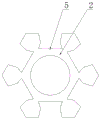
FIG. 1 is a schematic structural diagram of the present invention in accordance with one embodiment;
FIG. 2 is a schematic structural view of a rack unit of the present invention in accordance with one embodiment;
FIG. 3 is a schematic cross-sectional view of the spindle of the present invention according to one embodiment;
FIG. 4 is a schematic view of a main structure of the edge banding formwork of the present invention according to the first embodiment;
FIG. 5 is a schematic structural diagram of a transverse form body according to the present invention in accordance with one embodiment;
FIG. 6 is a schematic view of the main structure of the longitudinal form of the present invention according to one embodiment;
FIG. 7 is a schematic structural diagram of a main body of the forward and oblique form of the present invention according to one embodiment;
FIG. 8 is a schematic structural diagram of a main body of a reverse-inclined form according to the first embodiment of the present invention;
FIG. 9 is a schematic view of the driving mechanism of the present invention according to one embodiment;
fig. 10 is a schematic structural view of the spindle of the present invention in the second embodiment.
In the figure: the device comprises a template support 1, a main shaft 2, a support unit 3, a template main body 4, a sliding chute 5, a sliding block 6, an upper template 7, a lower template 8, a hollowed-out rail 9, a transmission case 10, a worm 11, a worm wheel 12, a transmission shaft 13, a belt pulley 14, a shaft shoulder 21, a shaft sleeve 22, an edge sealing template main body 401, a transverse template main body 402, a longitudinal template main body 403, a forward oblique template main body 404 and a reverse oblique template main body 405.
Detailed Description
The present application will now be described in further detail with reference to the drawings, it should be noted that the following detailed description is given for illustrative purposes only and is not to be construed as limiting the scope of the present application, as those skilled in the art will be able to make numerous insubstantial modifications and adaptations to the present application based on the above disclosure.
Example one
As shown in fig. 1-9, the line conveying template for the side piece surface of the down jacket comprises a template support 1, a driving mechanism and a template main body 4, wherein the template support 1 comprises a main shaft 2 and a plurality of support units 3 arranged on the main shaft 2, one end of the main shaft 2 is connected with the driving mechanism, and the template main body 4 is arranged on the support units 3. The driving mechanism drives the main shaft 2 to rotate, so that the support units 3 are driven to rotate around the main shaft 2, and the support units 3 can be switched to the template main body 4 positioned at the top of the template support 1 through rotation.
The cross section of the support unit 3 is triangular, the inner end of the support unit 3 is detachably connected with the main shaft 2, the main shaft 2 is provided with a plurality of sliding grooves 5, the inner end of the support unit 3 is provided with a sliding block 6 matched with the sliding grooves 5, and the sliding block 6 is embedded into the sliding grooves 5 to connect the support unit 3 with the main shaft 2. The slider 6 of the holder unit 3 is inserted into the main shaft 2 along one end of the slide groove 5 of the main shaft 2, moves along the slide groove 5, moves the holder unit 3 to the mounting position, and is then fixed to the main shaft 2 by a pin to fix the holder unit 3.
The two ends of the sliding block 6 of the support unit 3 extend to the two sides of the support unit 3 to form an extending part of the sliding block 6, the extending part of the sliding block 6 is provided with a pin hole, and the main shaft 2 is provided with a pin hole matched with the extending part of the sliding block 6.
Preferably, a plurality of support units 3 are spliced to form a polygonal prism structure. It is possible to form a fit between the holder units 3 while being connected with the main shaft 2, so that the stability of the entire formwork holder 1 can be improved.
Preferably, the corresponding positions of the two surfaces of the bracket unit 3 are respectively provided with a projection and a recess which are arranged along the axial direction. In the arch can be embedded into sunken when support unit 3 splices, fix a position between support unit 3, avoid the dislocation between support unit 3.
The outside of support unit 3 is equipped with template main part 4, and template main part 4 includes cope match-plate pattern 7 and lower bolster 8, and the one side that is close to support unit 3 is located to lower bolster 8, and the inside of lower bolster 8 is equipped with the recess that holds the lateral plate, is equipped with corresponding fretwork track 9 on cope match-plate pattern 7 and the cope match-plate pattern 7, and fretwork track 9 link up cope match-plate pattern 7 and lower bolster 8. The hollowed-out rail 9 is used as a sewing track of the sewing machine, gives a sewing walking space for the sewing machine, and sews the side piece between the upper template 7 and the lower template 8.
Template main part 4 and the detachable connection of support unit 3, specifically the outside of support unit 3 is equipped with the mounting groove with 4 interference fit of template main part, and in template main part 4 imbed this mounting groove, this kind of mode was convenient for change template main part 4, makes through the expansion of changing template main part 4 in order to carry out unlimited kind of template under the limited condition of support unit 3.
The driving mechanism comprises a transmission case 10, a worm 11, a worm wheel 12, a transmission shaft 13 and belt wheels 14, the transmission shaft 13 is arranged at the center inside the transmission case 10, one end of the transmission shaft 13 is connected with the main shaft 2 through a spline or a connector, the worm wheel 12 is fixedly arranged on the transmission shaft 13, two sides of the worm wheel 12 are respectively meshed with one worm 11, two ends of the worm 11 are connected with the transmission case 10 through bearings, the two worm 11 are respectively and fixedly provided with one belt wheel 14, the two belt wheels 14 are connected through a belt, and one worm 11 extends to the outer side of the transmission case 10 and is connected with a power source. The power source can be a manual power source such as a hand wheel or a mechanical power source such as a motor, the worm 11 can extend to the outer side of the transmission case 10 and be fixedly connected with the hand wheel, or be connected with an output shaft of the motor through a coupling. Preferably, the motor is a servo motor. Angular displacement can be conveniently controlled.
The power source drives the worm 11 to rotate, the worm 11 drives the worm wheel 12 meshed with the worm 11 to rotate, so that the transmission shaft 13 is driven to rotate, the main shaft 2 is driven to rotate through the transmission shaft 13, the mold support on the main shaft 2 is driven to rotate, the mold main body is driven to change positions, and the mold main body located at the top working position is switched;
meanwhile, the worm 11 rotates and simultaneously drives the belt wheels 14 to rotate, the belt between the two belt wheels 14 drives the two worms 11 to synchronously rotate, the other worm 11 is prevented from generating self-locking on the worm wheel 12, when the motor stops rotating, the worm 11 stops rotating and generates self-locking on the worm wheel 12, the rotation of the transmission shaft 13 and the main shaft 2 is limited, and the rotation of the mold support in the sewing process is avoided.
Preferably, both ends of the main shaft 2 are mounted on the frame through bearings. The frame realizes the support for the main shaft 2.
The line conveying template for the side piece surface of the down jacket is arranged below a machine head of the template sewing machine. The template sewing machine is matched with the existing template sewing machine for use.
The working principle of the invention; a plurality of template main bodies 4 are arranged on a support unit 3 of a mold support in advance, and different template main bodies 4 can be rotatably switched to sew different pieces when the pieces or other pieces are sewn, so that the sewing machine is suitable for sewing different batches of pieces or sewing different modes of the pieces.
For example, edge sealing, transverse, longitudinal, forward oblique and backward oblique sewing are required to be sequentially performed on the side panel, the edge sealing template main body 401, the transverse template main body 402, the longitudinal template main body 403, the forward oblique template main body 404 and the backward oblique template main body 405 are respectively configured for the above processes, and the hollowed-out rails 9 corresponding to the sewing tracks of the processes are arranged on each template;
when the edge sealing is sewn, the edge sealing template main body 401 is rotated to the top, then the side piece is placed into the edge sealing template main body 401, and the template sewing machine performs edge sealing sewing on the side piece;
when in transverse sewing, the transverse template main body 402 is rotated to the top, then the side piece is placed into the transverse template main body 402, and the template sewing machine performs transverse sewing on the side piece;
during longitudinal sewing, the longitudinal template main body 403 is rotated to the top, then the side piece is placed into the longitudinal template main body 403, and the template sewing machine performs longitudinal sewing on the side piece to form grid-shaped sewing lines on the side piece;
when in forward and oblique sewing, the forward and oblique template main body 404 is rotated to the top, then the side piece is placed into the forward and oblique template main body 404, and the template sewing machine performs forward and oblique sewing on the side piece;
when the reverse oblique sewing is performed, the reverse oblique template main body 405 is rotated to the top, then the side piece is placed into the reverse oblique template main body 405, the template sewing machine performs the reverse oblique sewing on the side piece, and a diamond-shaped sewing line is formed on the side piece.
Preferably, the forward-oblique template main body 404 is provided with a plurality of inclined hollow tracks 9 which are arranged at a certain angle with the long edges of the template main body 4, and the backward-oblique template main body 405 is provided with hollow tracks 9 which are symmetrical to the hollow tracks 9 on the forward-oblique template main body 404, so as to form crossed rhombic stitches.
Example two
As shown in fig. 10, the line conveying template for the side piece surface of the down jacket comprises a template support 1, a driving mechanism and a template main body 4, wherein the template support 1 comprises a main shaft 2 and a plurality of support units 3 arranged on the main shaft 2, one end of the main shaft 2 is connected with the driving mechanism, and the template main body 4 is arranged on the support units 3. The driving mechanism drives the main shaft 2 to rotate, so that the support units 3 are driven to rotate around the main shaft 2, and the support units 3 can be switched to the template main body 4 positioned at the top of the template support 1 through rotation.
The cross section of the support unit 3 is triangular, the inner end of the support unit 3 is detachably connected with the main shaft 2, the main shaft 2 is provided with a plurality of sliding grooves 5, the inner end of the support unit 3 is provided with a sliding block 6 matched with the sliding grooves 5, and the sliding block 6 is embedded into the sliding grooves 5 to connect the support unit 3 with the main shaft 2. The slider 6 of the holder unit 3 is inserted into the main shaft 2 along one end of the slide groove 5 of the main shaft 2, moves along the slide groove 5, moves the holder unit 3 to the mounting position, and is then fixed to the main shaft 2 by a pin to fix the holder unit 3.
A shaft shoulder 21 is arranged on the main shaft 2 at one side of the support unit 3, the shaft shoulder 21 can block one side of the support unit 3, a shaft sleeve 22 is arranged on the main shaft 2 at the other side of the support unit 3, and the shaft sleeve 22 is sleeved on the main shaft 2 and is connected with the main shaft 2 through a pin. After the support unit 3 is mounted, the shaft sleeve 22 is sleeved, then the shaft sleeve 22 is fixed through a pin, and the support unit 3 is axially limited by the aid of the shaft sleeve 22 matched with the shaft shoulder 21.
The above-mentioned embodiments only express several embodiments of the present invention, and the description thereof is more specific and detailed, but not construed as limiting the scope of the present invention. It should be noted that, for a person skilled in the art, several variations and modifications can be made without departing from the inventive concept, which falls within the scope of the present invention.
Claims (3)
1. The utility model provides a down coat side piece face fortune line template which characterized in that: the template support comprises a main shaft and a plurality of support units arranged on the main shaft, one end of the main shaft is connected with the driving mechanism, and the support units are provided with template main bodies; the driving mechanism drives the main shaft and the bracket unit to rotate;
the cross section of the bracket unit is triangular, and the inner end of the bracket unit is detachably connected with the main shaft;
two ends of a sliding block of the support unit extend to two sides of the support unit to form sliding block extending parts, pin holes are formed in the sliding block extending parts, and pin holes matched with the sliding block extending parts are formed in the main shaft;
a shaft shoulder is arranged on the main shaft at one side of the support unit and can block one side of the support unit, and a shaft sleeve is arranged on the main shaft at the other side of the support unit and sleeved on the main shaft and connected with the main shaft through a pin;
the template main body is arranged outside the support unit and comprises an upper template and a lower template, the lower template is arranged on one surface close to the support unit, a groove for containing a side piece is formed in the lower template, corresponding hollowed-out rails are arranged on the upper template and the lower template, and the hollowed-out rails penetrate through the upper template and the lower template;
the main shaft is provided with a plurality of sliding grooves, the inner end of the support unit is provided with a sliding block matched with the sliding grooves, and the sliding block is embedded into the sliding grooves to connect the support unit with the main shaft;
the template main body is detachably connected with the support unit, specifically, a mounting groove in interference fit with the template main body is arranged outside the support unit, and the template main body is embedded into the mounting groove.
2. The side panel surface line conveying template for the down jacket as claimed in claim 1, wherein: the plurality of support units are spliced to form a polygonal prism structure.
3. The side panel surface line conveying template for the down jacket as claimed in claim 1, wherein: the driving mechanism comprises a transmission case, a worm wheel, a transmission shaft and belt wheels, the transmission shaft is arranged at the center of the interior of the transmission case, one end of the transmission shaft is connected with the main shaft through a connector, the worm wheel is fixedly arranged on the transmission shaft, the two sides of the worm wheel are respectively meshed with the worm, the two ends of the worm are connected with the transmission case through bearings, the two worm are respectively fixedly provided with one belt wheel, the two belt wheels are connected through a belt, and the worm extends to the outer side of the transmission case and is connected with a power source.
Priority Applications (1)
| Application Number | Priority Date | Filing Date | Title |
|---|---|---|---|
| CN201911060201.XA CN110731562B (en) | 2019-11-01 | 2019-11-01 | Down jacket side sheet surface line conveying template |
Applications Claiming Priority (1)
| Application Number | Priority Date | Filing Date | Title |
|---|---|---|---|
| CN201911060201.XA CN110731562B (en) | 2019-11-01 | 2019-11-01 | Down jacket side sheet surface line conveying template |
Publications (2)
| Publication Number | Publication Date |
|---|---|
| CN110731562A CN110731562A (en) | 2020-01-31 |
| CN110731562B true CN110731562B (en) | 2021-11-23 |
Family
ID=69272067
Family Applications (1)
| Application Number | Title | Priority Date | Filing Date |
|---|---|---|---|
| CN201911060201.XA Active CN110731562B (en) | 2019-11-01 | 2019-11-01 | Down jacket side sheet surface line conveying template |
Country Status (1)
| Country | Link |
|---|---|
| CN (1) | CN110731562B (en) |
Citations (5)
| Publication number | Priority date | Publication date | Assignee | Title |
|---|---|---|---|---|
| CN202232061U (en) * | 2011-07-01 | 2012-05-30 | 浙江鸿牛工贸有限公司 | Integrated box transmission device for micro-cultivator |
| CN203435755U (en) * | 2013-07-29 | 2014-02-19 | 波司登羽绒服装有限公司 | Run-stitching template of side part surface of down jacket |
| CN105063908A (en) * | 2015-07-24 | 2015-11-18 | 东莞市名菱工业自动化科技有限公司 | Multi-station automatic rotary feeding mechanism |
| CN205907467U (en) * | 2016-08-08 | 2017-01-25 | 宁波舒普机电股份有限公司 | A swivel feeding platform for sewing machine template |
| CN206467412U (en) * | 2017-01-25 | 2017-09-05 | 江苏宝美户外用品股份有限公司 | A kind of down jackets lateral plate transport line splices and combines template |
-
2019
- 2019-11-01 CN CN201911060201.XA patent/CN110731562B/en active Active
Patent Citations (5)
| Publication number | Priority date | Publication date | Assignee | Title |
|---|---|---|---|---|
| CN202232061U (en) * | 2011-07-01 | 2012-05-30 | 浙江鸿牛工贸有限公司 | Integrated box transmission device for micro-cultivator |
| CN203435755U (en) * | 2013-07-29 | 2014-02-19 | 波司登羽绒服装有限公司 | Run-stitching template of side part surface of down jacket |
| CN105063908A (en) * | 2015-07-24 | 2015-11-18 | 东莞市名菱工业自动化科技有限公司 | Multi-station automatic rotary feeding mechanism |
| CN205907467U (en) * | 2016-08-08 | 2017-01-25 | 宁波舒普机电股份有限公司 | A swivel feeding platform for sewing machine template |
| CN206467412U (en) * | 2017-01-25 | 2017-09-05 | 江苏宝美户外用品股份有限公司 | A kind of down jackets lateral plate transport line splices and combines template |
Also Published As
| Publication number | Publication date |
|---|---|
| CN110731562A (en) | 2020-01-31 |
Similar Documents
| Publication | Publication Date | Title |
|---|---|---|
| CN206768370U (en) | A kind of multilayer cloth merges sewing structure | |
| CN104082910B (en) | Full-automatic non-woven cloth shoe cover cap seaming machine | |
| CN206047855U (en) | One kind carries efficient multistation letter out machine | |
| CN112831957A (en) | Processing and forming method of multilayer garment fabric | |
| CN110731562B (en) | Down jacket side sheet surface line conveying template | |
| CN110820175A (en) | Non-ironing sewing production line integrating bright lines and dark lines of clothes cut pieces | |
| CN107164881A (en) | A kind of Intelligent sewing machine of individual motor feeding | |
| CN107012265A (en) | A kind of leather shoes production leather sanding and polishing device | |
| CN206706409U (en) | Dyeing and finishing sanding processing unit | |
| CN207713919U (en) | A kind of novel lateral quilter | |
| CN104499209B (en) | Automatic garment making equipment | |
| CN110435281A (en) | A kind of Novel cloth compounding machine | |
| CN213538346U (en) | Double faced pile edge sewing device | |
| CN210436788U (en) | Moxa traditional chinese medicine is all spread and is spilt compounding machine | |
| CN204325697U (en) | A kind of seam embroidery machine | |
| US3180292A (en) | Rotatable workholder in combination with a travelling sewing machine | |
| CN202626564U (en) | Forming mould device for special-shaped seam line outline of single needle machine | |
| CN109440306B (en) | Multi-head electronic automatic sewing machine set | |
| CN206843728U (en) | A kind of Intelligent sewing machine of individual motor feeding | |
| CN104404714B (en) | One kind seam embroidery machine | |
| CN207812064U (en) | A kind of bead string embroidery machine | |
| CN108796911A (en) | Color-fixing device is banked up in a kind of cold rolling printing and dyeing | |
| CN106988029A (en) | Full-automatic side seam sewing machine | |
| CN218699874U (en) | Nixing pottery rolling forming machine | |
| CN214547570U (en) | Automatic button sewing machine for tailoring |
Legal Events
| Date | Code | Title | Description |
|---|---|---|---|
| PB01 | Publication | ||
| PB01 | Publication | ||
| SE01 | Entry into force of request for substantive examination | ||
| SE01 | Entry into force of request for substantive examination | ||
| GR01 | Patent grant | ||
| GR01 | Patent grant | ||
| TR01 | Transfer of patent right |
Effective date of registration: 20230612 Address after: 310016 room 206, 2nd floor, building 2, No.1 Jiuhua Road, Jianggan District, Hangzhou City, Zhejiang Province Patentee after: GAOFAN (Zhejiang) Information Technology Co.,Ltd. Address before: 230000 room 330, building F4, phase II, innovation industrial park, high tech Zone, Hefei City, Anhui Province Patentee before: Anhui zhongyilian Supply Chain Management Service Co.,Ltd. |
|
| TR01 | Transfer of patent right |