CN110725552B - Steel stand horizontal alignment device - Google Patents

Steel stand horizontal alignment device Download PDF

Info

Publication number
CN110725552B
CN110725552B CN201910866267.1A CN201910866267A CN110725552B CN 110725552 B CN110725552 B CN 110725552B CN 201910866267 A CN201910866267 A CN 201910866267A CN 110725552 B CN110725552 B CN 110725552B
Authority
CN
China
Prior art keywords
groups
steel column
steel
horizontal straightening
plates
Prior art date
Legal status (The legal status is an assumption and is not a legal conclusion. Google has not performed a legal analysis and makes no representation as to the accuracy of the status listed.)
Active
Application number
CN201910866267.1A
Other languages
Chinese (zh)
Other versions
CN110725552A (en
Inventor
何伟
Current Assignee (The listed assignees may be inaccurate. Google has not performed a legal analysis and makes no representation or warranty as to the accuracy of the list.)
Anhui Zhongyuan Environmental Protection Technology Co ltd
Original Assignee
Anhui Zhongyuan Environmental Protection Technology Co ltd
Priority date (The priority date is an assumption and is not a legal conclusion. Google has not performed a legal analysis and makes no representation as to the accuracy of the date listed.)
Filing date
Publication date
Application filed by Anhui Zhongyuan Environmental Protection Technology Co ltd filed Critical Anhui Zhongyuan Environmental Protection Technology Co ltd
Priority to CN201910866267.1A priority Critical patent/CN110725552B/en
Publication of CN110725552A publication Critical patent/CN110725552A/en
Application granted granted Critical
Publication of CN110725552B publication Critical patent/CN110725552B/en
Active legal-status Critical Current
Anticipated expiration legal-status Critical

Links

Images

Classifications

    • EFIXED CONSTRUCTIONS
    • E04BUILDING
    • E04GSCAFFOLDING; FORMS; SHUTTERING; BUILDING IMPLEMENTS OR AIDS, OR THEIR USE; HANDLING BUILDING MATERIALS ON THE SITE; REPAIRING, BREAKING-UP OR OTHER WORK ON EXISTING BUILDINGS
    • E04G21/00Preparing, conveying, or working-up building materials or building elements in situ; Other devices or measures for constructional work
    • E04G21/14Conveying or assembling building elements
    • E04G21/16Tools or apparatus
    • E04G21/162Handles to carry construction blocks
    • EFIXED CONSTRUCTIONS
    • E04BUILDING
    • E04GSCAFFOLDING; FORMS; SHUTTERING; BUILDING IMPLEMENTS OR AIDS, OR THEIR USE; HANDLING BUILDING MATERIALS ON THE SITE; REPAIRING, BREAKING-UP OR OTHER WORK ON EXISTING BUILDINGS
    • E04G21/00Preparing, conveying, or working-up building materials or building elements in situ; Other devices or measures for constructional work
    • E04G21/14Conveying or assembling building elements
    • E04G21/16Tools or apparatus
    • E04G21/18Adjusting tools; Templates

Landscapes

  • Engineering & Computer Science (AREA)
  • Architecture (AREA)
  • Mechanical Engineering (AREA)
  • Civil Engineering (AREA)
  • Structural Engineering (AREA)
  • Conveying And Assembling Of Building Elements In Situ (AREA)

Abstract

本发明公开了一种钢立柱水平调直装置,包括用于承托钢立柱的水平调直架,所述水平调直架由两组面板和两组底板构成,两组所述面板之间具有间隙,间隙中滑动设置有两组钢柱夹持机构,所述撑板表面固定安装有螺纹轴套,撑板通过螺纹轴套配合连接有螺杆,所述钢柱夹持机构相对于螺杆位置的一侧表面固定安装有限位机构,所述螺杆一端与对应位置的限位机构连接。本发明结构简单,将水平调直架固定安装在钢立柱安装位置,在钢立柱起吊时,将钢立柱插设在水平调直架上,通过钢柱夹持机构将钢立柱稳定夹持,然后进行吊装另一组钢立柱,通过转动螺杆,能够很方便的调整两个钢立柱之间的水平距离,从而提高了钢立柱安装的效率,提高了钢立柱安装的精度。

Figure 201910866267

The invention discloses a horizontal straightening device for a steel column, comprising a horizontal straightening frame for supporting the steel vertical column, the horizontal straightening frame is composed of two sets of panels and two sets of bottom plates, and a Gap, two sets of steel column clamping mechanisms are slidably arranged in the gap, a threaded bushing is fixedly installed on the surface of the support plate, and the support plate is connected with a screw rod through the threaded bushing, and the steel column clamping mechanism is relative to the position of the screw rod. A limiting mechanism is fixedly installed on the surface of one side, and one end of the screw rod is connected with the limiting mechanism at the corresponding position. The invention has a simple structure. The horizontal straightening frame is fixedly installed at the installation position of the steel column. When the steel column is lifted, the steel column is inserted into the horizontal straightening frame. To hoist another group of steel columns, by rotating the screw, the horizontal distance between the two steel columns can be easily adjusted, thereby improving the installation efficiency of the steel columns and the installation accuracy of the steel columns.

Figure 201910866267

Description

Steel stand horizontal alignment device
Technical Field
The invention relates to the technical field of steel upright posts, in particular to a horizontal straightening device for a steel upright post.
Background
In the building, water and electricity engineering work progress, often can adopt the steel stand of major diameter steel pipe preparation as bearing structure, the steel stand is generally highly 3m to 12m, and the method that construction unit hoist and mount steel stand adopted usually is: after the steel upright post is unloaded, the steel upright post is flatly placed at the installation position, the upper half part of the steel upright post is bound by a steel wire rope winding, an upper layer of steel wire rope is used for pressing a lower layer of steel wire rope, the lower layer of steel wire rope is locked by a U-shaped snap ring, and then the steel upright post is turned over and vertically hoisted. After hoisting, the steel upright post needs to be stabilized to keep the steel upright post in a vertical state, and then the lower end of the steel upright post is fixed.
At present in a plurality of steel stand installation, the distance between them is not good to be adjusted, and the deviation of position probably takes place for the steel stand in the installation, leads to after the installation, still need dismantle the steel stand again, has increased labour cost, and the process is wasted time and energy.
Disclosure of Invention
The invention aims to provide a horizontal straightening device for a steel upright post.
In order to achieve the purpose, the technical scheme adopted by the invention is as follows: the utility model provides a steel stand horizontal alignment device, is including the horizontal alignment frame that is used for bearing the steel stand, the horizontal alignment frame comprises two sets of panels and two sets of bottom plates, and is two sets of clearance has between the panel, and it is provided with two sets of steel column fixture to slide in the clearance, and is two sets of the panel is located two sets of respectively the bottom plate top, and is two sets of the panel is with two sets of the bottom plate both ends all are provided with the fagging, and are two sets of the panel both ends are all through fagging and two sets of bottom plate fixed connection, form between panel and the bottom plate and press from both sides the notch, fagging fixed surface installs the screw thread axle sleeve, and the fagging is connected with the screw rod through the cooperation of screw thread axle sleeve, steel column fixture installs stop gear for one side fixed surface of screw rod position, screw rod one end is connected with the stop gear who corresponds the position.
Preferably, the steel column clamping mechanism comprises two half collar plates, protruding plates are fixedly arranged on the surfaces of one sides of the two half collar plates corresponding to the clamping groove openings, the two protruding plates are fixedly connected through bolts, and the protruding plates are movably inserted into the clamping groove openings.
Preferably, the limiting mechanism is a limiting disc, the limiting disc is fixedly welded on the outer side surface of the half-clamping ring plate, an annular limiting groove is formed in the limiting disc, one end of the screw is movably inserted into the limiting disc, one end of the screw is fixedly sleeved with a lantern ring in the limiting disc, and the lantern ring is movably clamped with the annular limiting groove.
Preferably, the bottom plate upper surface has seted up the holding tank along the board length direction, and even movable mounting has the multiunit roller bearing in the holding tank, and the roller bearing upper surface is higher than the bottom plate upper surface.
Preferably, the longitudinal length of the protruding plate corresponds to the distance between the upper surface of the roller and the lower surface of the panel.
Preferably, a curved handle is fixedly welded at the other end of the screw rod.
Compared with the prior art, the invention has the advantages that:
the steel column lifting device is simple in structure, the horizontal straightening frame is fixedly arranged at the installation position of the steel column, the steel column is inserted on the horizontal straightening frame when the steel column is lifted, the steel column is stably clamped through the steel column clamping mechanism, then another group of steel columns is lifted, and the horizontal distance between the two steel columns can be conveniently adjusted by rotating the screw rod, so that the installation efficiency of the steel column is improved, and the installation accuracy of the steel column is improved.
Drawings
In order to more clearly illustrate the embodiments of the present invention or the technical solutions in the prior art, the drawings used in the description of the embodiments or the prior art will be briefly described below, it is obvious that the drawings in the following description are only some embodiments of the present invention, and for those skilled in the art, other drawings can be obtained according to the drawings without creative efforts.
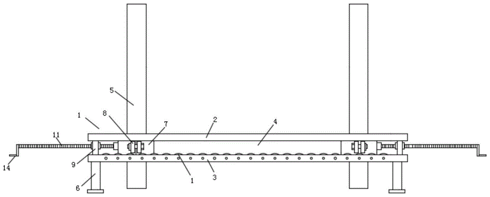
FIG. 1 is a structural view of a horizontal straightening device for a steel column according to the present invention;
FIG. 2 is a cross-sectional view of a steel stud horizontal straightening device of the present invention;
FIG. 3 is a side view of a steel column horizontal straightening device of the present invention;
FIG. 4 is an enlarged view of the structure at A in FIG. 2;
fig. 5 is a structural view of a half-collar plate of the present invention.
In the figure: the vertical type steel plate support comprises a horizontal straightening frame 1, a panel 2, a bottom plate 3, a clamping groove opening 4, a steel upright post 5, supporting legs 6, a half clamping ring plate 7, a protruding plate 8, a supporting plate 9, a threaded shaft sleeve 10, a screw rod 11, an accommodating groove 12, a rolling shaft 13, a curved handle 14, a limiting disc 15, a ring-shaped limiting groove 16 and a lantern ring 17.
Detailed Description
The preferred embodiments of the present invention will be described in detail below with reference to the accompanying drawings so that the advantages and features of the present invention can be more easily understood by those skilled in the art, and the scope of the present invention will be more clearly and clearly defined.
Referring to fig. 1-5, the invention provides a steel column horizontal straightening device, which comprises a horizontal straightening frame 1 for supporting a steel column 5, wherein the horizontal straightening frame 1 is installed at a position where the steel column needs to be installed, the horizontal straightening frame 1 is composed of two groups of panels 2 and two groups of bottom plates 3, a gap is formed between the two groups of panels 2, two groups of steel column clamping mechanisms are slidably arranged in the gap, the two groups of panels 2 are respectively positioned above the two groups of bottom plates 3, supporting plates 9 are respectively arranged at two ends of the two groups of panels 2 and the two groups of bottom plates 3, two ends of the two groups of panels 2 are fixedly connected with the two groups of bottom plates 3 through the supporting plates 9, a clamping groove opening 4 is formed between the panels 2 and the bottom plates 3, a threaded shaft sleeve 10 is fixedly arranged on the surface of each supporting plate 9, a screw rod 11 is connected with the corresponding to the matching of the threaded shaft sleeve 10, and a limiting mechanism is fixedly arranged on one side surface of the steel column clamping mechanism corresponding to the screw rod 11, one end of the screw rod 11 is connected with a limiting mechanism at a corresponding position.
In this embodiment, steel column fixture includes two half rand boards 7, and two half rand boards 7 are all fixed for a side surface that presss from both sides notch 4 position and are provided with protrusion board 8, and two protrusion boards 8 pass through bolt fixed connection, and protrusion board 8 is all movable insert to be located in pressing from both sides notch 4.
In this embodiment, stop gear is spacing dish 15, and spacing dish 15 fixed welding is on half rand board 7 outside surface, and spacing dish 15 is inside to have seted up ring type spacing groove 16, and screw rod 11 one end activity is inserted and is located spacing dish 15, and screw rod 11 one end is located the fixed cover of spacing dish 15 and is equipped with lantern ring 17, lantern ring 17 and the 16 activity blocks of ring type spacing groove, and through rotating screw rod 11, screw rod 11 can promote and stimulate half rand board 7 and remove to the horizontal position of adjustment steel stand 5.
In this embodiment, holding tank 12 has been seted up along board length direction 3 to 3 upper surfaces of bottom plate, and even movable mounting has multiunit roller bearing 13 in the holding tank 12, and roller bearing 13 upper surface is higher than 3 upper surfaces of bottom plate, through the rotation of roller bearing 13, has guaranteed that protrusion board 8 can be in pressing from both sides more convenient removal in notch 4.
In this embodiment, the longitudinal length of the protruding plate 8 corresponds to the distance between the upper surface of the roller 13 and the lower surface of the panel 2, so that the protruding plate 8 can be clamped between the clamping notches 4, the protruding plate 8 is prevented from deflecting, the stability of the steel column 5 is ensured, and the steel column 5 can be kept in a vertical state.
In this embodiment, the other end of the screw rod 11 is fixedly welded with a curved handle 14, and the screw rod 11 can be conveniently rotated by a worker through the curved handle 14.
Although the embodiments of the present invention have been described with reference to the accompanying drawings, various changes or modifications may be made by the patentees within the scope of the appended claims, and within the scope of the invention, as long as they do not exceed the scope of the invention described in the claims.

Claims (5)

1. The utility model provides a steel stand horizontal straightening device, is including the horizontal straightening frame that is used for bearing steel stand, its characterized in that: the horizontal straightening frame is composed of two groups of panels and two groups of bottom plates, a gap is formed between the two groups of panels, two groups of steel column clamping mechanisms are arranged in the gap in a sliding mode, the two groups of panels are respectively positioned above the two groups of bottom plates, supporting plates are arranged at two ends of the two groups of panels and two ends of the two groups of bottom plates, two ends of the two groups of panels are fixedly connected with the two groups of bottom plates through the supporting plates, a clamping groove opening is formed between the panels and the bottom plates, threaded shaft sleeves are fixedly arranged on the surfaces of the supporting plates, the supporting plates are connected with screw rods through the threaded shaft sleeves in a matched mode, a limiting mechanism is fixedly arranged on one side surface of each steel column clamping mechanism relative to the positions of the screw rods, and one end of each screw rod is connected with the limiting mechanism at the corresponding position; the steel column clamping mechanism comprises two half clamping ring plates, wherein a protruding plate is fixedly arranged on one side surface of each half clamping ring plate corresponding to the position of the clamping groove opening, the two protruding plates are fixedly connected through bolts, and the protruding plates are movably inserted into the clamping groove openings.
2. The steel column horizontal straightening device according to claim 1, characterized in that: the limiting mechanism is a limiting disc, the limiting disc is fixedly welded on the outer side surface of the half-clamping ring plate, an annular limiting groove is formed in the limiting disc, one end of the screw is movably inserted into the limiting disc, a sleeve ring is fixedly sleeved in the limiting disc at one end of the screw, and the sleeve ring is movably clamped with the annular limiting groove.
3. The steel column horizontal straightening device according to claim 1, characterized in that: the bottom plate upper surface has seted up the holding tank along the board length direction, and even movable mounting has the multiunit roller bearing in the holding tank, and the roller bearing upper surface is higher than the bottom plate upper surface.
4. A steel column horizontal straightening device according to any one of claims 1 to 3, characterized in that: the longitudinal length of the protruding plate corresponds to the distance between the upper surface of the rolling shaft and the lower surface of the panel.
5. The steel column horizontal straightening device according to claim 1, characterized in that: and a curved handle is fixedly welded at the other end of the screw rod.
CN201910866267.1A 2019-09-12 2019-09-12 Steel stand horizontal alignment device Active CN110725552B (en)

Priority Applications (1)

Application Number Priority Date Filing Date Title
CN201910866267.1A CN110725552B (en) 2019-09-12 2019-09-12 Steel stand horizontal alignment device

Applications Claiming Priority (1)

Application Number Priority Date Filing Date Title
CN201910866267.1A CN110725552B (en) 2019-09-12 2019-09-12 Steel stand horizontal alignment device

Publications (2)

Publication Number Publication Date
CN110725552A CN110725552A (en) 2020-01-24
CN110725552B true CN110725552B (en) 2021-11-23

Family

ID=69218144

Family Applications (1)

Application Number Title Priority Date Filing Date
CN201910866267.1A Active CN110725552B (en) 2019-09-12 2019-09-12 Steel stand horizontal alignment device

Country Status (1)

Country Link
CN (1) CN110725552B (en)

Citations (5)

* Cited by examiner, † Cited by third party
Publication number Priority date Publication date Assignee Title
DE19649299A1 (en) * 1996-11-28 1998-06-04 Bessey & Sohn Window fitting jig
DE29809328U1 (en) * 1998-05-23 1998-09-03 Kütemann, Gerd, 29683 Fallingbostel Element anchor
CN202555656U (en) * 2012-05-14 2012-11-28 厦门市逸超实业有限公司 Width adjusting device of roller forming machine
CN106862309A (en) * 2017-04-19 2017-06-20 四川省隆昌诚信印务有限公司 A kind of efficient correction smoothing component for being applied to silicon steel post
CN106862310A (en) * 2017-04-19 2017-06-20 四川科星药业有限公司 Silicon steel pillar height effect correction levelling machine

Patent Citations (5)

* Cited by examiner, † Cited by third party
Publication number Priority date Publication date Assignee Title
DE19649299A1 (en) * 1996-11-28 1998-06-04 Bessey & Sohn Window fitting jig
DE29809328U1 (en) * 1998-05-23 1998-09-03 Kütemann, Gerd, 29683 Fallingbostel Element anchor
CN202555656U (en) * 2012-05-14 2012-11-28 厦门市逸超实业有限公司 Width adjusting device of roller forming machine
CN106862309A (en) * 2017-04-19 2017-06-20 四川省隆昌诚信印务有限公司 A kind of efficient correction smoothing component for being applied to silicon steel post
CN106862310A (en) * 2017-04-19 2017-06-20 四川科星药业有限公司 Silicon steel pillar height effect correction levelling machine

Also Published As

Publication number Publication date
CN110725552A (en) 2020-01-24

Similar Documents

Publication Publication Date Title
CN210849022U (en) An I-beam turning device
CN110466980B (en) Frame turnover device of wind generating set
CN110725552B (en) Steel stand horizontal alignment device
CN215393524U (en) A turnover device for steel member
CN221183459U (en) Anti-corrosion device for dip-coating of concrete steel cage
CN211078298U (en) Hoisting accessory is used in thermal power plant's maintenance
CN113622412A (en) Pile foundation reinforcement cage position control device and installation method
CN205077842U (en) Multi -use architecture support
CN210316214U (en) Assembled steel construction building dysmorphism post
CN107829061B (en) Full-automatic small part hot dip galvanizing production line is with upset manipulator
CN204983435U (en) A lift strutting arrangement for various coil of strip die mould
CN114229740B (en) Lifting machine for mounting indoor decoration ceiling plate of building
CN201485204U (en) Gas tank hanging device
CN210505313U (en) Roller hoisting and grabbing equipment
CN211283450U (en) Auxiliary system for rolling large-scale round tiles of thin-wall steel pipes
CN204487512U (en) Busbar makes supporting tool
CN203428849U (en) Detachable hoisting support
CN217581324U (en) Steel stand horizontal straightening device capable of improving mounting efficiency of steel stand
CN220574935U (en) Metal pipeline processing mantle fiber auxiliary device
CN220376091U (en) Steel hoisting mechanism
CN216353673U (en) High structural strength transformer rack
CN120774321B (en) Bent cap steel reinforcement skeleton installation hoist device
CN218375533U (en) Prefabricated floor bearing structure
CN219599423U (en) A clamping device for steel structure processing
CN222971388U (en) A processing device for steel structure bridge

Legal Events

Date Code Title Description
PB01 Publication
PB01 Publication
SE01 Entry into force of request for substantive examination
GR01 Patent grant
GR01 Patent grant
PE01 Entry into force of the registration of the contract for pledge of patent right

Denomination of invention: A horizontal straightening device for steel columns

Granted publication date: 20211123

Pledgee: Anhui Guo Yuan Trust Co.,Ltd.

Pledgor: ANHUI ZHONGYUAN ENVIRONMENTAL PROTECTION TECHNOLOGY Co.,Ltd.

Registration number: Y2025980062183