CN1107194C - Hanging-type lighting installation - Google Patents
Hanging-type lighting installation Download PDFInfo
- Publication number
- CN1107194C CN1107194C CN99110676A CN99110676A CN1107194C CN 1107194 C CN1107194 C CN 1107194C CN 99110676 A CN99110676 A CN 99110676A CN 99110676 A CN99110676 A CN 99110676A CN 1107194 C CN1107194 C CN 1107194C
- Authority
- CN
- China
- Prior art keywords
- housing
- lighting device
- upper opening
- lower edge
- optics
- Prior art date
- Legal status (The legal status is an assumption and is not a legal conclusion. Google has not performed a legal analysis and makes no representation as to the accuracy of the status listed.)
- Expired - Fee Related
Links
Images


Classifications
-
- F—MECHANICAL ENGINEERING; LIGHTING; HEATING; WEAPONS; BLASTING
- F21—LIGHTING
- F21V—FUNCTIONAL FEATURES OR DETAILS OF LIGHTING DEVICES OR SYSTEMS THEREOF; STRUCTURAL COMBINATIONS OF LIGHTING DEVICES WITH OTHER ARTICLES, NOT OTHERWISE PROVIDED FOR
- F21V29/00—Protecting lighting devices from thermal damage; Cooling or heating arrangements specially adapted for lighting devices or systems
- F21V29/50—Cooling arrangements
- F21V29/70—Cooling arrangements characterised by passive heat-dissipating elements, e.g. heat-sinks
- F21V29/83—Cooling arrangements characterised by passive heat-dissipating elements, e.g. heat-sinks the elements having apertures, ducts or channels, e.g. heat radiation holes
-
- F—MECHANICAL ENGINEERING; LIGHTING; HEATING; WEAPONS; BLASTING
- F21—LIGHTING
- F21S—NON-PORTABLE LIGHTING DEVICES; SYSTEMS THEREOF; VEHICLE LIGHTING DEVICES SPECIALLY ADAPTED FOR VEHICLE EXTERIORS
- F21S8/00—Lighting devices intended for fixed installation
- F21S8/04—Lighting devices intended for fixed installation intended only for mounting on a ceiling or the like overhead structures
- F21S8/06—Lighting devices intended for fixed installation intended only for mounting on a ceiling or the like overhead structures by suspension
-
- F—MECHANICAL ENGINEERING; LIGHTING; HEATING; WEAPONS; BLASTING
- F21—LIGHTING
- F21V—FUNCTIONAL FEATURES OR DETAILS OF LIGHTING DEVICES OR SYSTEMS THEREOF; STRUCTURAL COMBINATIONS OF LIGHTING DEVICES WITH OTHER ARTICLES, NOT OTHERWISE PROVIDED FOR
- F21V17/00—Fastening of component parts of lighting devices, e.g. shades, globes, refractors, reflectors, filters, screens, grids or protective cages
- F21V17/007—Fastening of component parts of lighting devices, e.g. shades, globes, refractors, reflectors, filters, screens, grids or protective cages with provision for shipment or storage
-
- F—MECHANICAL ENGINEERING; LIGHTING; HEATING; WEAPONS; BLASTING
- F21—LIGHTING
- F21V—FUNCTIONAL FEATURES OR DETAILS OF LIGHTING DEVICES OR SYSTEMS THEREOF; STRUCTURAL COMBINATIONS OF LIGHTING DEVICES WITH OTHER ARTICLES, NOT OTHERWISE PROVIDED FOR
- F21V23/00—Arrangement of electric circuit elements in or on lighting devices
- F21V23/02—Arrangement of electric circuit elements in or on lighting devices the elements being transformers, impedances or power supply units, e.g. a transformer with a rectifier
-
- F—MECHANICAL ENGINEERING; LIGHTING; HEATING; WEAPONS; BLASTING
- F21—LIGHTING
- F21V—FUNCTIONAL FEATURES OR DETAILS OF LIGHTING DEVICES OR SYSTEMS THEREOF; STRUCTURAL COMBINATIONS OF LIGHTING DEVICES WITH OTHER ARTICLES, NOT OTHERWISE PROVIDED FOR
- F21V29/00—Protecting lighting devices from thermal damage; Cooling or heating arrangements specially adapted for lighting devices or systems
- F21V29/15—Thermal insulation
-
- G—PHYSICS
- G09—EDUCATION; CRYPTOGRAPHY; DISPLAY; ADVERTISING; SEALS
- G09F—DISPLAYING; ADVERTISING; SIGNS; LABELS OR NAME-PLATES; SEALS
- G09F13/00—Illuminated signs; Luminous advertising
- G09F13/04—Signs, boards or panels, illuminated from behind the insignia
- G09F13/06—Signs, boards or panels, illuminated from behind the insignia using individual cut-out symbols or cut-out silhouettes, e.g. perforated signs
Landscapes
- Engineering & Computer Science (AREA)
- General Engineering & Computer Science (AREA)
- Physics & Mathematics (AREA)
- General Physics & Mathematics (AREA)
- Theoretical Computer Science (AREA)
- Power Engineering (AREA)
- Arrangement Of Elements, Cooling, Sealing, Or The Like Of Lighting Devices (AREA)
- Non-Portable Lighting Devices Or Systems Thereof (AREA)
- Securing Globes, Refractors, Reflectors Or The Like (AREA)
Abstract
A luminaire assembly includes an electrical assembly having a housing with a longitudinal axis, a main housing portion, and an outwardly extending lower edge portion. It also includes an optical member having an interior surface and an upper opening. The interior surface includes an end wall disposed about the upper opening. The upper opening receives the elongated housing therethrough and is coaxial therewith, and also has a shape which corresponds to the elongated housing. In a suspended orientation for the luminaire assembly, the housing projects from the upper opening of the optical member so that the lower edge portion is adjacent to the end wall and extends around the upper opening for retaining and suspending the optical member. In a nested orientation the main housing portion of the elongated housing is disposed within the optical member so that the lower edge portion is distal the upper opening.
Description
Technical field
The present invention relates to a kind of lighting device, particularly a kind of suitable indoor lighting device.
Background technology
Except other parts, hanging-type lighting installation generally includes: normally a glass or plastic Optical devices; An electronic installation, it has a normally metal housing that is used for placing therein electronic unit; And one be used for lighting device from the suspended hanging element in suitable position, the crown.In order to protect these single lighting device parts, usually respectively independently with their assemblings, packing and be transported to the user from manufacturing place.The lock out operation of this parts has reduced the risk of traffic-induced damage, and described risk is owing to electronic unit and photophore or more frangible optics be packaged in the same container bring.But, this not only makes manufacturer in transportation with packaging process cost is bigger and increase labour intensity, also make the user of mounting points also increase cost, because the user must identify each different packing to find supporting parts, suitably assemble and install these parts then, to form needed luminaire.In order to finish these tasks, setter is wanted the guidance on the reference manual usually.In addition, before the user must be installed together Optical devices and remaining lighting device through being everlasting, hanging element and electronic unit coupled together and make it be suspended on the roof.
Further, the majority of illumination device assembles up according to user's manual, makes it to form required luminaire.The direction of electronic installation with respect to Optical devices will be coordinated and control to this user's manual usually, and these two kinds of devices are installed together by adjustable support.Particularly, lamp socket has specific direction that the adjustment of this direction is generally included dismounting with respect to Optical devices usually and ressembles a plurality of clampers, reorientates and aligned kickstand and the relative position of adjusting electronic installation, socket and Optical devices, up to forming needed luminaire.In order to finish these operations, all these tasks all will expend a large amount of time and manpower.In addition, if these tasks can not correctly be implemented, will can not form needed luminaire so.
In addition, because many indoor lighting devices comprise a bulb that sends high strength (HID) light, it can produce a large amount of relatively heat, like this electronic installation is had harmful effect, because comprise thermo-responsive electronic component, for example electric capacity in the electronic installation.The temperature of some part of bulb may reach 1100 ℃.On the other hand, compare with bulb, the ballast in the lighting device, electric capacity, relay, starter and other electron component produce less heat usually.For example, the maximum operating temperature of typical capacitance is 90 ℃.Because bulb is arranged in the socket usually, and socket is below case of electronic device and near housing, so heat can pass to thermo-responsive electronic component in the housing from bulb.
In addition, although many lighting devices have open Optical devices (promptly not establishing dividing plate in its bottom), other lighting device also has case type and has bottom closure, this closure member comprises that one is installed to glass or plastic septum (disk) on the Optical devices by a swash plate or hinge, and have a hinge or latch usually, make very convenient near bulb.As having other element, the lighting device of many sealings offers the user with bottom closure, and described bottom closure must be installed on the optical element in the job site.For the user, this just needs more assembly fee to use and the time, and disk can disturb or stop light and reduce luminous efficiency.Typical bottom closure also can make the replacing of bulb difficult more.
At last, the above-mentioned metal shell of lighting device is under-utilized sometimes, because they only are used to hold electronic component and form assembling surface.
Summary of the invention
Therefore, need provide a kind of improved lighting device, for manufacturer, it can reduce manufacturing, packing and freight and time, and same, for the user, it can reduce assembling, installation and labour's expense and time.In addition, improved lighting device should have electronic installation and Optical devices, assembles, installs and form required luminaire under the minimum or effortless situation of effort.This improved home lighting device can also improve hot isolation effect, and bulb is produced and the heat that passes to electronic component reduces or reaches minimum.Improved lighting device also has the manufacturer and the Optical devices that will carry out sealing more cheap the user of fitting operation.In addition, improved lighting device should comprise a case of electronic device that can have other required function.
Main purpose of the present invention provides a kind of lighting device, and for manufacturer, it can reduce assembling, packing and freight and time, and for the user, it also can reduce expense and time aspect installation, labour and time.
Another object of the present invention provides a kind of lighting device, and it can improve the hot isolation effect from the heating bulb to the electronic installation element.
Another object of the present invention provides a kind of lighting device, and it has a bottom closure, and from mounting cost and labour aspect, this closure member can reduce expense.
Also purpose of the present invention provides a kind of lighting device housing, and this housing has additional function and is imbued with aesthetic feeling.
In order to realize above-mentioned purpose of the present invention, feature and advantage, provide a kind of lighting device that is suitable for indoor suspension.This lighting device comprises an electronic installation and Optical devices.Electronic installation comprises that one has the housing of longitudinal axis, a main housing portion and an outward extending lower edge part.This lighting device also comprises an optical element with inner surface and a upper opening.Described inner surface comprises an end wall that is provided with around upper opening.Upper opening holds described housing and coaxial with it, also has the shape corresponding to housing.On the suspension direction of lighting device, the housing of lengthwise stretches out from the upper opening of optical element, makes lower edge part adjacent end wall also around upper opening, to keep and the suspension optical element.On withdrawal or playback direction, the main housing portion of housing is positioned at optical element, and the end of lower edge part is alignd with upper opening.In a preferred embodiment, housing is the toroidal that lengthwise is columniform and upper opening has correspondence.
In another embodiment, lighting device comprises a bottom lock element, be used to seal the annular lower portion opening of optical element, the bottom lock element is installed on the lengthwise housing by the hanging element that extends between housing and closure elements and be arranged in the optical element.In another embodiment of the present invention, lighting device comprises one first and second housing parts, and they separate at the Connection Element and the housing that extend between itself and housing by one.In a preferred embodiment, housing comprises the through hole of a plurality of contiguous ballasts, is used to disperse the heat that ballast produces.
In another embodiment, housing comprises the illumination holes of a plurality of adjacent bottom marginal portion, is used to constitute from bulb pass housing and form the illumination outlet of pattern.In one embodiment, each in a plurality of illumination holes all has the shape of selecting from one group of shape such as rectangle, square, circle, triangle, star and cross.In another embodiment, a plurality of illumination holes have formed predetermined shape, are used to send the light of given shape.
In another embodiment of the present invention, on regaining or playbacking direction, the lower edge part is a coplane with the lower openings of optical element.In another embodiment, be installed on the housing and be used for from the beginning top-hung and hang the hanging element of lighting device and be supported on described suspension direction.
Description of drawings
Below in conjunction with accompanying drawing, be described in detail implementing the preferred embodiments of the present invention, above and other objects of the present invention, feature and advantage will become clearer.
Fig. 1 is the stereogram of first embodiment of lighting device of the present invention;
Fig. 2 a is the three-dimensional installation diagram of first embodiment of lighting device of the present invention;
Fig. 2 b has represented another embodiment of case of electronic device of the present invention, and this housing has and is different from the flange shown in Fig. 2 a;
Fig. 3 a is the schematic diagram of lighting device of the present invention, has represented to be positioned at the lighting device on the playback direction of container, and has an expression playback or regain the section part of direction;
Fig. 3 b is the schematic diagram of lighting device of the present invention, has represented to be positioned at fully the lighting device that shrinks or hang on the direction and mention from container;
Fig. 4 a is the stereogram of second embodiment of lighting device of the present invention, and this device has a upper casing part and a lower case part;
Fig. 4 b is the front view of second embodiment of lighting device of the present invention;
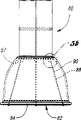
Fig. 5 a is the front view of the 3rd embodiment of lighting device of the present invention;
Fig. 5 b is the enlarged drawing of details shown in Fig. 5 a, and the installation elements of having represented the 3rd embodiment of lighting device of the present invention is installed to the mode on the housing;
Fig. 5 c is the bottom plan view of the 3rd embodiment of lighting device of the present invention;
Fig. 5 d is the enlarged drawing of details shown in Fig. 5 c of lighting device of the present invention, has represented the installation elements that extends between housing and disk; With
Fig. 6 a, 6b, 6c, 6d, 6e, 6f, 6g and 6h have represented the different designs example of illumination holes pattern of the present invention.
The specific embodiment
Referring to Fig. 1, it has represented lighting device 10 of the present invention.Lighting device 10 is specially adapted to the indoor scenarios and the industrial occasions of retail, for example family and open assembly area.Lighting device 10 comprises an electronic installation 12 (Fig. 2 represents in detail) and Optical devices 14.Electronic installation 12 has a housing 16 of preferably being made by metal sheet (other the suitable material with sufficient intensity and heat endurance that perhaps is used for light source), this metal sheet is more cheap than the aluminum hull of the common employing of those housings, and be enough to the direct applied indoor scenarios of preferred embodiment of adaptating lighting device 10, not need to satisfy the sort of in the outdoor environment often be harsh requirement because install 10.As Fig. 1-3 further showed, the housing 16 of electronic installation 12 is (but not necessarily) of lengthwise preferably, and preferably have and be roughly columniform shape or cross section.As shown in Figure 2, housing 16 has formed at least one chamber or cavity 18 therein.Electronic installation 12 also comprises an electric capacity 20, a ballast 22, can also comprise other electron component in other embodiments, for example a starter 24 and/or a relay 26.Electric capacity 20 comprises a heat refraction cover 21.Usually, ballast 22 is to be used to form to start and operated discharge bulb, for example the necessary circuitry condition of high strength luminous (HID) bulb.The housing 16 of electronic installation 10 is relatively large sometimes, because it needs relatively large surface area to disperse the heat that ballast is produced.
Further as illustrated in fig. 1 and 2, lighting device 10 also comprises Optical devices 14, is expressed as an optical element or parts 32 among the figure, and it is luminous to be used for being equipped with different angles according to required light branch.Should be understood that optical element 32 can be to be used for luminous glass any commonly used, plastics or hardware in the prior art, include but not limited to glass or plastic reflective device, refractor, refractor/reflector group component or solid metal reflector.Optical element 32 can have groove and/or the prism that is used to form this light.Optical element 32 has a upper opening 34 on the top that the top circumference is determined and is used to receive bulb 30.Optical element also has an inner surface 33 and an outer surface 35.Inner surface 33 comprises an end wall 57 (shown in Fig. 5 a), and this wall is arranged on around around the upper opening 34.Optical element 32 also has the lower openings 38 that is made of bottom circumference 40, and when lighting device 10 operations, downward light sends to surrounding environment.
As shown in Figure 1 and further referring to Fig. 3 a-3c, upper opening 34 is made the size that can hold cylindrical housings 16.In the process of manufacturer's assembling, packing and transportation light device 10, this point advantageous particularly.Shown in Fig. 3 a-3c, during fabrication, lighting device 10 is assembled, in order to using when mounted.In light of this situation, between erecting stage, the top 17 of cylindrical housings 16 is passed the lower openings 38 of optical element 32 and is inserted upper opening 34.Therefore, Fig. 3 a has shown the lighting device 10 that is positioned at container 25, the direction when it is in transportation (playback or the direction of regaining).Like this, shown in the section among Fig. 3 a part, lighting device 10 is positioned at container 25, the lower edge part 42 of housing 16 and bottom circumference 40 coplanes of optical element 32, and preferably have one from the edge 42 outwardly directed flange portions 43.Then, hanging element 44 can be installed to the top 17 of housing 16.In addition, on the playback direction shown in Fig. 3 a, the main housing of lengthwise housing 16 part (roughly between lower case part 19 and upper casing part 17) is arranged in the optical element 32, makes lower edge part 42 become the end of upper opening 34.That is to say, housing 16 can be arranged in the container 25, at first be lower edge 42, be that optical element 32 inserts its tops then that bottom opening 38 inserts earlier, makes housing 16 pass bottom opening 38 and upper opening 34.And then once hanging element 44 is installed to the top of housing 16, to allow the user device is risen to the suspension shown in Fig. 3 b-3c (or contraction) direction.
As mentioned above, on the playback direction shown in Fig. 3 a, the part of housing 16 is covered and surrounds by optical element 32, like this, for example, in a box or container 25 or when transportation, the flange 42 of housing 16 and bottom periphery 40 coplanes.Therefore, shown in Fig. 3 a, lighting device 10 can be packaged in the independent carton 25 and betransported.Hanging element 44 is usually in manufacturing location is installed in electronic installation 12.Optical devices 14 comprise a upper opening, and the size of this opening is enough to hold therein electronic installation 12.Housing 16 have one from edge, its underpart outward extending lower flange part 42.According to the manufacturing process of lower flange 42, can comprise the continuous flange portion 43 shown in Fig. 2 b ' or Fig. 2 a and 3a-3b shown in separate convex 43.Certainly, should understand fully that such as disclosed in the present invention, this flange portion can comprise can make optical element 32 suspended any projection from the electronic installation 12.
Referring to Fig. 3 b and 3c, wherein shown the contraction of lighting device 10 or hung direction.Especially shown in Fig. 3 b, when the operator lifts lighting device 10 and when will be from position, the crown suspended, lighting device 10 be orientated like this at handle 44 places, promptly it is positioned at outside the container 25.Therefore, lengthwise housing 16 stretches out from the upper opening 34 of optical element 32, makes the lower edge part 42 adjacent upper portions openings 34 of housing 16.In addition, by flange portion 43, the diameter of lower flange 42 is greater than the diameter of upper opening 34, make optical element 32 support and be suspended on lower flange part 43,43 ' on.As shown in figs. 1 and 3, although lighting device 10 can be positioned at indoor multiple direction and position, it is preferably suspended from ceiling or other position, crown, and is supported by the hanging element on the top 17 that is installed in housing 16 44.Fig. 3 c has represented to be arranged on the lighting device 10 in the container 25, but it is in shrinkage direction, and its middle shell 16 fully extends to form whole profile, and it is located by the upper opening 34 that adopts lower flange 42 to be pulled through optical element 32 fully simultaneously.
Therefore, shown in Fig. 3 a, manufacturer can transport, the user also can receive the electronic installation 10 that is positioned at container 25 and is arranged on optical element 32.For lighting device 10 is installed, setter only need be opened container 25, catches hanging element 44, lifts electronic installation 12 under the contraction mode, makes housing 16 full extension and stretch out from upper opening 34, shown in Fig. 3 c.At last, shown in Fig. 3 b, setter lifts lighting device 10 fully from container 25 (wherein lighting device 10 is prepared to hang).As mentioned above, on this direction, optical element 34 remains on the housing 16 by the bottom margin part 42 of housing.Like this, this device 10 has more advantage than prior art, thereby not only for manufacturer, can assemble faster and economically, pack and transport, and for the user, can install, because the user only needs to make the user not needing this device of complete operation under the situation about further adjusting from its cask 25 lifting devices 10 and it is suspended from the required crown supporter obviously faster and economically.
Therefore, without any need for new adjustment, lighting device 10 can pass through hanging element 44 from position, the crown, and is for example suspended on the ceiling.In the position of this full extension, housing 16 has been avoided separating fully from Optical devices by its underpart flange 42, and described flange 42 is connected with the downside (for example at end wall 57 places) of Optical devices 14 and Optical devices 14 are kept thereon.
Like this, pass through invention disclosed herein, Optical devices 14 can automatically be assembled together with electronic installation 12, and by lighting device 10 is mentioned from its package 25, just can make Optical devices 14 correctly be positioned at the precalculated position with respect to light bulb holder 28 without any need for adjusting.This has guaranteed that the required luminaire of user can automatically form, and need not to allow the user adjust or repeat to adjust light bulb holder 28 or Optical devices 14 or support, clamper and prior art in other parts of adopting so that housing is installed on the Optical devices; And do not increase the user and with reference to specification and chart these elements are located spent time and labour for obtaining required luminaire.
Refer again to Fig. 2, housing 16 has formed an internal chamber 18, wherein except other element, also contain ballast 22 and electric capacity 20, described other element comprises electronic device or other parts, for example starter 24 and relay 26, and they also can be arranged in inner chamber 18 easily.In addition, housing 16 the most handy metal sheets are made, but also can make with any material with suitable intensity, are used for dispersing when work the heat that ballast 22 produces.Because bulb 30 will produce heat when work, may reach 1100 ℃, this just wishes to exhale from chamber 18 before heat passes to electric capacity 20, starter 24, relay 26 and ballast 22.Particularly, the hot limit of holding of typical capacitance approximately is 90 ℃, and the hot limit of holding of typical ballast approximately is 165 ℃.Therefore, the heat that bulb 30 is dispersed, makes heat be delivered to external environment condition and eliminates from housing 16 from housing 16 conduction and exhale by a plurality of through holes 46.Housing 16 comprises a plurality of contiguous ballasts 22 and is used to disperse the through hole 46 of the heat of ballast 22 generations.These through holes 46 preferably are positioned at as shown on the length with housing 16 as herein described.
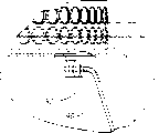
Refer again to Fig. 2 a, electronic installation 12 comprises three blocks of plates that separate, i.e. upper plate 48, middle plate 49 and lower plate 50.Upper plate 48 seals and is connected with electric capacity 20, relay 24 and starter 26 with the upper end 17 of housing 16.On the plate 49, also have a forming open 51 on the middle plate 49 during ballast 22 is installed in, when assembling, the coil 23 of ballast 22 is arranged on wherein.Lower plate 50 (or reflecting plate) is from lower end closed housing 16, and is connected with socket 28.The surface that socket 28 stretches out on the lower plate 50 is preferably by the specular material Miro4 with relative high reflectance
TM(by the Alanod Aluminium-Veredlung GmbH ﹠amp of German Ennepetal; Co. make).Housing 16 also comprises 53 and one the 3rd devices 54 of 52, one second devices of one first device, they have a plurality of coplanar slot, each group groove (52,53,54) in the housing 16 is all with the circumference of annular direction around housing 16, be used for receiving respectively corresponding upper plate 48, plate 49 and lower plate 50, these plates are installed on the housing 16 by described groove.Shown in Fig. 2 a, when central plate 49 and lower plate 50 are assembled on the housing 16, along the through hole 46 therebetween (perhaps between second and the 3rd group of groove 53 and 54) of housing 16 extensions.
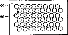
In other embodiment shown in Fig. 1,2a-2b, 3a-3c and the 4a-4b, housing 16 comprises a plurality of illumination holes 55, and they are positioned on the bottom 19 of housing 16 and near lower flange 32, are used to form the lighting pattern that light passes housing 16.With reference to figure 6a-6h, a plurality of illumination holes 55 can form any pattern or characteristic line on housing 16, and only are subjected to the restriction of shape, size and the stability of housing 16.Each through hole 56 also can have multiple shape, include but not limited to square (Fig. 1), circular (Fig. 2,6a and 6h), triangle (Fig. 6 b and 6e), star (Fig. 6 d), cross or plus sige shape (Fig. 6 d), the rectangle (Fig. 6 f-6g) that perhaps has alternative form or other orientation with arbitrary assigned direction.Certainly, should understand fully that every kind of shape can be used with any or multiple other combination of shapes.As mentioned above, a plurality of illumination holes 55 also can comprise a kind of pattern or characteristic line, for example " HOLOPHANE " shown in Fig. 6 h.
Second of lighting device of the present invention is implemented shown in the lighting device among Fig. 4 a-4b 60.Fig. 4 a has represented the stereogram of described second embodiment, and Fig. 4 b has represented its front view.Shown in Fig. 4 a-4b, the invention provides two housing parts of being separated by, lower case part 62 and upper casing part 64.Lower case part 62 comprises bulb 30 and light bulb holder 28, and upper casing part 64 comprises ballast 22 and above-mentioned other heat-sensitive element.As Fig. 4 b institute further represents, housing parts 62 and 64 is spaced from each other, to form institute's calorific requirement isolation, described heat is to be produced by the bulb in the socket 28 (it extends along lower case part 62), bulb is stored in electronic component in the upper casing part 64 away from electric capacity 20 ' and other, comprise ballast, relay, starter 26 ', shown in the section of top housing parts 64.Therefore, owing to these parts 62 and 64 are spaced from each other, so needn't use the through hole 46 shown in Fig. 1 and 2.Housing parts 62 links to each other by Connection Element 66 with 64, and this element 66 can comprise a wires or solid rod, chain, spring or fiberglass kernmantle etc.Certainly, housing parts 62 can link to each other by 67 energisings of suitable lead with 64, and as shown in the figure, lead 67 is around described Connection Element 66.As shown in this paper and first embodiment of the lighting device of describing 10, housing parts 62 and 64 is preferably cylindrical.This lighting device 60 comprises all disclosed advantages of aforementioned illumination apparatus 10.For example, through suitable packing, lighting device 60 can be used as an entire package and transportation, and lower case part 62 is arranged in optical element 68, as described with reference to Fig. 3 a-3c.Lighting device 60 can also comprise the described illumination holes pattern 55 with reference to Fig. 6.
Referring to Fig. 5 a-5d, represented another embodiment of lighting device 80 of the present invention among the figure.Lighting device 80 is similar to first embodiment of lighting device 10; just increased bottom lock device 82; this device 82 normally is installed in the adjusting glass elements 84 (or disk) on the housing 16, to form suitable structural strength and to have defencive function, makes light output quantity maximum simultaneously.This device is to connect by a plurality of lengthwise hanging elements 88 shown in Fig. 5 a-5d, and preferably connect by three small diameter metal wire 90, these metal wires are connected on the disk 84 and are connected in the following manner on the housing 16, that is, make disk 84 centering simultaneously in the lower openings 38 of optical element 32 and on the housing 16.Particularly, shown in Fig. 5 d, be shaped on a plurality of holes 86 on the disk 84, be used for line 90 is connected to disk 84.Therefore, three holes 86 have been represented in the present embodiment, with number (Fig. 5 c and 5d) corresponding to line 90.In addition, shown in Fig. 5 b, line is connected on the housing 16 by holder device 92.Like this, lighting device 80 has the not available advantage of prior art, in prior art, employing be that endless metal belt, inclined-plane or hinge are installed to disk on the Optical devices, thereby stop and disturbed light.By the present invention, owing to adopted line 90, the light that is blocked is minimum or do not have light to be blocked, thereby has improved the efficient of lighting device 80.In addition, the advantage of the embodiment of lighting device noted earlier is present in the present embodiment too, particularly with reference to the disclosed playback of Fig. 3 a-3c with hang those advantages of direction.
Although represent here and described embodiments of the invention, be not that these embodiment represent and described institute of the present invention might form.On the contrary, employed literal only is a descriptive matter in which there rather than restrictive in the specification, should be understood that, under the situation that does not break away from the spirit and scope of the present invention, the present invention can make various deformation.
Claims (21)
1. one kind is suitable for comprising from the suspended electronic installation in position, the crown:
One is roughly columniform housing, and for light source, this housing has enough intensity and heat endurance, and this housing has a longitudinal axis and a plurality of through hole that is used to disperse the heat that is produced by light source,
It is characterized in that this device is suitable for holding and hangs one and is being fit to its also coaxial mounted optics in shape.
2. one kind is suitable for comprising from the suspended lighting device in position, the crown:
An electronic installation, described electronic installation have one and are roughly columniform housing, and for light source, this housing has enough intensity and heat endurance, and this housing has a longitudinal axis and a plurality of through hole that is used to disperse the heat that is produced by light source; With
An optics, the shape of described optics and housing adapts, and suspended from the housing coaxially.
3. one kind is suitable for comprising from the suspended lighting device in position, the crown:
An electronic installation, described electronic installation have a housing, and for light source, this housing has enough intensity and heat endurance, and this housing also has a main housing portion and an outward extending lower edge part; With
An optics, described optics have an inner surface and a upper opening, and this inner surface comprises an end wall that is provided with around upper opening, and upper opening is used to hold described housing and coaxial with it, and upper opening also has the shape corresponding to housing,
It is characterized in that, hanging on the direction, housing stretches out from the upper opening of optics, make lower edge part adjacent end wall also extend around upper opening, with maintenance and suspension optics, wherein, on retracted orientation, the main housing portion of lengthwise housing is positioned at optics, makes the end of lower edge part as upper opening.
4. one kind is suitable for being suspended on indoor lighting device, comprising:
An electronic installation, described electronic installation have a housing, a main housing portion, an outward extending lower edge part and a socket that is used for wherein holding bulb, and described housing has a longitudinal axis; With
An optics, described optics has an inner surface and a upper opening, and this inner surface comprises an end wall that is provided with around upper opening, and upper opening is used to hold described housing and coaxial with it, upper opening also has the shape corresponding to the lengthwise housing
It is characterized in that, hanging on the direction, housing stretches out from the upper opening of optics, make lower edge part adjacent end wall also extend around upper opening, with maintenance and suspension optics, wherein, on retracted orientation, the main housing portion of housing is positioned at optics, makes the end of lower edge part as upper opening.
5. lighting device as claimed in claim 4 is characterized in that housing is columniform, and upper opening has the corresponding annular shape.
6. lighting device as claimed in claim 4, also comprise a bottom lock element, be used to seal the annular lower portion opening of optical element, the bottom lock element is installed on the lengthwise housing by the hanging element that extends between housing and closure elements and be arranged in the optical element.
7. lighting device as claimed in claim 4 also comprises one second housing parts, and described second housing parts separates at the Connection Element and the housing that extend between itself and the housing by one, is used for stored electrons element therein.
8. lighting device as claimed in claim 4 is characterized in that, housing comprises a plurality of through holes that are used to disperse the heat that is produced by bulb.
9. lighting device as claimed in claim 4 is characterized in that housing comprises the illumination holes of a plurality of adjacent bottom marginal portion, is used to constitute light and passes housing and form the outlet that light distributes pattern from bulb.
10. lighting device as claimed in claim 9 is characterized in that, each in a plurality of illumination holes all has the shape of selecting from circle, triangle, star, square, rectangle and criss-cross one group of shape.
11. lighting device as claimed in claim 9 is characterized in that, a plurality of illumination holes have formed predetermined shape, are used to send the light of given shape.
12. lighting device as claimed in claim 4 is characterized in that, on retracted orientation, the lower edge part is a coplane with the lower openings of optical element.
13. lighting device as claimed in claim 4 also comprises a hanging element, described hanging element is installed on the housing, is used for hanging lighting device from crown support member on the suspension direction.
14. one kind is suitable for comprising from the suspended lighting device in position, the crown:
An electronic installation, described electronic installation comprise a circular cylindrical shell body portion, a lower flange part and a socket that is used for holding therein bulb;
A hanging element, described hanging element is installed on the housing parts, is used for from position, crown suspension lighting device; With
An optical element, described optical element have an annular upper portion opening, are used to hold cylindrical housings, and optical element has the upper inside surface of extending around upper opening,
It is characterized in that, hanging on the direction, cylindrical housings is stretched out from the upper opening of Optical devices, makes the lower edge part contact with upper inside surface, to keep and the suspension optical element, and make and between Optical devices and socket, need not relative adjustment, and, wherein, on retracted orientation, the part of cylindrical housings is extended in Optical devices, makes the end of lower edge part as upper opening.
15. lighting device as claimed in claim 14, also comprise a bottom lock element, be used to seal the annular lower portion opening of Optical devices, the bottom lock element is installed on the lengthwise housing by the element that extends between housing and closure elements and be arranged in the optical element.
16. lighting device as claimed in claim 14 also comprises one second housing parts, described second housing parts separates at the Connection Element and the housing that extend between itself and the housing by one.
17. lighting device as claimed in claim 14 is characterized in that, housing comprises a plurality of contiguous ballasts and is used to disperse the through hole of the heat that is produced by bulb.
18. lighting device as claimed in claim 14 is characterized in that, housing comprises the illumination holes at a plurality of adjacent lower edge, is used to constitute pass housing from bulb and form the luminous outlet of pattern.
19. lighting device as claimed in claim 18 is characterized in that, a plurality of illumination holes comprise the shape of selecting from circle, triangle, star, square, rectangle and criss-cross one group of shape.
20. lighting device as claimed in claim 18 is characterized in that, a plurality of illumination holes have formed predetermined shape, are used to send the light of given shape.
21. one kind is suitable for comprising from the suspended lighting device in position, the crown:
An electronic installation, described electronic installation comprise a circular cylindrical shell body portion and a lower flange part; With
An optical element, described optical element have an annular upper portion opening, are used to hold cylindrical housings, and optical element has inner surface, and this inner surface has the upper end wall around upper opening,
It is characterized in that, on the direction of extending fully, cylindrical housings is stretched out from the upper opening of Optical devices, make lower edge partly contiguous and around upper opening, with maintenance and suspension optical element, wherein, on retracted orientation, cylindrical housings at least a portion is extended in Optical devices, makes the end of lower edge part as upper opening.
Applications Claiming Priority (3)
| Application Number | Priority Date | Filing Date | Title |
|---|---|---|---|
| US09/238,699 US6200007B1 (en) | 1999-01-27 | 1999-01-27 | Suspended luminaire assembly |
| US09/238,699 | 1999-01-27 | ||
| US09/238699 | 1999-01-27 |
Publications (2)
| Publication Number | Publication Date |
|---|---|
| CN1264010A CN1264010A (en) | 2000-08-23 |
| CN1107194C true CN1107194C (en) | 2003-04-30 |
Family
ID=22898960
Family Applications (1)
| Application Number | Title | Priority Date | Filing Date |
|---|---|---|---|
| CN99110676A Expired - Fee Related CN1107194C (en) | 1999-01-27 | 1999-07-26 | Hanging-type lighting installation |
Country Status (3)
| Country | Link |
|---|---|
| US (1) | US6200007B1 (en) |
| CN (1) | CN1107194C (en) |
| CA (1) | CA2276884C (en) |
Families Citing this family (12)
| Publication number | Priority date | Publication date | Assignee | Title |
|---|---|---|---|---|
| US6783263B1 (en) * | 1998-03-10 | 2004-08-31 | Paul Andrew Cronk | Adjustable reflector device |
| US6224243B1 (en) | 1999-08-16 | 2001-05-01 | Richard L. Karton | Brooder lamp fixture with power cord suspended in enclosure |
| CA2307469A1 (en) * | 2000-05-03 | 2001-11-03 | Tsung-I Yu | Infrared sensitive electric controlled lamp seat |
| US6578988B2 (en) * | 2001-05-07 | 2003-06-17 | General Electric Company | Apparatus and method for dissipating heat sensitive components in lighting fixtures by dissipating heat therefrom |
| EP1267120A1 (en) * | 2001-06-13 | 2002-12-18 | BÄ*RO GmbH & Co. KG | Interior lighting, in particular to light merchandise display areas |
| US6669159B1 (en) * | 2003-01-07 | 2003-12-30 | Dong Guan Bright Yin Huey Lighting Co., Ltd. | Ceiling fixture |
| DE10346150A1 (en) * | 2003-10-01 | 2005-05-04 | Bae Ro Gmbh & Co Kg | Lighting unit for illumination of goods presentation surface with 3-wire ignition cable between electrical supply unit and main body of lighting unit fitted with lamp socket for gas discharge lamp |
| ITVI20050140A1 (en) * | 2005-05-09 | 2006-11-10 | Beghelli Spa | LIGHTING APPARATUS FOR INDUSTRIAL ENVIRONMENTS WITH SIZE CONTENT |
| EP1793159A1 (en) * | 2005-12-05 | 2007-06-06 | Park, Shi-heung | Infrared lamp apparatus |
| ES1063726Y (en) * | 2006-06-20 | 2007-03-01 | Penin Jose Jorge Fernandez | LOW CONSUMPTION INDUSTRIAL LAMP |
| US9441634B2 (en) | 2013-01-11 | 2016-09-13 | Daniel S. Spiro | Integrated ceiling device with mechanical arrangement for a light source |
| EP2806209B1 (en) | 2013-05-24 | 2019-03-20 | Holophane Europe Ltd. | LED luminaire with multiple vents for promoting vertical ventilation |
Family Cites Families (4)
| Publication number | Priority date | Publication date | Assignee | Title |
|---|---|---|---|---|
| US2171116A (en) * | 1936-10-24 | 1939-08-29 | Henry Hyman | Christmas tree decoration |
| US5121309A (en) * | 1991-01-04 | 1992-06-09 | Holophane Company, Inc. | Industrial luminaire with a quickly installed new and improved optical assembly |
| CA2044886C (en) * | 1991-06-18 | 1995-07-04 | Hsiang Ta Cheng | Projective lamp |
| US5791768A (en) * | 1997-04-17 | 1998-08-11 | Stingray Lighting, Inc. | Dual reflector lighting system |
-
1999
- 1999-01-27 US US09/238,699 patent/US6200007B1/en not_active Expired - Fee Related
- 1999-07-02 CA CA002276884A patent/CA2276884C/en not_active Expired - Fee Related
- 1999-07-26 CN CN99110676A patent/CN1107194C/en not_active Expired - Fee Related
Also Published As
| Publication number | Publication date |
|---|---|
| CN1264010A (en) | 2000-08-23 |
| CA2276884A1 (en) | 2000-07-27 |
| CA2276884C (en) | 2003-01-28 |
| US6200007B1 (en) | 2001-03-13 |
Similar Documents
| Publication | Publication Date | Title |
|---|---|---|
| CN1107194C (en) | Hanging-type lighting installation | |
| US6422720B2 (en) | Retrofit canopy luminaire and method of installing same | |
| US5997158A (en) | Retrofit canopy luminaire and method of installing same | |
| US7524083B2 (en) | Inductive lighting fixture using a reflective vented dome | |
| CN101416273B (en) | Lamp with single-sided socket | |
| US6338564B1 (en) | Optical housing with vertical light source | |
| US20090073680A1 (en) | Inductive lighting for 2' x 2' and 2' x 4' fixtures | |
| CA2623136C (en) | Luminaire optical assembly | |
| CN1111666C (en) | Lighting device | |
| US7914176B2 (en) | Linear light fixture | |
| US20050157498A1 (en) | Luminaire and method for repairing a luminaire | |
| US10422507B2 (en) | Luminaire assembly | |
| US6467927B1 (en) | Overhead industrial light fixture with mounted reflector | |
| CN212319541U (en) | Y-shaped lamp | |
| CN1061172C (en) | Compact fluorescent light bulb | |
| CN1862078A (en) | Lighting appliance with reduced space requirement | |
| US20030165058A1 (en) | Hazardous location induction lighting fixture | |
| CA2363919C (en) | Retrofit canopy luminaire and method of installing same | |
| JP4280906B2 (en) | Lighting device | |
| US6802627B2 (en) | Directional luminaire | |
| CN2248924Y (en) | Energy-saving lamp integrated with transparent cover | |
| CN210567934U (en) | Sealed LED ceiling lamp | |
| CN108758568A (en) | A kind of lamp holder for building combined type outside light | |
| CN209068326U (en) | A kind of arc surface LED downlight | |
| CN2747490Y (en) | Improved fume exhauster |
Legal Events
| Date | Code | Title | Description |
|---|---|---|---|
| C10 | Entry into substantive examination | ||
| SE01 | Entry into force of request for substantive examination | ||
| C06 | Publication | ||
| PB01 | Publication | ||
| C14 | Grant of patent or utility model | ||
| GR01 | Patent grant | ||
| C19 | Lapse of patent right due to non-payment of the annual fee | ||
| CF01 | Termination of patent right due to non-payment of annual fee |