CN110696899A - Food pushing vehicle - Google Patents
Food pushing vehicle Download PDFInfo
- Publication number
- CN110696899A CN110696899A CN201911154932.0A CN201911154932A CN110696899A CN 110696899 A CN110696899 A CN 110696899A CN 201911154932 A CN201911154932 A CN 201911154932A CN 110696899 A CN110696899 A CN 110696899A
- Authority
- CN
- China
- Prior art keywords
- food
- plate
- sides
- base box
- movable
- Prior art date
- Legal status (The legal status is an assumption and is not a legal conclusion. Google has not performed a legal analysis and makes no representation as to the accuracy of the status listed.)
- Pending
Links
Images


Classifications
-
- B—PERFORMING OPERATIONS; TRANSPORTING
- B62—LAND VEHICLES FOR TRAVELLING OTHERWISE THAN ON RAILS
- B62B—HAND-PROPELLED VEHICLES, e.g. HAND CARTS OR PERAMBULATORS; SLEDGES
- B62B5/00—Accessories or details specially adapted for hand carts
- B62B5/0006—Bumpers; Safety devices
-
- A—HUMAN NECESSITIES
- A47—FURNITURE; DOMESTIC ARTICLES OR APPLIANCES; COFFEE MILLS; SPICE MILLS; SUCTION CLEANERS IN GENERAL
- A47B—TABLES; DESKS; OFFICE FURNITURE; CABINETS; DRAWERS; GENERAL DETAILS OF FURNITURE
- A47B31/00—Service or tea tables, trolleys, or wagons
-
- A—HUMAN NECESSITIES
- A47—FURNITURE; DOMESTIC ARTICLES OR APPLIANCES; COFFEE MILLS; SPICE MILLS; SUCTION CLEANERS IN GENERAL
- A47B—TABLES; DESKS; OFFICE FURNITURE; CABINETS; DRAWERS; GENERAL DETAILS OF FURNITURE
- A47B31/00—Service or tea tables, trolleys, or wagons
- A47B2031/002—Catering trolleys
-
- A—HUMAN NECESSITIES
- A47—FURNITURE; DOMESTIC ARTICLES OR APPLIANCES; COFFEE MILLS; SPICE MILLS; SUCTION CLEANERS IN GENERAL
- A47B—TABLES; DESKS; OFFICE FURNITURE; CABINETS; DRAWERS; GENERAL DETAILS OF FURNITURE
- A47B31/00—Service or tea tables, trolleys, or wagons
- A47B2031/008—Outdoor serving carts
Landscapes
- Engineering & Computer Science (AREA)
- Chemical & Material Sciences (AREA)
- Combustion & Propulsion (AREA)
- Transportation (AREA)
- Mechanical Engineering (AREA)
- Handcart (AREA)
Abstract
The invention belongs to the field of food conveying equipment, in particular to a food pushing vehicle, which aims at the problems that the existing food pushing vehicle has poor damping performance, can generate large vibration when moving on a bumpy road surface, easily causes the damage of loaded food due to the vibration generated during the movement, can not ensure the product quality of the food, and has poor practicability, and the invention provides a scheme which comprises a base box and a supporting plate arranged right above the base box, wherein both sides of the top wall of the base box are respectively provided with a rectangular first movable hole, a vertical rectangular movable plate is movably sleeved in the first movable hole, the top end of the movable plate is fixedly connected on the bottom wall of the supporting plate, both sides of the inner bottom wall of the base box are respectively provided with a vertical fixed plate, and the outer rings of the two fixed plates are in clearance fit with a horizontal damping plate, the invention has strong damping performance, and has small vibration during the movement, the loaded food is not easy to be damaged due to vibration generated during moving, the product quality of the food can be ensured, and the practicability is strong.
Description
Technical Field
The invention relates to the technical field of food conveying equipment, in particular to a food pushing vehicle.
Background
The shock absorption performance of current propelling movement food car is relatively poor, can take place great vibrations when moving on the road surface of jolting, leads to the food of loading to damage because of the vibrations that take place when removing easily, can't guarantee the product quality of food, and the practicality is relatively poor.
Disclosure of Invention
The food pushing vehicle provided by the invention solves the problems that the existing food pushing vehicle is poor in damping performance, large vibration can occur when the vehicle moves on a bumpy road surface, loaded food is easily damaged due to the vibration generated during the movement, the product quality of the food cannot be guaranteed, and the practicability is poor.
In order to achieve the purpose, the invention adopts the following technical scheme:
a food pushing vehicle comprises a base box and a supporting plate arranged right above the base box, wherein two sides of the top wall of the base box are respectively provided with a rectangular first movable hole, a vertical rectangular movable plate is movably sleeved in the first movable hole, the top end of the movable plate is fixedly connected to the bottom wall of the supporting plate, two sides of the inner bottom wall of the base box are respectively fixed with a vertical fixed plate, the outer rings of the two fixed plates are in clearance fit with a horizontal damping plate, two sides of the damping plate are respectively provided with a rectangular second movable hole, the bottom end of the movable plate is movably sleeved in the second movable hole, a horizontal supporting rod is fixedly connected between the inner side walls of the two sides of the second movable hole, the movable plates are in clearance fit with the outer rings of the supporting rods, and the inner side walls of the two sides of the second movable hole are respectively connected with second springs with the side walls of the two sides of the movable plate, two that are located the shock attenuation board fixedly connected with dead lever between the lateral wall that the fixed plate is close to each other, the equal clearance fit in both sides of dead lever has the snubber block, two the lateral wall that the fixed plate is close to each other respectively with two the one end that the snubber block was kept away from each other is connected with first spring, the top of snubber block articulates there is the transfer line that is the slope setting, the top of transfer line articulates on the diapire of shock attenuation board.
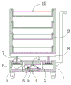
Preferably, the universal wheel is all installed in the four corners of the outer diapire of base case, the welding has the push rod on the lateral wall of base case, the mounting panel has all been welded, two to the both sides of the roof of backup pad be fixed with the year thing case of a plurality of nothing roofs from top to bottom between the mounting panel in proper order.
Preferably, the inner bottom wall of the base box is provided with a sliding groove along the length direction, the two sides of the sliding groove are respectively connected with a sliding block in a sliding manner, and the two damping blocks are respectively fixed at the top ends of the two sliding blocks.
Preferably, the first spring sleeve is arranged on the outer ring of the fixing rod, and the second spring sleeve is arranged on the outer ring of the supporting rod.
Preferably, the width of the first movable hole is matched with the width of the movable plate.
The invention has the beneficial effects that:
through the cooperation of base case, fixed plate, shock attenuation board, dead lever, first spring, transfer line, first movable hole, second movable hole, bracing piece, second spring and backup pad, when the propelling movement food car moves on the road surface of jolting, through the elastic potential energy effect of first spring and second spring, can effectually reduce the vibrations that the propelling movement food car took place, can prevent that the food that loads from damaging because of the vibrations that take place when removing, can guarantee the product quality of food.
The invention has stronger shock absorption performance and smaller shock generated during moving, and the loaded food is not easy to be damaged due to the shock generated during moving, thereby ensuring the product quality of the food and having stronger practicability.
Drawings
Fig. 1 is a schematic structural diagram of a food pushing cart according to the present invention.
Fig. 2 is a partially enlarged view of a portion a in fig. 1.
Fig. 3 is a partially enlarged view of a portion B in fig. 1.
Reference numbers in the figures: 1. a base case; 2. a fixing plate; 3. a damper plate; 4. fixing the rod; 5. a transmission rod; 6. a universal wheel; 7. a movable plate; 8. a support plate; 9. mounting a plate; 10. a carrying box; 11. a damper block; 12. a first spring; 13. a first movable hole; 14. a second movable hole; 15. a support bar; 16. a second spring.
Detailed Description
The technical solutions in the embodiments of the present invention will be clearly and completely described below with reference to the drawings in the embodiments of the present invention, and it is obvious that the described embodiments are only a part of the embodiments of the present invention, and not all of the embodiments.
Referring to fig. 1-3, a food pushing cart comprises a base box 1 and a supporting plate 8 installed right above the base box 1, wherein two sides of the top wall of the base box 1 are respectively provided with a rectangular first movable hole 13, a vertical rectangular movable plate 7 is movably sleeved in the first movable hole 13, the top end of the movable plate 7 is fixedly connected to the bottom wall of the supporting plate 8, two sides of the inner bottom wall of the base box 1 are respectively fixed with a vertical fixed plate 2, the outer rings of the two fixed plates 2 are in clearance fit with a horizontal damping plate 3, two sides of the damping plate 3 are respectively provided with a rectangular second movable hole 14, the bottom end of the movable plate 7 is movably sleeved inside the second movable hole 14, a horizontal supporting rod 15 is fixedly connected between the inner side walls of the two sides of the second movable hole 14, the movable plate 7 is in clearance fit with the outer ring of the supporting rod 15, the inner side walls of the two sides of the second movable hole 14 are respectively connected with the two side walls of, fixedly connected with dead lever 4 between the lateral wall that two fixed plates 2 that are located the below of damper plate 3 are close to each other, the equal clearance fit in both sides of dead lever 4 has snubber block 11, the lateral wall that two fixed plates 2 are close to each other is connected with first spring 12 with the one end that two snubber blocks 11 kept away from each other respectively, the top of snubber block 11 articulates there is the transfer line 5 that is the slope setting, the top of transfer line 5 articulates on damper plate 3's diapire.
The spout has been seted up along length direction on the interior diapire of base case 1, and the equal sliding connection in both sides of spout has the slider, and two snubber blocks 11 are fixed respectively on the top of two sliders.
The first spring 12 is sleeved on the outer ring of the fixing rod 4, and the second spring 16 is sleeved on the outer ring of the supporting rod 15.
The width of the first movable hole 13 is adapted to the width of the movable plate 7.
Example (b): the push rod is pushed, the whole food pushing vehicle can be pushed, when the food pushing vehicle moves on a bumpy road, large vibration can occur, namely, the object carrying box 10, the mounting plate 9 and the supporting plate 8 can vibrate, when the supporting plate 8 vibrates in a horizontal direction, the supporting plate 8 can continuously move left and right, namely, the movable plate 7 can continuously move left and right, namely, the second spring 16 can continuously stretch and rapidly tend to return under the action of elastic potential energy of the second spring 16, namely, the supporting plate 8 can rapidly tend to return, namely, the vibration of the supporting plate in the horizontal direction can be effectively reduced, when the supporting plate 8 vibrates in a vertical direction, the supporting plate 8 can continuously lift, namely, the movable plate 7, the supporting rod 15 and the damping plate 3 can continuously lift, namely, the top ends of the two transmission rods 5 can continuously lift, can make the bottom of two transfer lines 5 keep away from each other promptly, be close to each other, can make two snubber blocks 1 continuous each other keep away from promptly, be close to each other, can make second spring 16 constantly stretch out and draw back promptly, elastic potential energy effect through second spring 16, can make second spring 16 constantly stretch out and draw back and tend to the return rapidly, can make the fly leaf 7, bracing piece 15 and damper plate 3 and backup pad 8 rapidly tend to the return, can effectually reduce backup pad 8 along vertical direction's vibrations, vibrations that backup pad 8 takes place when removing through effectual reduction propelling movement food car, the vibrations of food when can effectually reducing the propelling movement food car and removing, the vibrations that can effectually avoid food to damage because of the vibrations that take place when removing.
The invention has stronger shock absorption performance and smaller shock generated during moving, and the loaded food is not easy to be damaged due to the shock generated during moving, thereby ensuring the product quality of the food and having stronger practicability.
In the description of the present invention, it is to be understood that the terms "center", "longitudinal", "lateral", "length", "width", "thickness", "upper", "lower", "front", "rear", "left", "right", "vertical", "horizontal", "top", "bottom", "inner", "outer", "clockwise", "counterclockwise", and the like, indicate orientations and positional relationships based on those shown in the drawings, and are used only for convenience of description and simplicity of description, and do not indicate or imply that the equipment or element being referred to must have a particular orientation, be constructed and operated in a particular orientation, and thus, should not be considered as limiting the present invention.
Furthermore, the terms "first", "second" and "first" are used for descriptive purposes only and are not to be construed as indicating or implying relative importance or implicitly indicating the number of technical features indicated. Thus, a feature defined as "first" or "second" may explicitly or implicitly include one or more of that feature. In the description of the present invention, "a plurality" means two or more unless specifically defined otherwise.
The above description is only for the preferred embodiment of the present invention, but the scope of the present invention is not limited thereto, and any person skilled in the art should be considered to be within the technical scope of the present invention, and the technical solutions and the inventive concepts thereof according to the present invention should be equivalent or changed within the scope of the present invention.
Claims (5)
1. A food pushing vehicle comprises a base box (1) and a supporting plate (8) installed right above the base box (1), and is characterized in that rectangular first movable holes (13) are formed in two sides of the top wall of the base box (1), a vertical rectangular movable plate (7) is movably sleeved in the first movable holes (13), the top end of the movable plate (7) is fixedly connected to the bottom wall of the supporting plate (8), vertical fixed plates (2) are fixed to two sides of the inner bottom wall of the base box (1), horizontal damping plates (3) are in clearance fit with the outer rings of the two fixed plates (2), rectangular second movable holes (14) are formed in two sides of the damping plates (3), the bottom end of the movable plate (7) is movably sleeved inside the second movable holes (14), and a horizontal supporting rod (15) is fixedly connected between the inner side walls of the two sides of the second movable holes (14), the utility model discloses a damping device, including fly leaf (7), fixed plate (2), damping plate (3), fixed plate (11), fly leaf (7) clearance fit, the outer lane of fly leaf (7) clearance fit at bracing piece (15), the both sides inside wall of second activity hole (14) respectively with the both sides lateral wall of fly leaf (7) is connected with second spring (16), is located two of damping plate (3) below fixedly connected with dead lever (4) between the lateral wall that fixed plate (2) are close to each other, the equal clearance fit in both sides of dead lever (4) has snubber block (11), two the lateral wall that fixed plate (2) are close to each other respectively with two the one end that snubber block (11) kept away from each other is connected with first spring (12), the top of snubber block (11) articulates there is transfer line (5) that the slope.
2. The food cart as claimed in claim 1, wherein universal wheels (6) are mounted at four corners of the outer bottom wall of the base box (1), push rods are welded on the outer side wall of the base box (1), mounting plates (9) are welded on two sides of the top wall of the supporting plate (8), and a plurality of carrier boxes (10) without top walls are sequentially fixed between the two mounting plates (9) from top to bottom.
3. The food cart as claimed in claim 1, wherein a sliding groove is formed in the inner bottom wall of the base box (1) along the length direction, sliding blocks are slidably connected to two sides of the sliding groove, and the two damping blocks (11) are respectively fixed to the top ends of the two sliding blocks.
4. The cart for pushing food as claimed in claim 1, wherein the first spring (12) is sleeved on the outer ring of the fixing rod (4), and the second spring (16) is sleeved on the outer ring of the supporting rod (15).
5. The cart for pushing food as claimed in claim 1, wherein the width of said first movable hole (13) is adapted to the width of said movable plate (7).
Priority Applications (1)
| Application Number | Priority Date | Filing Date | Title |
|---|---|---|---|
| CN201911154932.0A CN110696899A (en) | 2019-11-22 | 2019-11-22 | Food pushing vehicle |
Applications Claiming Priority (1)
| Application Number | Priority Date | Filing Date | Title |
|---|---|---|---|
| CN201911154932.0A CN110696899A (en) | 2019-11-22 | 2019-11-22 | Food pushing vehicle |
Publications (1)
| Publication Number | Publication Date |
|---|---|
| CN110696899A true CN110696899A (en) | 2020-01-17 |
Family
ID=69206546
Family Applications (1)
| Application Number | Title | Priority Date | Filing Date |
|---|---|---|---|
| CN201911154932.0A Pending CN110696899A (en) | 2019-11-22 | 2019-11-22 | Food pushing vehicle |
Country Status (1)
| Country | Link |
|---|---|
| CN (1) | CN110696899A (en) |
Cited By (1)
| Publication number | Priority date | Publication date | Assignee | Title |
|---|---|---|---|---|
| CN112874641A (en) * | 2021-03-31 | 2021-06-01 | 丹阳市华富机械有限公司 | Turnover mechanism for automobile cab |
-
2019
- 2019-11-22 CN CN201911154932.0A patent/CN110696899A/en active Pending
Cited By (1)
| Publication number | Priority date | Publication date | Assignee | Title |
|---|---|---|---|---|
| CN112874641A (en) * | 2021-03-31 | 2021-06-01 | 丹阳市华富机械有限公司 | Turnover mechanism for automobile cab |
Similar Documents
| Publication | Publication Date | Title |
|---|---|---|
| CN210876686U (en) | Processing dust cleaning device of loader transaxle | |
| CN203777177U (en) | A damping type first-aid stretcher trolley with a transfer structure | |
| CN110696899A (en) | Food pushing vehicle | |
| CN211109144U (en) | Container for road transportation | |
| CN211269332U (en) | Intelligent compact shelf with anti-wheel-falling track device | |
| CN207725293U (en) | A kind of bearing type shipping vehicle shock-absorbing device | |
| CN105438046A (en) | Carriage and dump truck | |
| CN213799715U (en) | Protection device for transportation of highway upright post pipe | |
| CN210956343U (en) | Box transformer convenient to remove | |
| CN221736103U (en) | Tool car for overhauling automobile | |
| CN207578368U (en) | A kind of car door assembly material frame | |
| CN221661463U (en) | Anti-jolt logistics transport case | |
| CN214876676U (en) | Knuckle conveyer | |
| CN215154921U (en) | Rural commodity circulation conveyer | |
| CN215807346U (en) | Be used for intelligent security patrol equipment | |
| CN217261631U (en) | Power accessory conveyer | |
| CN221214086U (en) | Folding box transfer trolley | |
| CN117799527B (en) | Traffic monitoring rod carrying trailer | |
| CN219857027U (en) | Vehicle-mounted storage device for trailer accessories | |
| CN216066309U (en) | Butt joint auxiliary device for assembling light rail box body | |
| CN219567444U (en) | Conversion device of engineering service vehicle | |
| CN220430213U (en) | Transfer trolley | |
| CN213228692U (en) | Plastic product turnover device | |
| CN203485965U (en) | Inner plate fixing device of vehicle door inner plate transfer trolley | |
| CN221585400U (en) | Underground unmanned ore transport vehicle |
Legal Events
| Date | Code | Title | Description |
|---|---|---|---|
| PB01 | Publication | ||
| PB01 | Publication | ||
| WD01 | Invention patent application deemed withdrawn after publication | ||
| WD01 | Invention patent application deemed withdrawn after publication |
Application publication date: 20200117 |