CN110694846A - Coating device convenient to carry out spraying to object of different shapes - Google Patents
Coating device convenient to carry out spraying to object of different shapes Download PDFInfo
- Publication number
- CN110694846A CN110694846A CN201911105457.8A CN201911105457A CN110694846A CN 110694846 A CN110694846 A CN 110694846A CN 201911105457 A CN201911105457 A CN 201911105457A CN 110694846 A CN110694846 A CN 110694846A
- Authority
- CN
- China
- Prior art keywords
- box
- paint
- cleaning
- fixed
- different shapes
- Prior art date
- Legal status (The legal status is an assumption and is not a legal conclusion. Google has not performed a legal analysis and makes no representation as to the accuracy of the status listed.)
- Withdrawn
Links
Images

Classifications
-
- B—PERFORMING OPERATIONS; TRANSPORTING
- B05—SPRAYING OR ATOMISING IN GENERAL; APPLYING FLUENT MATERIALS TO SURFACES, IN GENERAL
- B05B—SPRAYING APPARATUS; ATOMISING APPARATUS; NOZZLES
- B05B16/00—Spray booths
- B05B16/20—Arrangements for spraying in combination with other operations, e.g. drying; Arrangements enabling a combination of spraying operations
-
- B—PERFORMING OPERATIONS; TRANSPORTING
- B05—SPRAYING OR ATOMISING IN GENERAL; APPLYING FLUENT MATERIALS TO SURFACES, IN GENERAL
- B05B—SPRAYING APPARATUS; ATOMISING APPARATUS; NOZZLES
- B05B13/00—Machines or plants for applying liquids or other fluent materials to surfaces of objects or other work by spraying, not covered by groups B05B1/00 - B05B11/00
- B05B13/02—Means for supporting work; Arrangement or mounting of spray heads; Adaptation or arrangement of means for feeding work
- B05B13/0221—Means for supporting work; Arrangement or mounting of spray heads; Adaptation or arrangement of means for feeding work characterised by the means for moving or conveying the objects or other work, e.g. conveyor belts
-
- B—PERFORMING OPERATIONS; TRANSPORTING
- B05—SPRAYING OR ATOMISING IN GENERAL; APPLYING FLUENT MATERIALS TO SURFACES, IN GENERAL
- B05B—SPRAYING APPARATUS; ATOMISING APPARATUS; NOZZLES
- B05B13/00—Machines or plants for applying liquids or other fluent materials to surfaces of objects or other work by spraying, not covered by groups B05B1/00 - B05B11/00
- B05B13/02—Means for supporting work; Arrangement or mounting of spray heads; Adaptation or arrangement of means for feeding work
- B05B13/04—Means for supporting work; Arrangement or mounting of spray heads; Adaptation or arrangement of means for feeding work the spray heads being moved during spraying operation
- B05B13/0405—Means for supporting work; Arrangement or mounting of spray heads; Adaptation or arrangement of means for feeding work the spray heads being moved during spraying operation with reciprocating or oscillating spray heads
- B05B13/041—Means for supporting work; Arrangement or mounting of spray heads; Adaptation or arrangement of means for feeding work the spray heads being moved during spraying operation with reciprocating or oscillating spray heads with spray heads reciprocating along a straight line
-
- B—PERFORMING OPERATIONS; TRANSPORTING
- B05—SPRAYING OR ATOMISING IN GENERAL; APPLYING FLUENT MATERIALS TO SURFACES, IN GENERAL
- B05B—SPRAYING APPARATUS; ATOMISING APPARATUS; NOZZLES
- B05B15/00—Details of spraying plant or spraying apparatus not otherwise provided for; Accessories
-
- B—PERFORMING OPERATIONS; TRANSPORTING
- B05—SPRAYING OR ATOMISING IN GENERAL; APPLYING FLUENT MATERIALS TO SURFACES, IN GENERAL
- B05B—SPRAYING APPARATUS; ATOMISING APPARATUS; NOZZLES
- B05B15/00—Details of spraying plant or spraying apparatus not otherwise provided for; Accessories
- B05B15/20—Arrangements for agitating the material to be sprayed, e.g. for stirring, mixing or homogenising
- B05B15/25—Arrangements for agitating the material to be sprayed, e.g. for stirring, mixing or homogenising using moving elements, e.g. rotating blades
-
- B—PERFORMING OPERATIONS; TRANSPORTING
- B05—SPRAYING OR ATOMISING IN GENERAL; APPLYING FLUENT MATERIALS TO SURFACES, IN GENERAL
- B05B—SPRAYING APPARATUS; ATOMISING APPARATUS; NOZZLES
- B05B15/00—Details of spraying plant or spraying apparatus not otherwise provided for; Accessories
- B05B15/50—Arrangements for cleaning; Arrangements for preventing deposits, drying-out or blockage; Arrangements for detecting improper discharge caused by the presence of foreign matter
- B05B15/55—Arrangements for cleaning; Arrangements for preventing deposits, drying-out or blockage; Arrangements for detecting improper discharge caused by the presence of foreign matter using cleaning fluids
-
- B—PERFORMING OPERATIONS; TRANSPORTING
- B05—SPRAYING OR ATOMISING IN GENERAL; APPLYING FLUENT MATERIALS TO SURFACES, IN GENERAL
- B05B—SPRAYING APPARATUS; ATOMISING APPARATUS; NOZZLES
- B05B16/00—Spray booths
- B05B16/90—Spray booths comprising conveying means for moving objects or other work to be sprayed in and out of the booth, e.g. through the booth
-
- B—PERFORMING OPERATIONS; TRANSPORTING
- B05—SPRAYING OR ATOMISING IN GENERAL; APPLYING FLUENT MATERIALS TO SURFACES, IN GENERAL
- B05D—PROCESSES FOR APPLYING FLUENT MATERIALS TO SURFACES, IN GENERAL
- B05D3/00—Pretreatment of surfaces to which liquids or other fluent materials are to be applied; After-treatment of applied coatings, e.g. intermediate treating of an applied coating preparatory to subsequent applications of liquids or other fluent materials
- B05D3/04—Pretreatment of surfaces to which liquids or other fluent materials are to be applied; After-treatment of applied coatings, e.g. intermediate treating of an applied coating preparatory to subsequent applications of liquids or other fluent materials by exposure to gases
- B05D3/0406—Pretreatment of surfaces to which liquids or other fluent materials are to be applied; After-treatment of applied coatings, e.g. intermediate treating of an applied coating preparatory to subsequent applications of liquids or other fluent materials by exposure to gases the gas being air
- B05D3/0413—Heating with air
-
- B—PERFORMING OPERATIONS; TRANSPORTING
- B08—CLEANING
- B08B—CLEANING IN GENERAL; PREVENTION OF FOULING IN GENERAL
- B08B3/00—Cleaning by methods involving the use or presence of liquid or steam
- B08B3/02—Cleaning by the force of jets or sprays
- B08B3/022—Cleaning travelling work
Abstract
The invention discloses a coating device convenient for spraying objects with different shapes, which comprises a cleaning box, a material conveying hose and a corrugated pipe, wherein a paint spraying box is arranged on the right side of the cleaning box, a second conveyor belt penetrates through the inside of a drying box, a first cleaning liquid box and a second cleaning liquid box are arranged on the upper side of the cleaning box, a first cleaning spray head penetrates through the lower side of the first cleaning liquid box, a water diversion pipe penetrates through the lower side of the second cleaning liquid box, a first supporting plate is placed on the upper side of the first conveyor belt, a storage box is fixed on the upper side of the second supporting plate, a first hydraulic rod is fixed at one end of a first hydraulic cylinder, second hydraulic cylinders are fixed on the front outer wall and the rear outer wall of the cleaning box and the paint spraying box respectively, the coating device convenient for spraying the objects with different shapes is provided with a first fixing plate, and the four first fixing plates can assist in fixing the materials with different shapes, the later stage of being convenient for is sprayed paint to the material of different shapes.
Description
Technical Field
The invention relates to the technical field of coating devices, in particular to a coating device convenient for spraying objects with different shapes.
Background
The spray coating is a coating method in which the coating is applied to the surface of an object to be coated by dispersing the coating into uniform and fine droplets by means of a spray gun or a disc atomizer by means of pressure or centrifugal force. It can be divided into air spraying, airless spraying, electrostatic spraying and various derivatives of the above basic spraying forms, such as high flow low pressure atomized spraying, thermal spraying, automatic spraying, multiple spray groups, etc.
Need wash before spraying paint to the object, need artificially place it inside the spray booth after the washing is accomplished, then just can spray paint the processing, waste time is hard, the paint case sets up one, do not prestore the paint vehicle, after paint uses up, if paint supply untimely, can not continue to spray paint the processing to the object, influence whole spraying paint work and normally go on, can only spray paint to the object of same shape, adaptability is not high, can be infected with paint on the instrument that sprays paint incasement portion used and the spray paint incasement wall after spraying paint to the object, if do not in time handle it, influence the inside finishment of spray paint incasement, if do not use paint for a long time, some paint deposits in the spray paint bottom of the case portion, if do not handle, paint can appear the inhomogeneous situation of paint after spouting through the shower nozzle, influence the quality of spraying paint.
Disclosure of Invention
The invention aims to provide a coating device convenient for spraying objects with different shapes, which solves the problems that the prior art needs to manually convey the objects, wastes time and labor, only one paint box is arranged, paint vehicle is not prestored, the objects with the same shape can be sprayed, the inside of the paint box cannot be tidied, and if the paint is not used for a long time, part of the paint is deposited at the bottom of the paint box, so that the condition of uneven paint can be caused.
In order to achieve the purpose, the invention provides the following technical scheme: a coating device convenient for spraying objects with different shapes comprises a cleaning box, a material conveying hose and a corrugated pipe, wherein the right side of the cleaning box is provided with a paint spraying box, the right side of the paint spraying box is provided with a drying box, the interiors of the cleaning box and the paint spraying box are respectively penetrated by a first conveying belt, the interior of the drying box is penetrated by a second conveying belt, the upper side of the cleaning box is provided with a first cleaning liquid box and a second cleaning liquid box, the left side of the second cleaning liquid box is provided with a first cleaning liquid box, the upper sides of the first cleaning liquid box and the second cleaning liquid box are both penetrated by a water inlet, the lower side of the first cleaning liquid box is penetrated by a first cleaning spray head, the first cleaning spray head is arranged in the cleaning box, the lower side of the second cleaning liquid box is penetrated by a water distribution pipe, the water distribution pipe is arranged in the paint spraying box, a first supporting plate is placed on the upper side of the first conveying belt, and an electric telescopic rod is arranged in, meanwhile, a second supporting plate is fixed on the upper side of the electric telescopic rod, a storage box is fixed on the upper side of the second supporting plate, a first hydraulic cylinder is arranged in the storage box, a first hydraulic rod is fixed at one end of the first hydraulic cylinder, a first fixing plate is fixed at one end of the first hydraulic rod, second hydraulic cylinders are fixed on the front outer wall and the rear outer wall of the cleaning box and the paint spraying box respectively, a second hydraulic rod is fixed at one end of the second hydraulic cylinder, a second fixing plate is fixed at one end of the second hydraulic rod, a second cleaning sprayer penetrates through the lower side of the water distribution pipe, a first paint box is arranged on the right side of the first cleaning liquid box, a paint inlet penetrates through the upper side of the first paint box, a pressure pump is arranged in the first paint box, a second paint box is arranged on the right side of the first paint box, a paint inlet pipe penetrates through the left end of the upper side of the second paint box, and a first driving motor is arranged on the right, advance the inside lug that is provided with of lacquer pipe, and the lug upside has placed the filter screen, first driving motor rotates and is connected with drive gear, and the drive gear downside is fixed with the puddler, and the puddler setting is at the second paint incasement portion simultaneously, second driving motor rotates and is connected with reciprocal lead screw, all run through the air heater with stoving case upside around the clean case, and stoving incasement portion inlays and has electric heating wire, and the clean case front side is fixed with the control box simultaneously.
Preferably, the cleaning box and the paint spraying box are provided with water outlets at the lower sides, and waste liquid boxes are arranged at the lower sides of the water outlets.
Preferably, the upper end in the paint spraying box is provided with a slide way, and the slide way is connected with a slide block in a sliding manner.
Preferably, the first conveyor belt and the second support plate are provided with holes with the same diameter.
Preferably, the number of the first fixing plates is four, the four first fixing plates are enclosed to form a shape like a Chinese character 'hui', and meanwhile, one end of each first fixing plate is provided with an anti-slip pad.
Preferably, the number of the water distribution pipes is three, and four second cleaning nozzles penetrate through the lower sides of the three water distribution pipes at equal distances.
Preferably, one end of the delivery hose is communicated with the pressure pump, the delivery hose is in threaded connection with a threaded fixing piece, and the lower side of the threaded fixing piece is in threaded connection with a paint inlet pipe.
Preferably, one end of the corrugated pipe is communicated with the second paint box, the other end of the corrugated pipe is communicated with the paint sprayer, and a screw nut is fixed on the upper side of the paint sprayer.
Preferably, the screw rod nut is in threaded connection with a reciprocating screw rod, a connecting rod is fixed on the upper side of the screw rod nut, and a sliding block is fixed on the upper side of the connecting rod.
Compared with the prior art, the invention has the beneficial effects that: the coating device is convenient for spraying objects with different shapes,
(1) the cleaning box is arranged, materials directly enter the cleaning box for cleaning and drying before being sprayed with paint, and finally directly enter the paint spraying box for paint spraying treatment, manual carrying is not needed, and time and labor are saved;
(2) the four first fixing plates can be used for auxiliary fixing of materials in different shapes, so that the materials in different shapes can be sprayed at a later stage, and the adaptability of the coating device is improved;
(3) the first cleaning spray head is arranged, after materials are sprayed with paint, cleaning liquid can be sprayed to the inner wall of the paint spraying box and tools inside the paint spraying box under the action of the first cleaning spray head, so that the materials can be cleaned, and the cleanness and tidiness of the inside are ensured;
(4) the first paint box is arranged, and paint can be supplemented timely when the paint supply in the second paint box is not timely due to the first paint box, so that the normal operation of paint spraying is ensured;
(5) be provided with the puddler, when needs use second paint box, the puddler stirs to the puddler is provided with two, shortens the churning time, and is more even with the paint vehicle stirring, ensures the later stage and sprays the quality.
Drawings
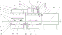
FIG. 1 is a schematic front view of the present invention;
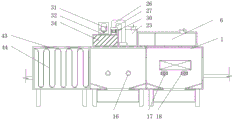
FIG. 2 is a rear view of the present invention;
FIG. 3 is a schematic top view of the present invention;
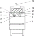
FIG. 4 is a left side view of the present invention;
FIG. 5 is a schematic view of the arrangement of the first paint boxes on the paint spray booth of the present invention;
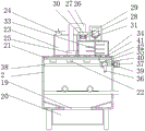
FIG. 6 is a schematic right-view illustration of the arrangement of the first paint tank of the present invention on the paint spray tank;
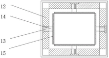
FIG. 7 is a schematic view of a distribution structure of the first hydraulic cylinder in the storage box according to the present invention;
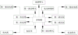
FIG. 8 is a schematic view of the control box according to the present invention.
In the figure: 1. a cleaning box, 2, a paint spraying box, 3, a drying box, 4, a first conveyor belt, 5, a second conveyor belt, 6, a first cleaning liquid box, 7, a water inlet, 8, a first cleaning spray head, 9, a first supporting plate, 10, an electric telescopic rod, 11, a second supporting plate, 12, a storage box, 13, a first hydraulic cylinder, 14, a first hydraulic rod, 15, a first fixing plate, 16, a second hydraulic cylinder, 17, a second hydraulic rod, 18, a second fixing plate, 19, a water outlet, 20, a waste liquid box, 21, a water diversion pipe, 22, a second cleaning spray head, 23, a first paint box, 24, a paint inlet, 25, a pressure pump, 26, a material conveying hose, 27, a threaded fixing part, 28, a paint inlet pipe, 29, a bump, 30, a filter screen, 31, a first driving motor, 32, a driving gear, 33, a stirring rod, 34, a second paint box, 35, a corrugated pipe, 36 and a paint spray head, 37. the cleaning device comprises a screw rod nut 38, a reciprocating screw rod 39, a second driving motor 40, a connecting rod 41, a slideway 42, a sliding block 43, a hot air blower 44, an electric heating wire 45, a control box 46 and a second cleaning liquid box.
Detailed Description
The technical solutions in the embodiments of the present invention will be clearly and completely described below with reference to the drawings in the embodiments of the present invention, and it is obvious that the described embodiments are only a part of the embodiments of the present invention, and not all of the embodiments. All other embodiments, which can be derived by a person skilled in the art from the embodiments given herein without making any creative effort, shall fall within the protection scope of the present invention.
Referring to fig. 1-8, the present invention provides a technical solution: a coating device convenient for coating objects with different shapes is disclosed, as shown in figures 1 and 7, a paint spraying box 2 is arranged on the right side of a cleaning box 1, a drying box 3 is arranged on the right side of the paint spraying box 2, a first conveying belt 4 penetrates through the interiors of the cleaning box 1 and the paint spraying box 2, a second conveying belt 5 penetrates through the interior of the drying box 3, a first cleaning liquid box 6 and a second cleaning liquid box 46 are arranged on the upper side of the cleaning box 1, a first cleaning liquid box 6 is arranged on the left side of the second cleaning liquid box 46, a water inlet 7 penetrates through the upper sides of the first cleaning liquid box 6 and the second cleaning liquid box 46, a first cleaning spray head 8 penetrates through the lower side of the first cleaning liquid box 6, the first cleaning spray head 8 is arranged in the interior of the cleaning box 1, a water diversion pipe 21 penetrates through the lower side of the second cleaning liquid box 46, the water diversion pipe 21 is arranged in the interior of the paint spraying box 2, a first supporting plate 9 is arranged on the upper side of the first, and first backup pad 9 is inside to be provided with electric telescopic handle 10, electric telescopic handle 10 upside is fixed with second backup pad 11 simultaneously, 11 upsides of second backup pad are fixed with storage tank 12, and storage tank 12 is inside to be provided with first pneumatic cylinder 13, first pneumatic cylinder 13 one end is fixed with first hydraulic stem 14, and 14 one end of first hydraulic stem is fixed with first fixed plate 15, first fixed plate 15 is provided with four, and four first fixed plate 15 enclose to close and be "back" font, 15 one end of first fixed plate is provided with the slipmat simultaneously, start first pneumatic cylinder 13 under the effect of control box 45, first pneumatic cylinder 13 drives first fixed plate 15 through first hydraulic stem 14 and stretches out and draws back, just so can fix the object of different shapes, be convenient for the later stage to spray paint the processing to the object of different shapes.
As shown in fig. 1, 2, 3 and 4, a second hydraulic cylinder 16 is fixed on the front and rear outer walls of the cleaning box 1 and the paint spraying box 2, a second hydraulic rod 17 is fixed at one end of the second hydraulic cylinder 16, a second fixing plate 18 is fixed at one end of the second hydraulic rod 17, water outlets 19 are arranged at the lower sides of the cleaning box 1 and the paint spraying box 2, a waste liquid box 20 is arranged at the lower side of the water outlet 19, holes with the same diameter are penetrated through the first conveyor belt 4 and the second support plate 11, after an object is cleaned, a cleaning liquid moves to the first conveyor belt 4 through the holes in the second support plate 11, the cleaning liquid moves downwards to the water outlet 19 through the holes in the first conveyor belt 4, and finally the cleaning liquid is stored in the waste liquid box 20 of the cleaning box 1 through the water outlet 19, so as to treat waste water uniformly at the later stage, a second cleaning nozzle 22 is penetrated through the lower side of the, distributive pipe 21 is provided with threely, and the impartial distance of three distributive pipe 21 downside runs through there are four clean shower nozzles of second 22, twelve clean shower nozzle 22's setting can be with 2 inside instruments of spray paint case and 2 inner walls of spray paint case wash more thoroughly, it is clean to ensure that 2 inside clean and tidy of spray paint case, first clean liquid case 6's right side is provided with first paint box 23, and first paint box 23 upside runs through there is paint inlet 24, first paint box 23 inside is provided with force (forcing) pump 25 simultaneously, conveying hose 26 one end is linked together with force (forcing) pump 25, and conveying hose 26 threaded connection has threaded fastener 27, threaded fastener 27 downside threaded fastener has into lacquer pipe 28 simultaneously.
As shown in fig. 1, 5, 6 and 8, a second paint box 34 is disposed on the right side of the first paint box 23, a paint inlet pipe 28 penetrates through the left end of the upper side of the second paint box 34, a first driving motor 31 is disposed on the right side of the paint inlet pipe 28, a projection 29 is disposed inside the paint inlet pipe 28, a filter screen 30 is disposed on the upper side of the projection 29, the first driving motor 31 is rotatably connected with a driving gear 32, a stirring rod 33 is fixed on the lower side of the driving gear 32, the stirring rod 33 is disposed inside the second paint box 34, one end of a corrugated pipe 35 is communicated with the second paint box 34, the other end of the corrugated pipe 35 is communicated with a paint spray head 36, a lead screw nut 37 is fixed on the upper side of the paint spray head 36, the lead screw nut 37 is in threaded connection with a reciprocating lead screw 38, a connecting rod 40 is fixed on the upper side of the lead screw nut 37, a slide block 42 is fixed on the upper, and the slide 41 is connected with the slide block 42 in a sliding manner, the second driving motor 39 is started under the action of the control box 45, the second driving motor 39 rotates to drive the reciprocating screw rod 38 to rotate, the reciprocating screw rod 38 rotates to drive the screw rod nut 37 to rotate, the screw rod nut 37 moves left and right under the auxiliary action of the connecting rod 40, the slide 41 and the slide block 42, so that the lower paint spray head 36 can be driven to move left and right in a reciprocating manner, so that the paint can be sprayed repeatedly, the paint spraying quality is ensured, the second driving motor 39 is connected with the reciprocating screw rod 38 in a rotating manner, the front and back of the drying box 1 and the upper side of the drying box 3 are both penetrated by hot air blowers 43, an electric heating wire 44 is embedded in the shell of the drying box 3, and the control.
The working principle is as follows: when the coating device convenient for spraying objects with different shapes is used, an external power supply is switched on, water is stored in the first cleaning liquid tank 6 through the water inlet 7 on the upper side of the first cleaning liquid tank 6, paint cleaning liquid is stored in the second cleaning liquid tank 46 through the water inlet 7 on the upper side of the second cleaning liquid tank 46, paint is stored in the first paint tank 23 through the paint inlet 24, the booster pump 25 is started, the paint is sucked into the delivery hose 26 by the booster pump 25, the paint enters the paint inlet pipe 28 through the delivery hose 26, the filter screen 30 in the paint inlet pipe 28 is filtered, the paint liquid is finally stored in the second paint tank 34, the first support plate 9 is placed on the first conveyor belt 4, materials are placed on the second support plate 11, the first hydraulic cylinder 13 is started under the action of the control box 45, the first hydraulic cylinder 13 drives the first fixing plate 15 to stretch through the first hydraulic rod 14, finally, the material is fixed in an auxiliary manner, the first conveyor belt 4 is started, the first conveyor belt 4 transports the material to a required position in the cleaning box 1, the second hydraulic cylinder 16 on the cleaning box 1 is started under the action of the control box 45, the second hydraulic cylinder 16 drives the second fixing plate 18 to move through the second hydraulic rod 17, the first supporting plate 9 is fixed finally, the first cleaning spray head 8 is started, water in the first cleaning liquid box 6 enters the first cleaning spray head 8, the material is cleaned under the action of the first cleaning spray head 8, the cleaned liquid flows onto the first conveyor belt 4 through holes in the second supporting plate 11, the cleaning liquid flows downwards into the water outlet 19 through the holes in the first conveyor belt 4, the cleaning liquid is stored in the waste liquid box 20 on the lower side of the cleaning box 1 through the water outlet 19, the hot air fan 43 on the cleaning box 1 is started under the action of the control box 45, the hot air blower 43 dries the cleaned material, the second hydraulic cylinder 16 is started after drying is completed, the second hydraulic cylinder 16 drives the second fixing plate 18 to move relatively through the second hydraulic rod 17, the second fixing plate 18 is separated from the first supporting plate 9, the dried material is transported to a required position in the paint spraying box 2 under the action of the first conveyor belt 4, the second hydraulic cylinder 16 on the paint spraying box 2 is started under the action of the control box 45, the second hydraulic cylinder 16 drives the second fixing plate 18 to move through the second hydraulic rod 17, finally, the first supporting plate 9 is fixed, the first driving motor 31 is started under the action of the control box 45, the first driving motor 31 rotates to drive the driving gear 32 to rotate, the driving gear 32 rotates to drive the stirring rod 33 to rotate, the stirring rod 33 rotates to drive the paint in the second paint spraying box 34 to be stirred, the second driving motor 39 is started under the action of the control box 45, the second driving motor 39 rotates to drive the reciprocating screw rod 38 to rotate, the reciprocating screw rod 38 rotates to drive the screw rod nut 37 to rotate, the screw rod nut 37 moves left and right under the auxiliary action of the connecting rod 40, the slide rail 41 and the slide block 42, so that the lower paint spray head 36 can be driven to move left and right in a reciprocating manner, the paint spray head 36 is started, the paint enters the paint spray head 36 through the corrugated pipe 35, the paint is sprayed on the material through the paint spray head 36, the second hydraulic cylinder 16 is started after the paint is sprayed, the second hydraulic cylinder 16 drives the second fixing plate 18 to move relatively through the second hydraulic rod 17, the second fixing plate 18 is separated from the first supporting plate 9, the first conveyor belt 4 and the second conveyor belt 5 are started, the material moves rightwards under the action of the first conveyor belt 4 and finally moves onto the second conveyor belt 5, and is conveyed into the drying box 3 under the action of the second conveyor belt, the air heater 43 and the electric heating wire 44 inside the drying box 3 dry the paint, the second cleaning nozzle 22 is started under the action of the control box 45, the cleaning solution enters the second cleaning nozzle 22 through the water distribution pipe 21, the cleaning solution cleans the tools inside the paint spraying box 2 and the inner wall of the paint spraying box 2 through the second cleaning nozzle 22, after the cleaning is completed, the cleaning solution flows to the water outlet 19 on the lower side of the paint spraying box 2 through the holes on the first conveyor belt 4, and is finally stored in the waste water tank 20.
The terms "central," "longitudinal," "lateral," "front," "rear," "left," "right," "vertical," "horizontal," "top," "bottom," "inner," "outer," and the like are used in the orientation or positional relationship indicated in the drawings for simplicity of description only and are not intended to indicate or imply that the referenced devices or elements must be in a particular orientation, constructed and operative in a particular orientation, and are not to be considered limiting of the claimed invention.
Although the present invention has been described in detail with reference to the foregoing embodiments, it will be apparent to those skilled in the art that various changes in the embodiments and/or modifications of the invention can be made, and equivalents and modifications of some features of the invention can be made without departing from the spirit and scope of the invention.
Claims (9)
1. The utility model provides a coating device convenient to carry out spraying to object of different shapes, includes clean case (1), defeated material hose (26) and bellows (35) its characterized in that: the cleaning box is characterized in that a paint spraying box (2) is arranged on the right side of the cleaning box (1), a drying box (3) is arranged on the right side of the paint spraying box (2), a first conveying belt (4) penetrates through the insides of the cleaning box (1) and the paint spraying box (2), a second conveying belt (5) penetrates through the inside of the drying box (3), a first cleaning liquid box (6) and a second cleaning liquid box (46) are arranged on the upper side of the cleaning box (1), a first cleaning liquid box (6) is arranged on the left side of the second cleaning liquid box (46), a water inlet (7) penetrates through the upside of the first cleaning liquid box (6) and the second cleaning liquid box (46), a first cleaning spray nozzle (8) penetrates through the lower side of the first cleaning liquid box (6), the first cleaning spray nozzle (8) is arranged inside the cleaning box (1), a water diversion pipe (21) penetrates through the lower side of the second cleaning liquid box (46), and the water diversion pipe (21) is arranged inside the paint spraying box (2), a first supporting plate (9) is placed on the upper side of the first conveying belt (4), an electric telescopic rod (10) is arranged inside the first supporting plate (9), a second supporting plate (11) is fixed on the upper side of the electric telescopic rod (10), a storage box (12) is fixed on the upper side of the second supporting plate (11), a first hydraulic cylinder (13) is arranged inside the storage box (12), a first hydraulic rod (14) is fixed at one end of the first hydraulic cylinder (13), a first fixing plate (15) is fixed at one end of the first hydraulic rod (14), second hydraulic cylinders (16) are fixed on the front outer wall and the rear outer wall of the cleaning box (1) and the paint spraying box (2), a second hydraulic rod (17) is fixed at one end of the second hydraulic cylinder (16), a second fixing plate (18) is fixed at one end of the second hydraulic rod (17), and a second cleaning sprayer (22) penetrates through the lower side of the water distribution pipe (21), the right side of first cleaning solution case (6) is provided with first paint case (23), and first paint case (23) upside runs through into lacquer mouth (24), and first paint case (23) inside is provided with force (forcing) pump (25) simultaneously, first paint case (23) right side is provided with second paint case (34), and second paint case (34) upside left end has run through into lacquer pipe (28), advances lacquer pipe (28) right side simultaneously and is provided with first driving motor (31), it is provided with lug (29) to advance lacquer pipe (28) inside, and filter screen (30) have been placed to lug (29) upside, first driving motor (31) rotate and are connected with drive gear (32), and drive gear (32) downside is fixed with puddler (33), and puddler (33) set up inside second paint case (34) simultaneously, second driving motor (39) rotate and are connected with reciprocal lead screw (38), air heater (43) have all been run through with stoving case (3) upside around clean case (1), and stoving case (3) shell inside inlays and has electric heating wire (44), and clean case (1) front side is fixed with control box (45) simultaneously.
2. A painting apparatus for facilitating painting of objects of different shapes according to claim 1, wherein: cleaning box (1) and spray paint case (2) downside all are provided with delivery port (19), and delivery port (19) downside is provided with waste liquid case (20).
3. A painting apparatus for facilitating painting of objects of different shapes according to claim 1, wherein: slide (41) have been seted up to the inside upper end of spray booth (2), and slide (41) sliding connection has slider (42).
4. A painting apparatus for facilitating painting of objects of different shapes according to claim 1, wherein: holes with the same diameter penetrate through the first conveying belt (4) and the second supporting plate (11).
5. A painting apparatus for facilitating painting of objects of different shapes according to claim 1, wherein: the number of the first fixing plates (15) is four, the four first fixing plates (15) are enclosed to form a shape like a Chinese character 'hui', and meanwhile, one end of each first fixing plate (15) is provided with an anti-slip pad.
6. A painting apparatus for facilitating painting of objects of different shapes according to claim 1, wherein: the number of the water distribution pipes (21) is three, and four second cleaning nozzles (22) penetrate through the lower sides of the three water distribution pipes (21) at equal distances.
7. A painting apparatus for facilitating painting of objects of different shapes according to claim 1, wherein: one end of the material conveying hose (26) is communicated with the pressure pump (25), the material conveying hose (26) is in threaded connection with a threaded fixing piece (27), and the lower side of the threaded fixing piece (27) is in threaded connection with a paint inlet pipe (28).
8. A painting apparatus for facilitating painting of objects of different shapes according to claim 1, wherein: one end of the corrugated pipe (35) is communicated with the second paint box (34), the other end of the corrugated pipe (35) is communicated with the paint spray head (36), and meanwhile, a lead screw nut (37) is fixed on the upper side of the paint spray head (36).
9. A painting apparatus for facilitating painting of objects of different shapes according to claim 8, wherein: the screw rod nut (37) is in threaded connection with a reciprocating screw rod (38), a connecting rod (40) is fixed on the upper side of the screw rod nut (37), and a sliding block (42) is fixed on the upper side of the connecting rod (40).
Priority Applications (1)
| Application Number | Priority Date | Filing Date | Title |
|---|---|---|---|
| CN201911105457.8A CN110694846A (en) | 2019-11-13 | 2019-11-13 | Coating device convenient to carry out spraying to object of different shapes |
Applications Claiming Priority (1)
| Application Number | Priority Date | Filing Date | Title |
|---|---|---|---|
| CN201911105457.8A CN110694846A (en) | 2019-11-13 | 2019-11-13 | Coating device convenient to carry out spraying to object of different shapes |
Publications (1)
| Publication Number | Publication Date |
|---|---|
| CN110694846A true CN110694846A (en) | 2020-01-17 |
Family
ID=69205246
Family Applications (1)
| Application Number | Title | Priority Date | Filing Date |
|---|---|---|---|
| CN201911105457.8A Withdrawn CN110694846A (en) | 2019-11-13 | 2019-11-13 | Coating device convenient to carry out spraying to object of different shapes |
Country Status (1)
| Country | Link |
|---|---|
| CN (1) | CN110694846A (en) |
Cited By (7)
| Publication number | Priority date | Publication date | Assignee | Title |
|---|---|---|---|---|
| CN111299052A (en) * | 2020-03-02 | 2020-06-19 | 江苏松源机械制造有限公司 | Coating device for paint spraying chamber |
| CN111558490A (en) * | 2020-05-25 | 2020-08-21 | 滁州市天悦塑胶制品有限公司 | Automatic spraying equipment |
| CN111604196A (en) * | 2020-06-02 | 2020-09-01 | 吕子乒 | Mechanical automatic spraying equipment |
| CN111644316A (en) * | 2020-06-17 | 2020-09-11 | 李登进 | Automatic coating equipment for battery processing |
| CN112007806A (en) * | 2020-08-31 | 2020-12-01 | 深圳市深羽电子科技有限公司 | Bluetooth headset shell spraying device |
| CN112191424A (en) * | 2020-09-24 | 2021-01-08 | 邱海姑 | Surface oil attaching device for machining mechanical parts |
| CN112934565A (en) * | 2021-01-27 | 2021-06-11 | 滁州市友邦涂装有限公司 | Automatic spraying device for paint layer on surface of panel of washing machine |
-
2019
- 2019-11-13 CN CN201911105457.8A patent/CN110694846A/en not_active Withdrawn
Cited By (9)
| Publication number | Priority date | Publication date | Assignee | Title |
|---|---|---|---|---|
| CN111299052A (en) * | 2020-03-02 | 2020-06-19 | 江苏松源机械制造有限公司 | Coating device for paint spraying chamber |
| CN111299052B (en) * | 2020-03-02 | 2021-04-23 | 江苏松源机械制造有限公司 | Coating device for paint spraying chamber |
| CN111558490A (en) * | 2020-05-25 | 2020-08-21 | 滁州市天悦塑胶制品有限公司 | Automatic spraying equipment |
| CN111604196A (en) * | 2020-06-02 | 2020-09-01 | 吕子乒 | Mechanical automatic spraying equipment |
| CN111604196B (en) * | 2020-06-02 | 2021-07-23 | 吕子乒 | Mechanical automatic spraying equipment |
| CN111644316A (en) * | 2020-06-17 | 2020-09-11 | 李登进 | Automatic coating equipment for battery processing |
| CN112007806A (en) * | 2020-08-31 | 2020-12-01 | 深圳市深羽电子科技有限公司 | Bluetooth headset shell spraying device |
| CN112191424A (en) * | 2020-09-24 | 2021-01-08 | 邱海姑 | Surface oil attaching device for machining mechanical parts |
| CN112934565A (en) * | 2021-01-27 | 2021-06-11 | 滁州市友邦涂装有限公司 | Automatic spraying device for paint layer on surface of panel of washing machine |
Similar Documents
| Publication | Publication Date | Title |
|---|---|---|
| CN110694846A (en) | Coating device convenient to carry out spraying to object of different shapes | |
| CN110773365B (en) | Multi-angle automatic paint spraying equipment for machining mechanical parts | |
| CN208586865U (en) | A kind of building coating spraying machine | |
| WO2019091079A1 (en) | Efficient spraying machine | |
| CN110369200A (en) | A kind of intelligent flush coater of adjustable spray range | |
| CN212856343U (en) | Spraying machine | |
| CN209523441U (en) | A kind of building water-proof paint spray equipment | |
| US1829831A (en) | Pipe painting apparatus | |
| CN110548638A (en) | Intelligent coating integrated equipment for aluminum-plastic panel processing | |
| CN108855664A (en) | Coating sprays drying unit | |
| CN211660344U (en) | Automobile plate paint spraying and drying device | |
| CN207655397U (en) | A kind of spray equipment with dust reduction capability | |
| CN211678445U (en) | Coating device convenient to carry out spraying to object of different shapes | |
| CN205816031U (en) | A kind of spray-painting plant of drying function | |
| CN209452089U (en) | Spray equipment is used in a kind of production of musical box | |
| CN210138780U (en) | Coating equipment with drying and waste gas treatment functions | |
| CN110605208A (en) | Intelligent coating processing equipment with automatic cleaning spray head | |
| CN106311531A (en) | Brazing flux spraying device for air cooling island pipes | |
| CN208213575U (en) | A kind of coating equipment | |
| CN106670979B (en) | online surface processing device | |
| CN215235238U (en) | Cosmetics container spraying dust blocking device | |
| CN211678454U (en) | Spraying device for automotive interior gear panel | |
| CN210815943U (en) | Surface paint spraying device for plastic pipe processing | |
| CN210333135U (en) | Sound-insulation anticorrosive wood floor paint spraying device | |
| CN211275178U (en) | Intelligent coating processing equipment with automatic cleaning spray head |
Legal Events
| Date | Code | Title | Description |
|---|---|---|---|
| PB01 | Publication | ||
| PB01 | Publication | ||
| SE01 | Entry into force of request for substantive examination | ||
| SE01 | Entry into force of request for substantive examination | ||
| WW01 | Invention patent application withdrawn after publication |
Application publication date: 20200117 |
|
| WW01 | Invention patent application withdrawn after publication |