Ink-jet printer adopts the ink jet-print head that is installed on the scanning balladeur train usually, and described balladeur train is followed the usual practice and moved around as print media such as paper.Printhead comprises a spout part over against print media.The response of this spout part is from the signal of the control system that links to each other with print system, is used for optionally ink droplet jet to print media.Described balladeur train drives injector and scans to print delegation along print media.Then, medium is sent to and allows injector print another row.In this manner, the ink droplet of row has constituted image and the literal on the print media continuously.
It is very important that the image that forms on print media has high print quality.To a great extent, print quality depends on the correct work of printhead.Printhead generally includes an internal container, this container and injector fluid communication.For the proper operation of spout part, key factor be ink in the internal container with respect to atmospheric fluid pressure, this pressure is called gauge pressure.Pressure-regulating device is usually included in the printhead, is used for controlling the gauge pressure of internal container.
In the past, some printers employings can be from the independent print cartridge of changing on the printhead.After the print cartridge emptying, this print cartridge can be moved out of and change.Use the print cartridge of this independent replacing to make to print and proceed to print head longevity most the time.
Some printers are arranged also by adopting the print cartridge of " not on balladeur train ", wherein print cartridge is positioned at outside the scanning balladeur train.These not the print cartridge on balladeur train usually pass through pipeline and fluid communication with the printhead internal container.Adopt this not print cartridge on balladeur train can alleviate balladeur train weight, make balladeur train more compact, required mobile power is littler, thereby available littler balladeur train motor drives sledge movements.The 5th, 650, No. 811 patent has been described a kind of like this structure, and promptly it comprises a print cartridge that links to each other with pipeline, and described pipeline links to each other with the pressure regulator of printhead more successively.This pressure regulator has guaranteed that the spout part of printhead receives ink at suitable pressures.
In order to make adjuster controlled pressure correctly, print system adopts the print cartridge that the pressure ink can be provided to printhead.In order to guarantee that printhead correctly works, be very important to the printhead ink delivery with the pressure that is equal to, or greater than the printhead operating pressure.After this, adjuster is regulated the fluid pressure that is supplied to spout part, correctly works to guarantee printhead.Adopt adjuster and supply pressure ink can be adapted to multiple design form, layout and environmental factor, such as the relative altitude of pressure drop amount, printhead and the ink of supplying and atmospheric variation etc.
Used in the past ink-jet print system is multiple former thereby employing pressure ink.The ink jet component of working pressure ink or the example of ink-jet system are described in the 4th, 568, No. 954 United States Patent (USP)s of the 4th, 558, No. 326 of people such as Kimura and Rosback to some extent.
A problem of pressure ink ink box is that internal pressure is to the influence at the print cartridge material.The most handy cheap material manufacturing of removable print cartridge, for example plastics.And the internal pressure that continues can make these material generation permanent deformations.If this distortion is enough big, print cartridge can't be used.The print cartridge example that can't use that how to become is, this distortion has hindered the print cartridge receiving slit that print cartridge is put into ink-jet print system.
For print cartridge pressurized and the print cartridge that do not use in the ink-jet print system on balladeur train, there are needs always, promptly these print cartridges should be able to use under indeformable or the situation of leaking.In addition, these print cartridges answer cost low to reduce the price of ink apparatus.
Fig. 1 is the schematic diagram that comprises the ink-jet print system 10 of print cartridge 12 of the present invention, and described print cartridge is used for sending the pressure ink to printhead 14.Print system 10 comprises a pressure source 16 that is used for print cartridge 12 pressurizations.Corresponding to exert pressure, print cartridge 12 provides the pressure ink by pipeline 18 to printhead 14.Under the control of printer electronics 20, printhead 14 optionally is sprayed on ink on the medium (not shown).
Pressure source 16 links to each other with print cartridge 12 by pressure pipeline 22, makes air-flow flow to print cartridge 12 so that print cartridge 12 is pressurizeed from pressure source 16.Pressure source 16 response is from the signal of printer electronics control appliance 20, for example supplies compression gases such as air to pressure pipeline 22.Pressure pipeline 22 links to each other with gas vent 24, and this outlet successively with print cartridge 12 with gas feed 26 link to each other.Gas feed 26 links to each other with pressure chamber 28, and described pressure chamber is surrounded by the inner surface 30 of print cartridge 12.Print cartridge 12 comprises an exhaust apparatus 32, and this device has been set up gas channel between pressure chamber 28 and atmosphere outside, makes when arbitrary moment that pressure differential is arranged between pressure chamber 28 and atmosphere outside, pressure chamber 28 exhaust continuously.
Print cartridge 12 is supplied inks by fluid pipeline 18 to printhead 14.Print cartridge 12 comprises the ink 34 of supplying usefulness, and these inks can fluidly link to each other with liquid outlet 36.Liquid outlet 36 is connected with liquid-inlet 38, and liquid-inlet 38 links to each other with first end of fluid pipeline 18 successively.Second end of fluid pipeline 18 links to each other with printhead 14.
The ink that printhead 14 receives from pipeline 18, and optionally ink is ejected on the medium (not shown).Printhead 14 comprises that one is regulated part 40, an internal container 42 and a spout part 44.Regulate the fluid pressure in part 40 adjustings or the control internal container 42.In one embodiment, adjuster comprises a valve 40a who links to each other with pipeline 18.Pressure in the adjuster 40 response internal containers 42 changes and opens or shut off valve 40a, to keep the suitable gauge pressure in the internal container 42.Liquid in the internal container 42 communicates with spout part 44.The signal from printer electronics 20 that spout part 44 responses receive optionally is ejected into ink on the medium (not shown).
Fig. 2 is the schematic diagram of an embodiment of print system 10.Print system 10 comprises a Support for impression mechanism 46, and this frame 46 comprises one or more print cartridge 12 of the present invention, and they are slidably mounted on one of a plurality of receiving slits 48.Embodiment shown in Figure 2 is configured to hold the form of four print cartridges 12, and each print cartridge contains a kind of different color.Under four look printing situations, each in these four print cartridges 12 all has a kind of different ink color, such as blue or green, Huang, magenta and black ink.In four kinds of inks each all is supplied to one or more printhead 14, and optionally ink is ejected into successively on the print media such as paper etc.Support for impression mechanism 46 also comprises the control panel 50 of an operation that is used to control print system 10 and the media slot 52 of output print medium.
Preferred print cartridge 12 of the present invention is to printhead 14 supply pressure inks.Print cartridge 12 in the present embodiment is slidably mounted in the receiving slit 48.Receiving slit 48 is made of pair of sidewalls 54 at least in part.Under print cartridge 12 deformable situations, the pressure in the print cartridge 12 can make pair of sidewalls 56 produce outside expansion or projection.If print cartridge 12 long-time pressurizeds, then print cartridge 12 can permanent deformation.If this distortion is very violent, will hinder print cartridge 12 and be installed between the sidewall 54, make the insertion of print cartridge 12 and shift out all very difficult.Exhaust apparatus 32 of the present invention can guarantee that internal pressure descends, to prevent the permanent deformation of print cartridge 12.
Fig. 3 A has represented a preferred embodiment of the print cartridge 12 cut open along 3A-3A among Fig. 2.Print cartridge 12 shown in Fig. 3 A comprises a support 58, a deformable container 60 and a pressurized tank 62.Referring to Fig. 1, similar element is represented with similar sequence number.But the embodiment of print cartridge 12 shown in Figure 1 has the ink that directly contacts with the outer wall of print cartridge 12.On the contrary, Fig. 3 A has represented to have the print cartridge 12 of the deformable container 60 that contains ink and centered on by pressurized tank 62.In addition, be different from Fig. 1, the print cartridge of form has adopted support 58 shown in Fig. 3 A.
Support 58 has multiple function.It comprises liquid outlet 36, and forms fluid connection between liquid outlet 36 and deformable container 60.Support 58 comprises gas feed 26, and this import 26 communicates with pressure chamber 28 liquid.Pressure chamber 28 is formed by the outer surface of deformable container 60 and the inner surface 30 of pressurized tank 62.
Deformable container 60 is a deformable films bag that contains the ink 34 of supplying usefulness preferably.One end of this bag has opening, bag sealing surfaces 64 sealings on this opening and the support 58.
In a preferred embodiment, pressurized tank 62 is ampuliform seals of being made by polyethylene.Can be designed to provide the pressure that approximates 2PSI (pound/square inch), the ink 34 of supply usefulness is exerted pressure.But the lasting pressure in the chamber 28 can cause pressurized tank 62 permanent deformations.When in the process of using print system during supercharging, sidewall 54 (see figure 2)s form certain support and are beneficial to pressurized tank 62 and avoid producing permanent deformation.Pressurized tank 62 is installed to the position on contiguous wiper seal surface 66 on the support 58.In a preferred embodiment, the sealing between pressurized tank 62 and the support 58 is formed by O shape circle 68.
Print cartridge 12 is suitable for being removably mounted in the receiving slit 48 (Fig. 2).After print cartridge 12 installs, shown in the enlarged drawing of Fig. 1 and Fig. 3 B, set up the liquids and gases annexation.Fig. 3 B has represented the such as shown in Figure 3A liquid outlet 36 and the gas feed 26 that link to each other with print system 10.The liquid-inlet 36 that links to each other with print cartridge 12 and with liquid-inlet 38 that receiving slit 48 links to each other between set up the liquid annexation, and between the printing ink 34 of supply and printhead 14, form fluid connection.In this embodiment, liquid outlet 36 comprises a liquid dividing plate 70 that is used for seal fluid outlet 36.Liquid-inlet 38 comprises a hollow needle 72, and the liquid in this pin 72 links to each other with fluid pipeline 18, and described fluid pipeline 18 is connected with print system 10.
When print cartridge 12 is installed in the receiving slit 48, the gas feed 26 that links to each other with print cartridge 12 and with gas vent 24 that print system 10 links to each other between set up annexation, between pressure source 16 and pressure chamber 28, to form fluid connection.In this embodiment, gas feed 26 comprises a gas barrier 74.Gas vent 24 comprises a hollow needle 76 that links to each other with pressure pipeline 22.
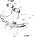
4A with the aid of pictures again, it has represented the preferred embodiment of support 58.Except above-mentioned functions is provided, this support also comprises an exhaust apparatus 32.Exhaust apparatus 32 is communicated with between the outer surface and pressure chamber 28 of support 58 (Fig. 3 A).
Fig. 4 B is the figure that the part of support 58 is clipped, and has shown the preferred embodiment of exhaust apparatus 32 on cross section.Exhaust apparatus 32 comprises a porous or gas osmotic component 78, and this element 78 is connected between pressure chamber 28 and the outside atmosphere.In a preferred embodiment, exhaust apparatus 32 comprises the inner surface 82 extended housings 80 from support 58.Multihole device 78 is supported by housing 80.
Multihole device 78 is preferably by the moulding of injection moulding porous polyethylene.An example of this material is the commodity POREX by name by the Porex Technologies company manufacturing of Fairburn Georgia
TMMaterial.Mainly by the pore size decision of material, secondly the compression degree by the multihole device 78 that is compressed by housing 80 determines the flow behavior of multihole device 78.Along with the increase of capillary dimensions, flow restriction and fluid resistance reduce.Above-mentioned compression effects is to reduce capillary dimensions, increases flow resistance.In a preferred embodiment, multihole device 78 has the capillary dimensions of 18-40 micron.
In a preferred embodiment, exhaust apparatus 32 provides the air velocity of about 3cc/min (cubic centimetre per minute) especially, this flow velocity be STP (normal temperature and normal pressure) down and the pressure reduction between pressure chamber 28 and the outside atmosphere measure when being 2.5PSI (pound per square inch).But, depending on the sensitivity of volume of a container, 62 pairs of permanent deformations of container tank and the speed that pneumatic supply 16 (as shown in Figure 1) is exerted pressure to pressure chamber 28, preferred flow velocity may be different.
In a preferred embodiment, multihole device 78 has formed liquid and has passed obstacle between chamber 28 and the outside atmosphere.This is will to add such as common absorbing material such as powdered clay in the plastics that are used to form multihole device 78 and realize.When liquid contact multihole device 78, absorbing material expands, and blocks the pore in the multihole device 78.
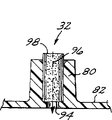
Fig. 4 C and 4D have shown the sectional view of the exhaust apparatus 32 of unassembled and assembled state respectively.Shown in Fig. 4 C, exhaust apparatus 32 comprises a cylindrical composite hole 84, and this hole 84 has one than major diameter part 86 and a smaller diameter portion 88.Formed a step 90 radially than changeover portion between major diameter part and the smaller diameter portion.The large-diameter portion branch comprises a starting taper part 92.
Shown in Fig. 4 C, exhaust apparatus 32 forms by cylindrical multihole device 78 is inserted in the composite holes 84.Starting taper part 92 helps multihole device 78 to import major diameter part 86.Multihole device 78 is pressed into composite holes, when guide end 94 contacts radially step 90 till.After multihole device 78 was installed to major diameter part 86, multihole device 78 had been guaranteed to form firm sealing by radial compression between the inwall of multihole device 78 and major diameter part 86.
Fig. 4 D has represented the state of exhaust apparatus 32 after assembling.Multihole device 78 has formed gas channel 96 between pressure chamber 28 and outside atmosphere.The small diameter portion 88 of composite holes 84 has constituted connected relation between the guide end 94 of multihole device 78 and outside atmosphere.The end 98 of multihole device 78 extends in the chamber 28.Housing 80 extends also and exceeds inner surface 82 certain distances, a certain amount ofly gathers fluid and can not stop up exhaust apparatus 32 so that exhaust apparatus 32 holds along inner surface 82.
As a kind of replacement form, multihole device 78 can be made by sintering metal.Sintering metal will produce similar effect and the similar manner discussed with reference Fig. 4 C and 4D is used.Sintering metal has the aperture that gas or air can pass, but has stoped liquid under the pressure that increases being inversely proportional to hole dimension.
Exhaust apparatus 32 also can be made one or more and have controlled opening size and be communicated with pressure chamber 28 and labyrinth type of outside atmosphere (spirality, snakelike, broken line shape etc.) passage.The quantity of passage, opening size, length and curved geometric can be adjusted, to form air-flow and the liquid flowing resistance of giving sizing.
The exhaust apparatus of putting in the support 58 32 is described below with reference to Fig. 4 A-D.Exhaust apparatus also can be put into other position of print cartridge 12, and forms gas channel between pressure chamber 28 and outside atmosphere.For example, Fig. 1 has shown that threading is such as the exhaust apparatus 32 in the outer wall of pressurized tank 62 print cartridges such as grade 12.
The step of making print cartridge 12 comprises assembling print cartridge element and to the print cartridge filling ink.Filling step is usually by realizing to liquid outlet 36 supply inks.Referring to Fig. 1, can see that when adding ink, the air in the chamber 28 is compressed and pressurized.Under the effect of exhaust apparatus 32, these air can be discharged.Like this, the advantage of exhaust apparatus 32 is that exhaust apparatus 32 can discharge any residual pressure in initial ink filling process.
After print cartridge 12 assembled, pressure chamber 28 had the pressure that equates with outside atmosphere usually.If print cartridge 12 is by aircraft dispatch or be sent to the area with higher height above sea level, will produce pressure differential between pressure chamber 28 and the outside atmosphere.In common print cartridge course of conveying, this pressure differential may reach 5PSI or higher.Even this pressure differential only continues 2-3 hour, the wall of pressurized tank 62 just may permanent deformation.If this distortion is enough big, may hinders print cartridge 12 and pack in the receiving slit 48 (Fig. 2).By the pressure in the release pressure jar 62, exhaust apparatus 32 of the present invention has been avoided this permanent deformation.
The minimal flow speed of avoiding this permanent deformation to need being used for exhaust apparatus 32.For example, minimal flow speed is approximately per minute 1cc (cubic centimetre) air, and this flow velocity at STP (normal temperature and normal pressure) down and pressure differential (between pressure chamber 28 and the outside atmosphere) measurement when be 2.5PSI (pound per square inch).For the small container with less elastic pressure jar, this minimum of a value can be the air (similarity condition) of per minute 0.1cc or still less.Minimal flow speed depends on different factors usually, for example container volume, pressurized tank material etc.
During work, print cartridge 12 is installed to earlier in the receiving slit 48, makes liquid outlet 36 engage with liquid-inlet 38, sets up the ink 34 and the relation of the fluid connection between the fluid pipeline 18 of supply usefulness.Also gas feed 26 can be connected the connected relation between build-up pressure pipeline 22 and the pressure chamber 28 with the air outlet slit 24 of print system when inserting print cartridge 12.
At first, print cartridge 12 is in off working state, and at this moment ink can suitably not be supplied to print system 10 under the pressure.In order to reach duty, pressurized tank 62 must be forced into a suitable value.Pressure source or air pump 16 begin by pressure pipeline 22 to pressure chamber 28 supply gas, to form positive inside gauge pressure in pressure chamber 28.Simultaneously, exhaust apparatus 32 is from pressure chamber 28 release pressures.Importantly exhaust apparatus 32 release pressure very slowly makes pressure source 16 exert pressure to chamber 28 with acceptable speed.
This pressure request that adds is that exhaust apparatus 32 is provided with maximum flow rate.For example, maximum flow rates is per minute 5cc (air under STP) when inner gauge pressure is 2.5PSI.But according to time requirement that print cartridge 12 is exerted pressure and the flow rate that produced by pressure source 16, acceptable flow rate can be per minute 50cc or higher (air under STP) when inner gauge pressure is 2.5PSI.
In case inner gauge pressure (in the pressure chamber 28) reaches preset range, then print cartridge 12 is in running order, and described preset range refers to working pressure range.Print system 10 optionally provides power on signal to printhead 14 then, optionally to spray ink to medium.For exemplary systems, this gauge pressure should be 0.5 to 3.0 pound per square inch.In a preferred embodiment, this gauge pressure should be in 1.0 to 2.0 pounds scope per square inch.Ink flows out from ink supply unit 34, through fluid line 18 toward print head 14, to fill with printhead 14 once more.For print system shown in Figure 1, each printhead 14 comprises a pressure regulator 40, is used to regulate or adjust the pressure between pipeline 18 and the container 42, makes spout part 44 can carry out appropriate operation.
In print procedure, pressure chamber 28 pressure inside remain in the predetermined pressure range, to guarantee reaching required ink flow rate from the ink of ink supply unit 34 toward print head 14.This is to realize by the pressure of regulating pump 16 transmission.Another replacement form can be to open and close pump 16 to keep suitable pressure.
After printing end, pump 16 cuts out.At this moment, exhaust apparatus 32 makes the pressure in the pressure chamber 28 discharge.But the pressure changing down is very low, if making to print in special time begins once more, then the inside gauge pressure of pressure chamber 28 will be in sufficiently high value to begin printing.Like this, preferably flow rate is enough low, makes after pump cuts out, and pressure chamber 28 is depressed at half worksheet at least and kept for 5 seconds.But,, preferably in 5 hours, discharge the operating pressure of half at least for fear of pressurized tank 62 distortion.
When print cartridge 12 was pulled down from print system, exhaust apparatus made and to prevent print cartridge 12 above-mentioned distortion takes place by the print cartridge release of pressure.Like this, before print cartridge used up, print cartridge can be removed and replace, and can not produce the problem that is taken place when print cartridge 12 inserted print system 10 once more.