CN110691908B - parked components - Google Patents
parked components Download PDFInfo
- Publication number
- CN110691908B CN110691908B CN201880037452.3A CN201880037452A CN110691908B CN 110691908 B CN110691908 B CN 110691908B CN 201880037452 A CN201880037452 A CN 201880037452A CN 110691908 B CN110691908 B CN 110691908B
- Authority
- CN
- China
- Prior art keywords
- parking
- support structure
- coupling arrangement
- parking assembly
- assembly
- Prior art date
- Legal status (The legal status is an assumption and is not a legal conclusion. Google has not performed a legal analysis and makes no representation as to the accuracy of the status listed.)
- Active
Links
- 238000010168 coupling process Methods 0.000 claims abstract description 57
- 230000008878 coupling Effects 0.000 claims abstract description 56
- 238000005859 coupling reaction Methods 0.000 claims abstract description 56
- 238000003032 molecular docking Methods 0.000 claims abstract description 24
- 238000000034 method Methods 0.000 claims abstract description 16
- 238000009434 installation Methods 0.000 claims description 46
- 230000007704 transition Effects 0.000 claims description 46
- 229910000831 Steel Inorganic materials 0.000 claims description 6
- 239000010959 steel Substances 0.000 claims description 6
- 239000013013 elastic material Substances 0.000 claims description 4
- 238000012423 maintenance Methods 0.000 description 7
- 230000000284 resting effect Effects 0.000 description 5
- 230000004048 modification Effects 0.000 description 4
- 238000012986 modification Methods 0.000 description 4
- 230000008901 benefit Effects 0.000 description 3
- 238000010276 construction Methods 0.000 description 3
- 239000000463 material Substances 0.000 description 3
- 229920001971 elastomer Polymers 0.000 description 2
- 239000003550 marker Substances 0.000 description 2
- 229920001084 poly(chloroprene) Polymers 0.000 description 2
- 239000011253 protective coating Substances 0.000 description 2
- 230000008439 repair process Effects 0.000 description 2
- 238000005253 cladding Methods 0.000 description 1
- 239000011248 coating agent Substances 0.000 description 1
- 238000000576 coating method Methods 0.000 description 1
- 238000005553 drilling Methods 0.000 description 1
- 230000000694 effects Effects 0.000 description 1
- 230000007613 environmental effect Effects 0.000 description 1
- 230000002349 favourable effect Effects 0.000 description 1
- 239000000835 fiber Substances 0.000 description 1
- 239000006260 foam Substances 0.000 description 1
- 238000004519 manufacturing process Methods 0.000 description 1
- 229920003023 plastic Polymers 0.000 description 1
- 239000004033 plastic Substances 0.000 description 1
- 230000008569 process Effects 0.000 description 1
- 230000001681 protective effect Effects 0.000 description 1
- 125000006850 spacer group Chemical group 0.000 description 1
- 238000003860 storage Methods 0.000 description 1
- 239000000758 substrate Substances 0.000 description 1
Images


Classifications
-
- F—MECHANICAL ENGINEERING; LIGHTING; HEATING; WEAPONS; BLASTING
- F03—MACHINES OR ENGINES FOR LIQUIDS; WIND, SPRING, OR WEIGHT MOTORS; PRODUCING MECHANICAL POWER OR A REACTIVE PROPULSIVE THRUST, NOT OTHERWISE PROVIDED FOR
- F03D—WIND MOTORS
- F03D80/00—Details, components or accessories not provided for in groups F03D1/00 - F03D17/00
- F03D80/50—Maintenance or repair
-
- F—MECHANICAL ENGINEERING; LIGHTING; HEATING; WEAPONS; BLASTING
- F05—INDEXING SCHEMES RELATING TO ENGINES OR PUMPS IN VARIOUS SUBCLASSES OF CLASSES F01-F04
- F05B—INDEXING SCHEME RELATING TO WIND, SPRING, WEIGHT, INERTIA OR LIKE MOTORS, TO MACHINES OR ENGINES FOR LIQUIDS COVERED BY SUBCLASSES F03B, F03D AND F03G
- F05B2230/00—Manufacture
- F05B2230/60—Assembly methods
- F05B2230/61—Assembly methods using auxiliary equipment for lifting or holding
-
- F—MECHANICAL ENGINEERING; LIGHTING; HEATING; WEAPONS; BLASTING
- F05—INDEXING SCHEMES RELATING TO ENGINES OR PUMPS IN VARIOUS SUBCLASSES OF CLASSES F01-F04
- F05B—INDEXING SCHEME RELATING TO WIND, SPRING, WEIGHT, INERTIA OR LIKE MOTORS, TO MACHINES OR ENGINES FOR LIQUIDS COVERED BY SUBCLASSES F03B, F03D AND F03G
- F05B2240/00—Components
- F05B2240/90—Mounting on supporting structures or systems
- F05B2240/95—Mounting on supporting structures or systems offshore
-
- Y—GENERAL TAGGING OF NEW TECHNOLOGICAL DEVELOPMENTS; GENERAL TAGGING OF CROSS-SECTIONAL TECHNOLOGIES SPANNING OVER SEVERAL SECTIONS OF THE IPC; TECHNICAL SUBJECTS COVERED BY FORMER USPC CROSS-REFERENCE ART COLLECTIONS [XRACs] AND DIGESTS
- Y02—TECHNOLOGIES OR APPLICATIONS FOR MITIGATION OR ADAPTATION AGAINST CLIMATE CHANGE
- Y02E—REDUCTION OF GREENHOUSE GAS [GHG] EMISSIONS, RELATED TO ENERGY GENERATION, TRANSMISSION OR DISTRIBUTION
- Y02E10/00—Energy generation through renewable energy sources
- Y02E10/70—Wind energy
- Y02E10/72—Wind turbines with rotation axis in wind direction
-
- Y—GENERAL TAGGING OF NEW TECHNOLOGICAL DEVELOPMENTS; GENERAL TAGGING OF CROSS-SECTIONAL TECHNOLOGIES SPANNING OVER SEVERAL SECTIONS OF THE IPC; TECHNICAL SUBJECTS COVERED BY FORMER USPC CROSS-REFERENCE ART COLLECTIONS [XRACs] AND DIGESTS
- Y02—TECHNOLOGIES OR APPLICATIONS FOR MITIGATION OR ADAPTATION AGAINST CLIMATE CHANGE
- Y02E—REDUCTION OF GREENHOUSE GAS [GHG] EMISSIONS, RELATED TO ENERGY GENERATION, TRANSMISSION OR DISTRIBUTION
- Y02E10/00—Energy generation through renewable energy sources
- Y02E10/70—Wind energy
- Y02E10/727—Offshore wind turbines
-
- Y—GENERAL TAGGING OF NEW TECHNOLOGICAL DEVELOPMENTS; GENERAL TAGGING OF CROSS-SECTIONAL TECHNOLOGIES SPANNING OVER SEVERAL SECTIONS OF THE IPC; TECHNICAL SUBJECTS COVERED BY FORMER USPC CROSS-REFERENCE ART COLLECTIONS [XRACs] AND DIGESTS
- Y02—TECHNOLOGIES OR APPLICATIONS FOR MITIGATION OR ADAPTATION AGAINST CLIMATE CHANGE
- Y02P—CLIMATE CHANGE MITIGATION TECHNOLOGIES IN THE PRODUCTION OR PROCESSING OF GOODS
- Y02P70/00—Climate change mitigation technologies in the production process for final industrial or consumer products
- Y02P70/50—Manufacturing or production processes characterised by the final manufactured product
Landscapes
- Engineering & Computer Science (AREA)
- Life Sciences & Earth Sciences (AREA)
- Sustainable Development (AREA)
- Sustainable Energy (AREA)
- Chemical & Material Sciences (AREA)
- Combustion & Propulsion (AREA)
- Mechanical Engineering (AREA)
- General Engineering & Computer Science (AREA)
- Wind Motors (AREA)
Abstract
Description
技术领域technical field
本发明描述了一种停放组件,该停放组件被实现成暂时地支撑风力涡轮机的工作平台。本发明还描述了一种在这样的停放组件上停放工作平台方法。The present invention describes a parking assembly implemented as a working platform for temporarily supporting a wind turbine. The present invention also describes a method of parking a work platform on such a parking assembly.
背景技术Background technique
海上设施(诸如风力涡轮机)经常暴露于恶劣的风和天气条件。通常,海上设施(诸如风力涡轮机)被安装在支撑结构上,该支撑结构诸如为在单桩和风力涡轮机的塔架之间具有过渡件的单桩。过渡件通常具有固定平台以提供安全的着陆区域并且使得能够接近风力涡轮机的技术设备。在其寿命期间,风力涡轮机通常需要被维护,并且技师可能需要从外部接近到叶片和/或塔架。为了维护和维修塔架和叶片,工作平台通常被运输到风力涡轮机位置,在此其被联接到提升设备(诸如起重机)并且沿着塔架的外部被提升,以致工人能够从外部接近转子叶片和塔架。这样的工作平台的示例是维护平台FFB360。由于具有挑战性的环境条件,诸如大风、漂移或波浪,将工作平台运输到风力涡轮机是一个关键程序。工作平台能够从船取下并且被直接地安装到风力涡轮机的塔架。在已知方法中,工作平台能够在一天结束时或在恶劣天气条件的情况下被拆下并再次转移到船。在恶劣天气条件的情况下,这能够导致问题,而且能够是昂贵的。通常,在同一风力涡轮机处需要一个工作平台工作几天甚至几周。为了避免过多的船租赁成本,暂时的停放平台能够被安装在风力涡轮机的过渡件上。停放平台为工作平台和技师/维护人员提供了安全的着陆区域并且允许工作平台在维修操作之间保持在风力涡轮机处。该方法的另一优点在于,工作平台的复杂的拆卸程序仅需要被执行一次。Offshore installations, such as wind turbines, are often exposed to severe wind and weather conditions. Typically, offshore installations, such as wind turbines, are mounted on a support structure, such as a monopile with a transition piece between the monopile and the tower of the wind turbine. The transition piece usually has a fixed platform to provide a safe landing area and to enable access to the technical equipment of the wind turbine. During its lifetime, wind turbines often need to be maintained and technicians may need external access to the blades and/or tower. For maintenance and repair of the tower and blades, the work platform is usually transported to the wind turbine location, where it is coupled to lifting equipment (such as a crane) and lifted along the exterior of the tower so that workers can access the rotor blades and tower. An example of such a work platform is the maintenance platform FFB360. Transporting work platforms to wind turbines is a critical procedure due to challenging environmental conditions such as high winds, drift or waves. The working platform can be removed from the vessel and mounted directly to the tower of the wind turbine. In the known method, the working platform can be dismantled and transferred to the ship again at the end of the day or in case of bad weather conditions. In the event of severe weather conditions, this can cause problems and can be expensive. Often, a working platform is required to work for days or even weeks at the same wind turbine. In order to avoid excessive boat rental costs, a temporary parking platform can be installed on the transition piece of the wind turbine. The parking platform provides a safe landing area for the work platform and technician/maintenance personnel and allows the work platform to remain at the wind turbine between maintenance operations. Another advantage of this method is that the complex disassembly procedure of the work platform only needs to be performed once.
对于已知类型的停放平台的安装,需要特殊的适配器,该适配器必须针对工作平台和过渡件二者被定制设计。此外,在安装停放平台之前可能需要拆下和修改过渡件的栏杆或其它部分。通常,结合过渡件的必要修改的为各种不同过渡件定制的适配器的生产是耗时的过程,该过程增加了海上风力涡轮机的总体维修成本。For the installation of known types of docking platforms, special adapters are required, which must be custom designed for both the work platform and the transition piece. Additionally, railings or other parts of the transition piece may need to be removed and modified prior to installation of the parking platform. Typically, the production of custom adapters for various different transition pieces, incorporating the necessary modifications of the transition pieces, is a time-consuming process that adds to the overall maintenance cost of an offshore wind turbine.
发明内容SUMMARY OF THE INVENTION
因此本发明的目标是提供一种克服了上文讨论的问题的用于海上设施的工作平台的停放平台。It is therefore an object of the present invention to provide a docking platform for a working platform of an offshore installation which overcomes the problems discussed above.
该目标是通过本发明的停放组件以及本发明的停放海上设施的工作平台的方法来实现的。This object is achieved by the parking assembly of the invention and the method of parking a working platform of an offshore installation of the invention.
根据本发明,停放组件被实现成承载海上设施的工作平台。本发明的停放组件包括:支撑结构,其具有被布置成接收工作平台的水平部分;以及联接布置,其被实现成将支撑结构可拆卸地固定到海上设施的直立元件,其中,联接布置包括被实现成水平地环绕直立元件的至少一个带。水平部分被实现成为工作平台提供在任何类型的海上设施上的暂时竖立(stand),并且还允许存储此类平台几周或几个月。水平部分被实现成不管直立元件的设计或构造特征如何均突出超过直立元件的外边缘。停放组件的联接布置被实现成将停放组件可拆卸地固定到任何海上设施的直立元件而不需要对直立元件进行任何修改。联接布置被实现成水平地环绕海上设施的直立元件。According to the invention, the docking assembly is realized as a working platform carrying the offshore installation. The docking assembly of the present invention comprises: a support structure having a horizontal portion arranged to receive a work platform; and a coupling arrangement realized as an upright element for removably securing the support structure to the offshore installation, wherein the coupling arrangement comprises being At least one band is implemented to surround the upstanding element horizontally. The horizontal section is realized as a working platform to provide a temporary stand on any type of offshore installation and also to allow storage of such platforms for weeks or months. The horizontal portion is implemented to protrude beyond the outer edge of the upstanding element regardless of the design or construction features of the upstanding element. The coupling arrangement of the docking assembly is realized to removably secure the docking assembly to the upright element of any offshore installation without requiring any modification to the upright element. The coupling arrangement is implemented to horizontally surround the upright elements of the offshore installation.
本发明的停放组件的优点在于,停放组件普遍地适用于任何类型的海上设施而不需要修改工作平台或海上设施。停放组件能够例如与具有不同设计和构造特征的海上风力涡轮机的过渡件一起使用。此外,联接布置被实现成将停放组件可拆卸地固定到海上设施的直立元件而不需要附加的适配器或紧固件。An advantage of the docking assembly of the present invention is that the docking assembly is universally applicable to any type of offshore installation without requiring modification of the work platform or offshore installation. The parking assembly can be used, for example, with transition pieces for offshore wind turbines having different design and construction features. Furthermore, the coupling arrangement is realized to removably secure the docking assembly to the upright element of the offshore installation without the need for additional adapters or fasteners.
本发明的停放组件适合用于风力涡轮机的叶片和塔架的维护和维修平台的不同类型和实施例,诸如上文提到的FFB360工作平台。当然,本发明的停放组件能够用于可以使用其它种类的工作平台的任何种类的海上设施,诸如变电站或者油或气体钻探设施。The parking assembly of the present invention is suitable for different types and embodiments of maintenance and repair platforms for blades and towers of wind turbines, such as the FFB360 work platform mentioned above. Of course, the parking assembly of the present invention can be used in any kind of offshore installation where other kinds of work platforms may be used, such as substations or oil or gas drilling installations.
根据本发明,停放海上设施的工作平台的方法包括以下步骤:将这样的停放组件暂时地固定到海上设施的直立元件;将工作平台降低到停放组件的支撑结构;以及将工作平台可拆卸地固定到停放组件的支撑结构。According to the present invention, a method of parking a working platform of an offshore installation comprises the steps of: temporarily securing such a parking assembly to an upright element of the offshore installation; lowering the working platform to the supporting structure of the parking assembly; and removably securing the working platform to the support structure for the parking assembly.
该本发明的方法的优点在于,停放组件能够相对容易地固定到直立元件,而不需要部件(诸如过渡件的栏杆)的任何耗时的拆下。此外,如上文所提到地,本发明的方法能够与工作平台的不同类型和实施例一起使用。以此方式,本发明的方法能够显著地降低海上设施的总体维修成本。An advantage of the method of the present invention is that the parking assembly can be fixed to the upright element relatively easily without any time-consuming dismantling of parts such as rails of the transition piece. Furthermore, as mentioned above, the method of the present invention can be used with different types and embodiments of work platforms. In this way, the method of the present invention can significantly reduce the overall maintenance cost of the offshore installation.
由优选实施方案给出本发明的特别有利的实施例和特征,如下文描述中所揭示的。不同实施方案的特征可以适当地组合以给出本文中没有描述的另外实施例。Particularly advantageous examples and features of the invention are given by the preferred embodiments, as disclosed in the following description. Features of different embodiments may be combined as appropriate to give additional examples not described herein.
如上文所述提到地,本发明的停放组件能够与任何种类的海上设施一起使用。在下文中,在不以任何方式限制本发明的情况下,可以假定海上设施是海上风力涡轮机,对于该海上风力涡轮机,直立元件是支撑机舱的塔架。As mentioned above, the docking assembly of the present invention can be used with any kind of offshore installation. In the following, without limiting the invention in any way, it may be assumed that the offshore installation is an offshore wind turbine, for which the upright element is the tower supporting the nacelle.
本发明的停放组件的支撑结构包括实现风力涡轮机的工作平台的暂时支撑的所有器具,并且也可以包括便于停放组件或工作平台的安装和/或拆卸的另外部件。支撑结构优选地被实现成使得水平部分突出超过过渡件的栏杆,该栏杆的高度通常约为150厘米或更高。The support structure of the parking assembly of the present invention includes all the means to effect temporary support of the working platform of the wind turbine, and may also include additional components that facilitate the installation and/or removal of the parking assembly or the working platform. The support structure is preferably implemented such that the horizontal portion protrudes beyond the railing of the transition piece, which is typically about 150 cm or more in height.
在下文中,术语“停放组件”和“停放平台”可以被看作是同义词并且可以被互换地使用。In the following, the terms "parking assembly" and "parking platform" may be considered synonymous and may be used interchangeably.
在本发明的停放组件的优选实施例中,联接布置的带包括弹性材料。例如,带能够由弹性材料制成,该材料可以以平坦条带的形式编织或者以绳的形式扭曲。带的长度能够根据风力涡轮机的塔架的直径进行选择。优选地,带的长度足以环绕具有15米或更大的周长的塔架。带的直径和断裂强度能够根据工作平台的预期负载应力进行选择。例如,带的直径可以是18至23毫米。带的断裂强度优选地是27公吨或更大。In a preferred embodiment of the parking assembly of the present invention, the straps of the coupling arrangement comprise elastic material. For example, the strap can be made of an elastic material that can be woven in the form of a flat strip or twisted in the form of a rope. The length of the belt can be selected according to the diameter of the tower of the wind turbine. Preferably, the length of the belt is sufficient to encircle a tower having a circumference of 15 meters or more. The diameter and breaking strength of the belt can be selected according to the expected load stress of the work platform. For example, the diameter of the belt may be 18 to 23 mm. The breaking strength of the belt is preferably 27 metric tons or more.
在本发明的优选实施例中,联接布置包括用于将停放组件附接到塔架的两个带。它们优选地由不同的材料制成。例如,第一带能够如上所述地包括弹性材料,而第二带能够由钢绳制成。通常,每个带被实现成凭借自身将停放组件固定到塔架,借此附加带可以被看作是一种“备用”或“安全”带。附加带可以被附接到联接布置从而用作安全预防措施。In a preferred embodiment of the invention, the coupling arrangement comprises two straps for attaching the parking assembly to the tower. They are preferably made of different materials. For example, the first strap can comprise an elastic material as described above, while the second strap can be made of steel cord. Typically, each strap is implemented to secure the parking assembly to the tower by itself, whereby the additional strap can be considered a kind of "backup" or "safety" strap. Additional straps may be attached to the coupling arrangement as a safety precaution.
在本发明的优选实施例中,联接布置的带包括钢,例如,由扭曲或编织的钢丝制成的绳。最优选地,这样的钢线绳具有由塑料、橡胶或任何其它适合的材料制成的保护覆盖层,以在与钢丝绳接触时保护塔架的外表面免受损坏。受保护的钢丝绳的直径能够大约为18毫米以实现24公吨或更大的断裂强度。受保护的钢丝绳的尺寸优选地被选择成实现7或更大的安全系数。优选地,受保护的钢丝绳被选择成具有大约3.2公吨的工作负载限制。In a preferred embodiment of the invention, the belts of the coupling arrangement comprise steel, eg ropes made of twisted or braided steel wires. Most preferably, such a wire rope has a protective covering of plastic, rubber or any other suitable material to protect the outer surface of the tower from damage when in contact with the wire rope. The diameter of the protected wire rope can be approximately 18 mm to achieve a breaking strength of 24 metric tons or more. The dimensions of the protected wire rope are preferably selected to achieve a safety factor of 7 or greater. Preferably, the protected wire rope is selected to have a working load limit of about 3.2 metric tons.
在本发明的特别优选的实施例中,联接布置包括两个带,即弹性带以及受保护的钢丝绳,以用于将停放组件固定到塔架。In a particularly preferred embodiment of the invention, the coupling arrangement comprises two straps, an elastic strap and a protected wire rope, for securing the parking assembly to the tower.
在本发明的停放组件的另一实施例中,带能够包括能够环绕风力涡轮机的塔架的任何绳状元件。这包括由任何适合的纤维制成的不同类型的弹性和非弹性带、绳、皮带等以及钢缆、链条等。In another embodiment of the parking assembly of the present invention, the belt can comprise any rope-like element that can encircle the tower of the wind turbine. This includes different types of elastic and non-elastic belts, ropes, belts, etc., as well as steel cables, chains, etc., made of any suitable fibers.
本发明的停放组件的联接布置包括多个固定点,其中,带在其两端中的每个处被附接到联接布置的固定点。带的两端可以被附接到联接布置的同一固定点。替代性地,带能够在每端处被附接到联接布置的独立的固定点。当使用两个或更多个带时,它们的端点能够均被附接到联接布置的独立的固定点。换言之,本发明的联接布置的该实施例将包括四个单独的固定点以用于附接两个带。在本发明的优选实施例中,带能够在其固定点处通过螺栓和/或固位销的布置而被固定以防止不希望的拆卸。The coupling arrangement of the parking assembly of the present invention comprises a plurality of fixing points, wherein the strap is attached to the fixing point of the coupling arrangement at each of its two ends. Both ends of the strap can be attached to the same fixed point of the coupling arrangement. Alternatively, the straps can be attached at each end to separate fixing points of the coupling arrangement. When two or more straps are used, their end points can each be attached to separate fixing points of the coupling arrangement. In other words, this embodiment of the coupling arrangement of the present invention will include four separate fixing points for attaching the two straps. In a preferred embodiment of the invention, the strap can be secured at its securing point by an arrangement of bolts and/or retaining pins to prevent undesired disassembly.
在支撑结构上的固定点的水平和竖直位置能够依赖于将被使用的带的类型和数量并且依赖于海上设施的结构。例如,支撑结构上的固定点相对于过渡件的高度能够依赖于过渡件的栏杆的高度。如果附加带将被使用在停放组件中,则固定点的数量能够根据需要增加。例如,附加固定点能够根据需要被焊接到支撑结构。The horizontal and vertical positions of the fixing points on the support structure can depend on the type and number of straps to be used and on the structure of the offshore installation. For example, the height of the fixed point on the support structure relative to the transition piece can depend on the height of the railing of the transition piece. If additional straps are to be used in the parking assembly, the number of fixing points can be increased as required. For example, additional fixing points can be welded to the support structure as required.
优选地,本发明的停放组件的带以基本水平的方式环绕塔架。当使用两个或更多个带时,它们能够以平行的方式环绕塔架。替代性地,带可以重叠。在本发明的另一实施例中,带可以彼此成特定角度地环绕塔架。联接布置的固定点可以被放置成使得带保持塔架入口门的区域畅通。Preferably, the straps of the parking assembly of the present invention surround the tower in a substantially horizontal manner. When two or more belts are used, they can encircle the tower in a parallel manner. Alternatively, the bands may overlap. In another embodiment of the invention, the belts may wrap around the tower at a specific angle to each other. The fixing points of the coupling arrangement may be placed such that the belt holds the area of the tower entrance door unobstructed.
为了将本发明的停放组件附接到海上设施的直立元件(例如风力涡轮机的塔架),联接布置包括被实现成拉紧环绕塔架的带的张紧器具。优选地,联接布置的张紧器具包括绞盘系统和/或套筒螺母和/或滑轮和/或棘轮中的任何一个。它们是便于将带附接到停放组件和/或张紧围绕塔架的带的装置。在本发明的优选实施例中,任何这样的装置定位成邻近联接布置的固定点。用于张紧带的绞盘系统和/或套筒螺母和/或滑轮和/或棘轮优选地被集成在固定点中。In order to attach the parking assembly of the present invention to an upright element of an offshore installation, such as a tower of a wind turbine, the coupling arrangement comprises a tensioning device implemented to tension a strap around the tower. Preferably, the tensioning means of the coupling arrangement comprise any one of a winch system and/or a turnbuckle and/or a pulley and/or a ratchet. They are devices that facilitate attaching the straps to the parking assembly and/or tensioning the straps around the tower. In a preferred embodiment of the invention, any such device is positioned adjacent to the fixed point of the coupling arrangement. The winch system and/or the turnbuckle and/or the pulley and/or the ratchet for the tensioning strap are preferably integrated in the fixing point.
在本发明的特别优选的实施例中,联接布置的至少一个固定点包括绞盘、滑轮和形式为套筒螺母的松紧螺旋扣(rigging screw)以作为用于附接弹性带的技术装置。同样地,联接布置的至少一个固定点包括用于附接受保护的钢丝绳的套筒螺母。In a particularly preferred embodiment of the invention, the at least one fixing point of the coupling arrangement comprises a capstan, a pulley and a rigging screw in the form of a socket nut as technical means for attaching the elastic band. Likewise, the at least one fixing point of the coupling arrangement comprises a socket nut for attaching the protected wire rope.
通常,一个主要带将足以将停放组件和工作平台(诸如FFB360)附接到塔架。然而,工作平台可以在大小和/或重量方面大于普通的工作平台,诸如FFB360。因此在本发明的优选实施例中,联接布置包括一个或更多个附加带和/或丝,以致如果主要带失效则能够提供附加的安全措施。附加带和/或丝能够被附接到支撑结构上的单独的或共用的固定点。Typically, one main strap will suffice to attach the parking assembly and work platform (such as the FFB360) to the tower. However, the work platform may be larger in size and/or weight than a common work platform, such as the FFB360. Thus in a preferred embodiment of the invention the coupling arrangement comprises one or more additional straps and/or wires so as to provide an additional safety measure if the primary strap fails. Additional straps and/or wires can be attached to individual or common fixing points on the support structure.
在本发明的优选实施例中,支撑结构包括被布置成紧靠直立元件(诸如塔架)的外表面的至少一个接触表面。接触表面的形状优选地被选择成使支撑结构和塔架壁的外表面之间的接触最大化。接触表面的表面区域优选地足够大以实现有利的摩擦接触。当与海上风力涡轮机一起使用时,接触表面优选地包括弯曲表面以匹配塔架外表面的曲率。在本发明的另一实施例中,接触表面的曲率可以是可根据不同塔架的曲率调节的。例如,接触表面能够配备有泡沫垫,其将根据具有不同直径的塔架的弯曲表面而调节。在本发明的替代性实施例中,接触表面的表面能够是直的。这样的实现方式可以适合用于与海上设施(诸如石油钻塔)一起使用。同样地,多个平坦接触表面能够被布置成紧靠风力涡轮机的塔架。In a preferred embodiment of the invention, the support structure comprises at least one contact surface arranged against an outer surface of an upright element, such as a tower. The shape of the contact surface is preferably chosen to maximize the contact between the support structure and the outer surface of the tower wall. The surface area of the contact surfaces is preferably large enough to achieve an advantageous frictional contact. When used with offshore wind turbines, the contact surface preferably comprises a curved surface to match the curvature of the outer surface of the tower. In another embodiment of the present invention, the curvature of the contact surface may be adjustable according to the curvature of different towers. For example, the contact surface can be equipped with foam pads, which will be adjusted to the curved surfaces of towers with different diameters. In alternative embodiments of the invention, the surface of the contact surface can be straight. Such implementations may be suitable for use with offshore installations such as oil rigs. Likewise, a plurality of flat contact surfaces can be arranged against the tower of the wind turbine.
本发明的停放组件的支撑结构包括竖直部分,其被布置成从支撑结构的水平部分向下延伸到海上设施的下水平,诸如过渡件。支撑结构的竖直部分可以包括曲率以匹配塔架外表面的曲率。在本发明的替代性实施例中,竖直部分的面向塔架的表面可以是直的。The support structure of the docking assembly of the present invention includes a vertical portion arranged to extend downwardly from a horizontal portion of the support structure to a lower level of the offshore installation, such as a transition piece. The vertical portion of the support structure may include curvature to match the curvature of the outer surface of the tower. In an alternative embodiment of the invention, the tower facing surface of the vertical portion may be straight.
在本发明的优选实施例中,竖直部分能够包括至少两个,优选地四个矩形接触表面。它们能够以二乘二布置被成对布置。这样的接触表面的表面能够被氯丁橡胶或任何适合的弹性保护涂层覆盖,以增加在接触表面和塔架壁之间的摩擦。这样的保护涂层也保护塔架壁免受支撑结构损坏。In a preferred embodiment of the invention, the vertical portion can comprise at least two, preferably four, rectangular contact surfaces. They can be arranged in pairs in a two-by-two arrangement. The surface of such a contact surface can be covered with neoprene or any suitable elastic protective coating to increase the friction between the contact surface and the tower wall. Such a protective coating also protects the tower walls from damage to the support structure.
在本发明的停放组件的优选实施例中,竖直部分基本上垂直于水平部分。例如,竖直部分和水平部分能够联结成L形,借此水平部分端部的内端部与竖直部分的顶部端部对齐。同样地,竖直部分和水平部分能够联结成T形形式。In a preferred embodiment of the parking assembly of the present invention, the vertical portion is substantially perpendicular to the horizontal portion. For example, the vertical portion and the horizontal portion can be joined in an L shape whereby the inner end of the end of the horizontal portion is aligned with the top end of the vertical portion. Likewise, the vertical and horizontal sections can be joined in a T-shaped form.
当停放组件被安装在海上风力涡轮机处时,本发明的停放组件的竖直部分在水平部分和过渡件之间延伸。优选地,竖直部分包括至少一个脚部或类似布置以搁置在海上设施的下水平上,例如在风力涡轮机的过渡件上。When the docking assembly is installed at an offshore wind turbine, the vertical portion of the docking assembly of the present invention extends between the horizontal portion and the transition piece. Preferably, the vertical portion comprises at least one foot or similar arrangement to rest on the lower level of the offshore installation, for example on a transition piece of a wind turbine.
在本发明的优选实施例中,脚部元件被提供在L形支撑结构的竖直部分的基部处,以紧挨着塔架壁搁置在过渡件上。脚部优选地包括平坦基板,其能够被氯丁橡胶或具有相当性质的任何材料涂覆以实现支撑结构和过渡件之间的有利的摩擦接触。In a preferred embodiment of the invention, foot elements are provided at the base of the vertical part of the L-shaped support structure to rest on the transition piece next to the tower wall. The foot preferably comprises a flat substrate that can be coated with neoprene or any material of comparable properties to achieve favorable frictional contact between the support structure and the transition piece.
在本发明的优选实施例,竖直部分的高度能够通过提供一个或更多个高度可调节的脚部来调节。以此方式,竖直部分的高度能够被调节,以适于过渡件栏杆的高度。In a preferred embodiment of the present invention, the height of the vertical portion can be adjusted by providing one or more height-adjustable feet. In this way, the height of the vertical portion can be adjusted to suit the height of the transition piece railing.
在本发明的另一优选实施例中,脚部能够在竖直部分的基部处以弯曲元件的形式被实现。向下弯曲的脚部将具有搁置在过渡件上的具有适合大小的单个接触表面。同样地,该类型的脚部能够被实现成通过停放组件的重量而变形,以致其与过渡件的接触表面被增加。In another preferred embodiment of the invention, the foot can be realized in the form of a curved element at the base of the vertical part. The downwardly curved foot will have a single, suitably sized contact surface resting on the transition piece. Likewise, this type of foot can be realized to deform by the weight of the parking assembly so that its contact surface with the transition piece is increased.
在本发明的另一实施例中,支撑结构的竖直部分优选地被实现成包括至少两个腿部。例如,两个腿部可以被布置成紧挨着塔架搁置在过渡件上。因为支撑结构通过联接布置而固定到塔架,所以主要需要竖直部分的腿部实现水平部分的期望高度。一个或更多个另外的腿部可以被布置成搁置在过渡件的外边缘附近。腿部的高度(且可选地它们在过渡件上的水平位置)可以被单独地调节。In another embodiment of the invention, the vertical part of the support structure is preferably realized to comprise at least two legs. For example, two legs may be arranged to rest on the transition piece next to the tower. Since the support structure is fixed to the tower by a coupling arrangement, the legs of the vertical part are mainly required to achieve the desired height of the horizontal part. One or more additional legs may be arranged to rest near the outer edge of the transition piece. The height of the legs (and optionally their horizontal position on the transition piece) can be adjusted individually.
在本发明的优选实施例中,停放组件包括一个或更多个梯子以在下水平或“地面水平”(例如过渡件)和搁置在支撑结构上的工作平台之间提供接近。梯子能够以任何适合的方式实现并且能够被钩到或螺栓连接到停放组件和/或工作平台。在本发明的优选实施例中,在停放组件的安装期间,这样的梯子能够从停放组件拆下或拆卸以防止损坏过渡件。梯子可以是高度可调节的并且可以包括调平脚部和横档的防滑涂层。In a preferred embodiment of the present invention, the parking assembly includes one or more ladders to provide access between a lower level or "ground level" (eg transition piece) and a work platform resting on a support structure. The ladder can be implemented in any suitable manner and can be hooked or bolted to the parking assembly and/or work platform. In a preferred embodiment of the invention, such a ladder can be removed or disassembled from the parking assembly during installation of the parking assembly to prevent damage to the transition piece. The ladder may be height adjustable and may include a non-slip coating for leveling feet and rungs.
在停放组件的优选实施例中,支撑结构包括对中布置,其被实现成有助于将工作平台正确地定位在停放组件上。对中布置可以包括一个或更多个指状部件,其以适合的角度安装到水平部分并且从水平部分向上延伸。在本发明的优选实施例中,对中布置包括沿着边缘的多个指状部件,其从水平部分向上和向外以45°和/或90°角度实现。In a preferred embodiment of the parking assembly, the support structure includes a centering arrangement implemented to facilitate correct positioning of the work platform on the parking assembly. The centering arrangement may include one or more fingers mounted at suitable angles to and extending upwardly from the horizontal portion. In a preferred embodiment of the invention, the centring arrangement comprises a plurality of fingers along the edge, which are achieved at angles of 45° and/or 90° upwards and outwards from the horizontal portion.
在本发明的优选实施例中,停放组件能够包括至少一个磁体以有助于在安装期间定位停放组件。这样的磁体可以被布置成面向风力涡轮机的钢塔架并且可以被实现为永磁体或电磁体。在本发明的优选实施例中,停放组件包括两个永磁体,每个均具有适合的提升强度,例如0.6公吨。这样的磁体可以用于在工人将带布置就位的同时将停放组件暂时地“锚固”到塔架。In a preferred embodiment of the invention, the parking assembly can include at least one magnet to assist in positioning the parking assembly during installation. Such magnets may be arranged facing the steel tower of the wind turbine and may be implemented as permanent magnets or electromagnets. In a preferred embodiment of the invention, the parking assembly comprises two permanent magnets, each of suitable lift strength, eg 0.6 metric tons. Such magnets can be used to temporarily "anchor" the parking assembly to the tower while the worker lays the straps in place.
为了将停放组件提升到过渡件上或提升离开过渡件,支撑结构包括多个附接点,其被布置成用于将停放组件附接到起重机或其它提升设备的线缆或丝和/或附接到工作平台和/或附接到标记线(tag line)。多个附接点被实现成将停放组件附接到提升设备,诸如起重机,其能够被安装在海船上、在过渡件上或者在风力涡轮机塔架的机舱上。其它的附接点能够用于将停放组件固定到标记线和/或引导绳。另外的附接点可以用于将工作平台绑到停放组件。附接点例如能够被提供为适合大小的孔眼,或者可以被形成为在支撑结构的框架中的开口。In order to lift the parking assembly onto or off the transition piece, the support structure includes a plurality of attachment points arranged as cables or wires and/or attachments for attaching the parking assembly to a crane or other lifting equipment to a work platform and/or to a tag line. A number of attachment points are implemented to attach the parking assembly to lifting equipment, such as a crane, which can be mounted on a marine vessel, on a transition piece or on a nacelle of a wind turbine tower. Other attachment points can be used to secure the parking assembly to the marker lines and/or guide lines. Additional attachment points may be used to tie the work platform to the docking assembly. The attachment points can for example be provided as suitably sized eyelets, or can be formed as openings in the frame of the support structure.
在本发明的优选实施例中,水平部分的侧面能够包括用于起重机的线缆或丝的四个附接点;在两个侧向侧面中的每个上具有两个附接点。支撑结构能够包括多达六个附接点,以用于引导绳或标记线。此外,优选地可以在支撑结构上提供用于将工作平台绑到停放组件的六个附接点。In a preferred embodiment of the invention, the sides of the horizontal portion can include four attachment points for cables or wires of the crane; two attachment points on each of the two lateral sides. The support structure can include up to six attachment points for guiding ropes or marker lines. Furthermore, preferably six attachment points may be provided on the support structure for tying the work platform to the parking assembly.
附图说明Description of drawings
由结合附图考虑的下述详细描述,本发明的其它目标和特征将变得明显。然而,应该理解的是,附图仅是出于说明的目的而设计的并且不作为对本发明的限制的限定。Other objects and features of the present invention will become apparent from the following detailed description considered in conjunction with the accompanying drawings. It should be understood, however, that the accompanying drawings are designed for illustrative purposes only and are not intended to limit the scope of the present invention.
图1示出了本发明的停放组件的第一实施例;Figure 1 shows a first embodiment of the parking assembly of the present invention;
图2示出了图1的实施例的竖直截面;Figure 2 shows a vertical section of the embodiment of Figure 1;
图3示出了图1的实施例的俯视图;Figure 3 shows a top view of the embodiment of Figure 1;
图4至图9示出了图1的停放组件的联接布置的细节;Figures 4 to 9 show details of the coupling arrangement of the parking assembly of Figure 1;
图10示出了被附接到风力涡轮机的塔架的图1的停放组件;Figure 10 shows the parking assembly of Figure 1 attached to a tower of a wind turbine;
图11示出了本发明的停放组件的另一实施例;Figure 11 shows another embodiment of the parking assembly of the present invention;
图12示出了图11的实施例的竖直截面。FIG. 12 shows a vertical section of the embodiment of FIG. 11 .
在附图中,类似附图标记始终指代类似物体。附图中的物体不一定按比例绘制。In the drawings, like reference numerals refer to similar objects throughout. Objects in the drawings are not necessarily drawn to scale.
具体实施方式Detailed ways
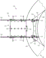
图1示出了本发明的停放组件100的实施例并且示出了被布置成接收工作平台的水平部分101、被成形为紧靠海上设施的直立元件的竖直部分102以及适于将停放组件100可拆卸地联接到海上设施的直立元件的联接布置。在该示例性实施例中,水平部分101被实现为大梁和支柱的框架。在此,水平部分101包括形式为两个对角的对中指状物110的对中布置110、111。此外,水平部分101包括四个竖直的对中指状物111。对中布置110、111有助于将工作平台布置在水平部分101上。橡胶挡板(fender)112确保工作平台的牢固竖立。为了将停放组件100在海上设施处提升就位,水平部分101的每侧包括用于提升设备(例如起重机)的线缆的两个附接点113。此外,水平部分101的每侧包括用于标记线或引导绳的三个附接点114,该标记线能够被用于在安装期间稳定停放组件100。在该示例性实施例中,水平部分101的每侧还包括三个附接点115,以允许工作平台被绑到停放组件100。Figure 1 shows an embodiment of the
在该示例性实施例中,停放组件100的水平部分101和竖直部分102被实现为L形。竖直部分102借助于两个内部腿部120在水平部分101和海上设施的下水平之间延伸。每个内部腿部120终止于脚板121中,该脚板121被布置成搁置在海上设施的下水平上,例如在风力涡轮机的过渡件上。In this exemplary embodiment, the
在该示例性实施例中,竖直部分102的框架是弯曲的,以匹配风力涡轮机塔架的外表面的曲率。此外,竖直部分102包括四个接触表面122,其被成形为紧靠塔架的外表面。接触表面122以竖直布置被提供在内部腿部120上并且能够匹配基本上任何风力涡轮机塔架的曲率。为了在安装期间调节停放组件100围绕塔架的位置,提供两个水平可调节的轮116。一旦停放组件100就位,则轮116能够缩回。当停放组件100不使用时,例如在船上时,两个另外的支撑腿部123为停放组件100提供安全且水平的竖立。In the exemplary embodiment, the frame of
停放组件100到塔架的可拆卸联接由联接布置实现。在该示例性实施例中,联接布置的固定点在竖直部分102上的两个不同位置处被连接到停放组件100。在该示例性实施例中,联接布置将包括弹性带130和受保护的钢丝绳131以水平地环绕塔架。在竖直部分102的一侧处,联接布置附加地包括绞盘132,其将被用于拉紧带。在该示例性实施例中,联接布置也包括被布置成面向直立元件的两个磁体133。为了在海上设施的下水平和搁置在水平部分101上的工作平台之间的接近,该示例性实施例的停放组件100包括中间平台105和多个梯子150。The detachable coupling of the
图2和图3分别示出了被附接到风力涡轮机106的塔架160的图1的停放组件100的竖直截面和俯视图。竖直部分102及其接触表面122被成形为紧靠塔架160的外表面。接触表面122基本上用作在竖直部分102和风力涡轮机106的塔架160之间的间隔件。水平部分101和竖直部分102联结成L形,同时水平部分101突出超过风力涡轮机106的过渡件161的栏杆162。以此方式,中间平台105延伸超过过渡件161的栏杆162且余隙由竖直部分102的高度确定。FIGS. 2 and 3 show vertical cross-section and top views, respectively, of the
在停放组件100的优选实施例中,在水平部分101和过渡件161之间的竖直距离是可调节的。依赖于过渡件栏杆162的高度和过渡件161的设计,内部腿部120的高度能够是可调节的,以在停放组件100被安装时维持在水平部分101和过渡件栏杆162之间的余隙。梯子150的调平脚部能够被调节成便于从过渡件161接近工作平台。在该示例性实施例中,联接布置103包括弹性带130和受保护的钢丝绳131,从而环绕塔架160。在竖直部分102的一侧处,联接布置103也包括绞盘132以有助于张紧带130。In the preferred embodiment of the
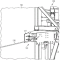
图4至图9示出了在停放组件100到塔架160的联接过程的不同阶段期间的联接布置103的细节。一旦停放组件100通过适合的提升设备放置在过渡件上,则竖直部分的脚部元件优选地搁置在过渡件平台(未示出)上,同时接触表面122如图4中所示地与塔架160的外表面进行接触。针对整个联接程序,停放组件100保持附接到提升设备。4 to 9 show details of the
在联接程序开始时,弹性带130使用钩环134而附接到联接布置103的特定固定点141而不使用绞盘(图4)。弹性带130环绕塔架160并且被连接到联接布置103,该联接布置103在竖直部分的相对侧处包括绞盘132(图5)。弹性带130被吊索136和钩环134连接到绞盘132的滑轮135。绞盘132的绳137通过钩环134附接到联接布置103。一旦弹性带130通过操作绞盘132而被张紧,则套筒螺母138使用钩环134而附接到联接布置103的适合的组装孔139。套筒螺母138在一端处使用特殊的螺栓140或固位销而固定到竖直部分102。弹性带130通过第二吊索136和钩环134连接到套筒螺母138的另一端。一旦弹性带130通过绞盘132和套筒螺母138牢固地拉紧,则绞盘132被分离,如图7中所示。弹性带130现在围绕塔架160就位并且保持支撑结构就位。At the beginning of the coupling procedure, the
图8示出了使用钩环134将受保护的钢丝绳131联接到联接布置103的特定固定点142的最初步骤。如上文所描述,弹性带130已经就位。受保护的钢丝绳131被布置成环绕塔架160并且通过吊索136和钩环134附接到另一套筒螺母138(图9)。套筒螺母138被附接到联接布置103的特定联接点142,这能够根据组装孔139被调节。一旦被受保护的钢丝绳131的套筒螺母138被拉紧,则停放组件100被完全固定。FIG. 8 shows the initial steps of using the
在本发明的一个实施例中,弹性带和受保护的钢丝绳能够以彼此交叉的方式被附接到联接布置。在竖直部分的每侧处,一个带通过钩环直接地附接到联接布置的固定点,同时另一个带被附接到套筒螺母。In one embodiment of the invention, the elastic band and the protected wire rope can be attached to the coupling arrangement in such a way that they cross each other. At each side of the vertical section, one strap is attached directly to the fixing point of the coupling arrangement by means of a shackle, while the other strap is attached to the turnbuckle.
在将停放组件固定到海上设施的直立元件之后,停放组件与提升设备分离并且准备好接收工作平台,该工作平台通过适合的提升设备(诸如起重机)降低到停放组件。After securing the docking assembly to the upright element of the offshore installation, the docking assembly is detached from the lifting equipment and is ready to receive a work platform, which is lowered to the docking assembly by suitable lifting equipment, such as a crane.
图10示出了被附接到风力涡轮机106的塔架160的本发明的停放组件100的优选实施例,其中工作平台107搁置在水平部分上。竖直部分102紧靠塔架160的壁并且利用两个腿部120搁置在过渡件161上。水平部分且同样地中间平台105突出超过过渡件栏杆162。停放组件100通过环绕塔架160的弹性带130和受保护的钢丝绳131而可拆卸地联接到塔架160。在使用时工作平台107能够通过起重机沿着塔架160向上提升,该起重机被安装在风力涡轮机106的机舱的水平上。当不使用时,工作平台107能够被绑到停放组件100。Figure 10 shows a preferred embodiment of the
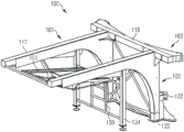
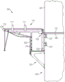
图11和图12示出了本发明的停放组件100的另一实施例。该实施例的特征在于更坚固的构造。水平部分101由两个平行的水平大梁117和一个横梁118实现。竖直部分102被成形为紧靠风力涡轮机的塔架(图11)。内部腿部120由托架和交叉支柱稳定。在该实施例中,停放组件100包括两个外部腿部124。通过梯子150和引导轨道151来实现从过渡件接近工作平台。停放组件100的竖直部分102和水平部分101能够包括附加包覆层。图12示出了被附接到风力涡轮机塔架160的停放组件100的该实施例的竖直截面。竖直部分的内部腿部120紧挨着塔架160而搁置在过渡件161上,同时外部腿部124位于正搁置在单桩163上的过渡件161的栏杆162附近。在此,腿部120、124在高度及其水平位置方面是可调节的以匹配过渡件161和过渡件栏杆162的不同设计。11 and 12 illustrate another embodiment of the
虽然已经以优选实施例及其变型的形式描述了本发明,不过将理解的是,在不背离本发明范围的情况下能够对其作出许多附加的修改和变型。为了清楚起见,应该理解,贯穿本申请使用“一”或“一个”不排除多个,并且“包括”不排除其它步骤或者要素。While the present invention has been described in terms of the preferred embodiments and variations thereof, it will be understood that many additional modifications and variations can be made thereto without departing from the scope of the invention. For clarity, it should be understood that the use of "a" or "an" throughout this application does not exclude a plurality and "comprising" does not exclude other steps or elements.
Claims (11)
Applications Claiming Priority (3)
| Application Number | Priority Date | Filing Date | Title |
|---|---|---|---|
| DE102017205807.2 | 2017-04-05 | ||
| DE102017205807 | 2017-04-05 | ||
| PCT/EP2018/050416 WO2018184741A1 (en) | 2017-04-05 | 2018-01-09 | Parking assembly |
Publications (2)
| Publication Number | Publication Date |
|---|---|
| CN110691908A CN110691908A (en) | 2020-01-14 |
| CN110691908B true CN110691908B (en) | 2022-04-12 |
Family
ID=61094408
Family Applications (1)
| Application Number | Title | Priority Date | Filing Date |
|---|---|---|---|
| CN201880037452.3A Active CN110691908B (en) | 2017-04-05 | 2018-01-09 | parked components |
Country Status (4)
| Country | Link |
|---|---|
| EP (1) | EP3586001B1 (en) |
| CN (1) | CN110691908B (en) |
| DK (1) | DK3586001T3 (en) |
| WO (1) | WO2018184741A1 (en) |
Families Citing this family (1)
| Publication number | Priority date | Publication date | Assignee | Title |
|---|---|---|---|---|
| CN113883018B (en) * | 2021-09-28 | 2022-06-10 | 江苏久力风电技术开发有限公司 | Aerogenerator pylon with automatic rising function |
Citations (9)
| Publication number | Priority date | Publication date | Assignee | Title |
|---|---|---|---|---|
| CN1902398A (en) * | 2003-12-30 | 2007-01-24 | Pp能源有限责任公司 | Device for enabling access to a structure above ground level |
| EP1878652A2 (en) * | 2006-07-13 | 2008-01-16 | Jan They | Buoyancy supported offshore foundation for wind power stations and other constructions |
| KR100928570B1 (en) * | 2009-07-30 | 2009-11-24 | 주식회사 항도엔지니어링 | Offshore wind power generator with seaweed and fish reef functions |
| CN101993020A (en) * | 2009-08-04 | 2011-03-30 | 通用电气公司 | Tower climbing and servicing device |
| CN103225589A (en) * | 2012-01-30 | 2013-07-31 | 西门子公司 | Improvements to a wind turbine assembly |
| CN103477005A (en) * | 2011-03-04 | 2013-12-25 | 因内奥托雷斯有限公司 | Method for accessing the outer surface of wind turbine towers and device for use with this method |
| KR20140085695A (en) * | 2012-12-27 | 2014-07-08 | 전자부품연구원 | Maintenance workbench of wind power generator and workbench structure thereof |
| EP2809946A2 (en) * | 2012-01-31 | 2014-12-10 | Fachhochschule Aachen | Climbing robot for masts |
| CN104755751A (en) * | 2012-10-22 | 2015-07-01 | 乌本产权有限公司 | Wind power plant and wind power plant tower |
Family Cites Families (2)
| Publication number | Priority date | Publication date | Assignee | Title |
|---|---|---|---|---|
| DK1706636T3 (en) * | 2003-12-30 | 2018-11-05 | Pp Energy Aps | Device to enable access to a ground level construction |
| DE102010009916A1 (en) * | 2010-03-02 | 2011-09-08 | Daniel Reinsberg | Device for supply and service on towers, particularly for offshore wind turbines, has container, which is fastened to tower in temporary manner, where clamping unit for clasping and clamping tower shaft is arranged at base frame |
-
2018
- 2018-01-09 WO PCT/EP2018/050416 patent/WO2018184741A1/en unknown
- 2018-01-09 CN CN201880037452.3A patent/CN110691908B/en active Active
- 2018-01-09 EP EP18702082.1A patent/EP3586001B1/en active Active
- 2018-01-09 DK DK18702082.1T patent/DK3586001T3/en active
Patent Citations (9)
| Publication number | Priority date | Publication date | Assignee | Title |
|---|---|---|---|---|
| CN1902398A (en) * | 2003-12-30 | 2007-01-24 | Pp能源有限责任公司 | Device for enabling access to a structure above ground level |
| EP1878652A2 (en) * | 2006-07-13 | 2008-01-16 | Jan They | Buoyancy supported offshore foundation for wind power stations and other constructions |
| KR100928570B1 (en) * | 2009-07-30 | 2009-11-24 | 주식회사 항도엔지니어링 | Offshore wind power generator with seaweed and fish reef functions |
| CN101993020A (en) * | 2009-08-04 | 2011-03-30 | 通用电气公司 | Tower climbing and servicing device |
| CN103477005A (en) * | 2011-03-04 | 2013-12-25 | 因内奥托雷斯有限公司 | Method for accessing the outer surface of wind turbine towers and device for use with this method |
| CN103225589A (en) * | 2012-01-30 | 2013-07-31 | 西门子公司 | Improvements to a wind turbine assembly |
| EP2809946A2 (en) * | 2012-01-31 | 2014-12-10 | Fachhochschule Aachen | Climbing robot for masts |
| CN104755751A (en) * | 2012-10-22 | 2015-07-01 | 乌本产权有限公司 | Wind power plant and wind power plant tower |
| KR20140085695A (en) * | 2012-12-27 | 2014-07-08 | 전자부품연구원 | Maintenance workbench of wind power generator and workbench structure thereof |
Also Published As
| Publication number | Publication date |
|---|---|
| EP3586001B1 (en) | 2021-02-24 |
| EP3586001A1 (en) | 2020-01-01 |
| WO2018184741A1 (en) | 2018-10-11 |
| CN110691908A (en) | 2020-01-14 |
| DK3586001T3 (en) | 2021-04-26 |
Similar Documents
| Publication | Publication Date | Title |
|---|---|---|
| US10125507B2 (en) | Fall protection system | |
| EP3032097B1 (en) | Wind turbine tower with an elevator system | |
| US10934994B2 (en) | Method and system for de-erection and re-erection of a blade of a wind turbine | |
| US11629698B2 (en) | Device for mounting wind turbine components and mounting method using said device | |
| US20100126801A1 (en) | Fall arrest apparatus | |
| US20170067447A1 (en) | Wind Turbine Blade Removal and Installation System and Method | |
| US20090020363A1 (en) | Scaffolding fall protection system | |
| CN104695752B (en) | Rapid rush-repair Tower System and its erection method | |
| US20210270241A1 (en) | System for Craneless Blade Mounting and Dismounting at Wind Turbines | |
| CN110691908B (en) | parked components | |
| JP7325838B2 (en) | Movable modules for lifting telescopic towers and methods for lifting telescopic towers | |
| CN109138821B (en) | A portable insulating ladder platform that can be assembled | |
| JP5589183B2 (en) | Cylindrical structure scaffolding apparatus and moving method thereof | |
| US9869294B2 (en) | Safety structure for performing servicing operations in a wind turbine and method for its installation | |
| RU167382U1 (en) | DESIGN FOR FASTENING PROTECTIVE WORKERS ON LONG-DIMENSIONAL HEIGHT SUPPORTS | |
| CN110284700B (en) | Operating platform applied to hyperboloid space structure and construction method | |
| JP2023552909A (en) | How to assemble a floating offshore wind farm | |
| US9630033B2 (en) | Temporary fall protection | |
| JP2008086709A (en) | Downfall prevention device and method of installing carrier cable for preventing downfall | |
| CN103848359B (en) | A kind of soft attaching structure of tower crane | |
| CN219605468U (en) | Concrete tower section of thick bamboo protection network platform structure | |
| JP2012233344A (en) | Method for connecting mast, and device for use in the same | |
| CN107973238A (en) | Cable restocking service hoisting frock and cable pavement system | |
| ES2543647B1 (en) | ARRIOSTRATED TOWER ASSEMBLY DEVICE AND ARRIOSTRATED TOWER ASSEMBLY PROCEDURE | |
| WO2024227226A1 (en) | Safety system |
Legal Events
| Date | Code | Title | Description |
|---|---|---|---|
| PB01 | Publication | ||
| PB01 | Publication | ||
| SE01 | Entry into force of request for substantive examination | ||
| SE01 | Entry into force of request for substantive examination | ||
| GR01 | Patent grant | ||
| GR01 | Patent grant |