CN110678406B - Devices and methods relating to medical tubes - Google Patents
Devices and methods relating to medical tubes Download PDFInfo
- Publication number
- CN110678406B CN110678406B CN201880018193.XA CN201880018193A CN110678406B CN 110678406 B CN110678406 B CN 110678406B CN 201880018193 A CN201880018193 A CN 201880018193A CN 110678406 B CN110678406 B CN 110678406B
- Authority
- CN
- China
- Prior art keywords
- spool
- drive system
- medical tube
- tube
- guidewire
- Prior art date
- Legal status (The legal status is an assumption and is not a legal conclusion. Google has not performed a legal analysis and makes no representation as to the accuracy of the status listed.)
- Active
Links
Images


Classifications
-
- A—HUMAN NECESSITIES
- A61—MEDICAL OR VETERINARY SCIENCE; HYGIENE
- A61B—DIAGNOSIS; SURGERY; IDENTIFICATION
- A61B90/00—Instruments, implements or accessories specially adapted for surgery or diagnosis and not covered by any of the groups A61B1/00 - A61B50/00, e.g. for luxation treatment or for protecting wound edges
- A61B90/70—Cleaning devices specially adapted for surgical instruments
-
- B—PERFORMING OPERATIONS; TRANSPORTING
- B65—CONVEYING; PACKING; STORING; HANDLING THIN OR FILAMENTARY MATERIAL
- B65H—HANDLING THIN OR FILAMENTARY MATERIAL, e.g. SHEETS, WEBS, CABLES
- B65H75/00—Storing webs, tapes, or filamentary material, e.g. on reels
- B65H75/02—Cores, formers, supports, or holders for coiled, wound, or folded material, e.g. reels, spindles, bobbins, cop tubes, cans, mandrels or chucks
- B65H75/34—Cores, formers, supports, or holders for coiled, wound, or folded material, e.g. reels, spindles, bobbins, cop tubes, cans, mandrels or chucks specially adapted or mounted for storing and repeatedly paying-out and re-storing lengths of material provided for particular purposes, e.g. anchored hoses, power cables
- B65H75/36—Cores, formers, supports, or holders for coiled, wound, or folded material, e.g. reels, spindles, bobbins, cop tubes, cans, mandrels or chucks specially adapted or mounted for storing and repeatedly paying-out and re-storing lengths of material provided for particular purposes, e.g. anchored hoses, power cables without essentially involving the use of a core or former internal to a stored package of material, e.g. with stored material housed within casing or container, or intermittently engaging a plurality of supports as in sinuous or serpentine fashion
- B65H75/362—Cores, formers, supports, or holders for coiled, wound, or folded material, e.g. reels, spindles, bobbins, cop tubes, cans, mandrels or chucks specially adapted or mounted for storing and repeatedly paying-out and re-storing lengths of material provided for particular purposes, e.g. anchored hoses, power cables without essentially involving the use of a core or former internal to a stored package of material, e.g. with stored material housed within casing or container, or intermittently engaging a plurality of supports as in sinuous or serpentine fashion with stored material housed within a casing or container
- B65H75/364—Cores, formers, supports, or holders for coiled, wound, or folded material, e.g. reels, spindles, bobbins, cop tubes, cans, mandrels or chucks specially adapted or mounted for storing and repeatedly paying-out and re-storing lengths of material provided for particular purposes, e.g. anchored hoses, power cables without essentially involving the use of a core or former internal to a stored package of material, e.g. with stored material housed within casing or container, or intermittently engaging a plurality of supports as in sinuous or serpentine fashion with stored material housed within a casing or container the stored material being coiled
-
- A—HUMAN NECESSITIES
- A61—MEDICAL OR VETERINARY SCIENCE; HYGIENE
- A61B—DIAGNOSIS; SURGERY; IDENTIFICATION
- A61B5/00—Measuring for diagnostic purposes; Identification of persons
- A61B5/0002—Remote monitoring of patients using telemetry, e.g. transmission of vital signals via a communication network
- A61B5/0015—Remote monitoring of patients using telemetry, e.g. transmission of vital signals via a communication network characterised by features of the telemetry system
- A61B5/0022—Monitoring a patient using a global network, e.g. telephone networks, internet
-
- A—HUMAN NECESSITIES
- A61—MEDICAL OR VETERINARY SCIENCE; HYGIENE
- A61B—DIAGNOSIS; SURGERY; IDENTIFICATION
- A61B5/00—Measuring for diagnostic purposes; Identification of persons
- A61B5/01—Measuring temperature of body parts ; Diagnostic temperature sensing, e.g. for malignant or inflamed tissue
-
- A—HUMAN NECESSITIES
- A61—MEDICAL OR VETERINARY SCIENCE; HYGIENE
- A61B—DIAGNOSIS; SURGERY; IDENTIFICATION
- A61B5/00—Measuring for diagnostic purposes; Identification of persons
- A61B5/02—Detecting, measuring or recording pulse, heart rate, blood pressure or blood flow; Combined pulse/heart-rate/blood pressure determination; Evaluating a cardiovascular condition not otherwise provided for, e.g. using combinations of techniques provided for in this group with electrocardiography or electroauscultation; Heart catheters for measuring blood pressure
- A61B5/0205—Simultaneously evaluating both cardiovascular conditions and different types of body conditions, e.g. heart and respiratory condition
- A61B5/02055—Simultaneously evaluating both cardiovascular condition and temperature
-
- A—HUMAN NECESSITIES
- A61—MEDICAL OR VETERINARY SCIENCE; HYGIENE
- A61B—DIAGNOSIS; SURGERY; IDENTIFICATION
- A61B5/00—Measuring for diagnostic purposes; Identification of persons
- A61B5/02—Detecting, measuring or recording pulse, heart rate, blood pressure or blood flow; Combined pulse/heart-rate/blood pressure determination; Evaluating a cardiovascular condition not otherwise provided for, e.g. using combinations of techniques provided for in this group with electrocardiography or electroauscultation; Heart catheters for measuring blood pressure
- A61B5/024—Detecting, measuring or recording pulse rate or heart rate
-
- A—HUMAN NECESSITIES
- A61—MEDICAL OR VETERINARY SCIENCE; HYGIENE
- A61B—DIAGNOSIS; SURGERY; IDENTIFICATION
- A61B5/00—Measuring for diagnostic purposes; Identification of persons
- A61B5/08—Detecting, measuring or recording devices for evaluating the respiratory organs
- A61B5/0816—Measuring devices for examining respiratory frequency
-
- A—HUMAN NECESSITIES
- A61—MEDICAL OR VETERINARY SCIENCE; HYGIENE
- A61B—DIAGNOSIS; SURGERY; IDENTIFICATION
- A61B5/00—Measuring for diagnostic purposes; Identification of persons
- A61B5/08—Detecting, measuring or recording devices for evaluating the respiratory organs
- A61B5/0823—Detecting or evaluating cough events
-
- A—HUMAN NECESSITIES
- A61—MEDICAL OR VETERINARY SCIENCE; HYGIENE
- A61B—DIAGNOSIS; SURGERY; IDENTIFICATION
- A61B5/00—Measuring for diagnostic purposes; Identification of persons
- A61B5/103—Detecting, measuring or recording devices for testing the shape, pattern, colour, size or movement of the body or parts thereof, for diagnostic purposes
- A61B5/11—Measuring movement of the entire body or parts thereof, e.g. head or hand tremor, mobility of a limb
- A61B5/1113—Local tracking of patients, e.g. in a hospital or private home
-
- A—HUMAN NECESSITIES
- A61—MEDICAL OR VETERINARY SCIENCE; HYGIENE
- A61B—DIAGNOSIS; SURGERY; IDENTIFICATION
- A61B5/00—Measuring for diagnostic purposes; Identification of persons
- A61B5/103—Detecting, measuring or recording devices for testing the shape, pattern, colour, size or movement of the body or parts thereof, for diagnostic purposes
- A61B5/11—Measuring movement of the entire body or parts thereof, e.g. head or hand tremor, mobility of a limb
- A61B5/1118—Determining activity level
-
- A—HUMAN NECESSITIES
- A61—MEDICAL OR VETERINARY SCIENCE; HYGIENE
- A61B—DIAGNOSIS; SURGERY; IDENTIFICATION
- A61B5/00—Measuring for diagnostic purposes; Identification of persons
- A61B5/24—Detecting, measuring or recording bioelectric or biomagnetic signals of the body or parts thereof
- A61B5/316—Modalities, i.e. specific diagnostic methods
- A61B5/318—Heart-related electrical modalities, e.g. electrocardiography [ECG]
- A61B5/346—Analysis of electrocardiograms
- A61B5/349—Detecting specific parameters of the electrocardiograph cycle
-
- A—HUMAN NECESSITIES
- A61—MEDICAL OR VETERINARY SCIENCE; HYGIENE
- A61B—DIAGNOSIS; SURGERY; IDENTIFICATION
- A61B5/00—Measuring for diagnostic purposes; Identification of persons
- A61B5/48—Other medical applications
- A61B5/4824—Touch or pain perception evaluation
-
- A—HUMAN NECESSITIES
- A61—MEDICAL OR VETERINARY SCIENCE; HYGIENE
- A61M—DEVICES FOR INTRODUCING MEDIA INTO, OR ONTO, THE BODY; DEVICES FOR TRANSDUCING BODY MEDIA OR FOR TAKING MEDIA FROM THE BODY; DEVICES FOR PRODUCING OR ENDING SLEEP OR STUPOR
- A61M1/00—Suction or pumping devices for medical purposes; Devices for carrying-off, for treatment of, or for carrying-over, body-liquids; Drainage systems
- A61M1/71—Suction drainage systems
- A61M1/74—Suction control
- A61M1/75—Intermittent or pulsating suction
-
- A—HUMAN NECESSITIES
- A61—MEDICAL OR VETERINARY SCIENCE; HYGIENE
- A61M—DEVICES FOR INTRODUCING MEDIA INTO, OR ONTO, THE BODY; DEVICES FOR TRANSDUCING BODY MEDIA OR FOR TAKING MEDIA FROM THE BODY; DEVICES FOR PRODUCING OR ENDING SLEEP OR STUPOR
- A61M1/00—Suction or pumping devices for medical purposes; Devices for carrying-off, for treatment of, or for carrying-over, body-liquids; Drainage systems
- A61M1/83—Tube strippers, i.e. for clearing the contents of the tubes
-
- A—HUMAN NECESSITIES
- A61—MEDICAL OR VETERINARY SCIENCE; HYGIENE
- A61M—DEVICES FOR INTRODUCING MEDIA INTO, OR ONTO, THE BODY; DEVICES FOR TRANSDUCING BODY MEDIA OR FOR TAKING MEDIA FROM THE BODY; DEVICES FOR PRODUCING OR ENDING SLEEP OR STUPOR
- A61M1/00—Suction or pumping devices for medical purposes; Devices for carrying-off, for treatment of, or for carrying-over, body-liquids; Drainage systems
- A61M1/84—Drainage tubes; Aspiration tips
- A61M1/86—Connectors between drainage tube and handpiece, e.g. drainage tubes detachable from handpiece
-
- A—HUMAN NECESSITIES
- A61—MEDICAL OR VETERINARY SCIENCE; HYGIENE
- A61M—DEVICES FOR INTRODUCING MEDIA INTO, OR ONTO, THE BODY; DEVICES FOR TRANSDUCING BODY MEDIA OR FOR TAKING MEDIA FROM THE BODY; DEVICES FOR PRODUCING OR ENDING SLEEP OR STUPOR
- A61M25/00—Catheters; Hollow probes
- A61M25/01—Introducing, guiding, advancing, emplacing or holding catheters
- A61M25/0105—Steering means as part of the catheter or advancing means; Markers for positioning
- A61M25/0111—Aseptic insertion devices
-
- A—HUMAN NECESSITIES
- A61—MEDICAL OR VETERINARY SCIENCE; HYGIENE
- A61M—DEVICES FOR INTRODUCING MEDIA INTO, OR ONTO, THE BODY; DEVICES FOR TRANSDUCING BODY MEDIA OR FOR TAKING MEDIA FROM THE BODY; DEVICES FOR PRODUCING OR ENDING SLEEP OR STUPOR
- A61M25/00—Catheters; Hollow probes
- A61M25/01—Introducing, guiding, advancing, emplacing or holding catheters
- A61M25/0105—Steering means as part of the catheter or advancing means; Markers for positioning
- A61M25/0113—Mechanical advancing means, e.g. catheter dispensers
-
- A—HUMAN NECESSITIES
- A61—MEDICAL OR VETERINARY SCIENCE; HYGIENE
- A61M—DEVICES FOR INTRODUCING MEDIA INTO, OR ONTO, THE BODY; DEVICES FOR TRANSDUCING BODY MEDIA OR FOR TAKING MEDIA FROM THE BODY; DEVICES FOR PRODUCING OR ENDING SLEEP OR STUPOR
- A61M25/00—Catheters; Hollow probes
- A61M25/01—Introducing, guiding, advancing, emplacing or holding catheters
- A61M25/0172—Exchanging a guidewire while keeping the catheter in place
-
- A—HUMAN NECESSITIES
- A61—MEDICAL OR VETERINARY SCIENCE; HYGIENE
- A61M—DEVICES FOR INTRODUCING MEDIA INTO, OR ONTO, THE BODY; DEVICES FOR TRANSDUCING BODY MEDIA OR FOR TAKING MEDIA FROM THE BODY; DEVICES FOR PRODUCING OR ENDING SLEEP OR STUPOR
- A61M25/00—Catheters; Hollow probes
- A61M25/10—Balloon catheters
- A61M25/1018—Balloon inflating or inflation-control devices
-
- A—HUMAN NECESSITIES
- A61—MEDICAL OR VETERINARY SCIENCE; HYGIENE
- A61M—DEVICES FOR INTRODUCING MEDIA INTO, OR ONTO, THE BODY; DEVICES FOR TRANSDUCING BODY MEDIA OR FOR TAKING MEDIA FROM THE BODY; DEVICES FOR PRODUCING OR ENDING SLEEP OR STUPOR
- A61M27/00—Drainage appliance for wounds or the like, i.e. wound drains, implanted drains
-
- B—PERFORMING OPERATIONS; TRANSPORTING
- B08—CLEANING
- B08B—CLEANING IN GENERAL; PREVENTION OF FOULING IN GENERAL
- B08B9/00—Cleaning hollow articles by methods or apparatus specially adapted thereto
- B08B9/02—Cleaning pipes or tubes or systems of pipes or tubes
-
- B—PERFORMING OPERATIONS; TRANSPORTING
- B65—CONVEYING; PACKING; STORING; HANDLING THIN OR FILAMENTARY MATERIAL
- B65H—HANDLING THIN OR FILAMENTARY MATERIAL, e.g. SHEETS, WEBS, CABLES
- B65H75/00—Storing webs, tapes, or filamentary material, e.g. on reels
- B65H75/02—Cores, formers, supports, or holders for coiled, wound, or folded material, e.g. reels, spindles, bobbins, cop tubes, cans, mandrels or chucks
- B65H75/34—Cores, formers, supports, or holders for coiled, wound, or folded material, e.g. reels, spindles, bobbins, cop tubes, cans, mandrels or chucks specially adapted or mounted for storing and repeatedly paying-out and re-storing lengths of material provided for particular purposes, e.g. anchored hoses, power cables
- B65H75/38—Cores, formers, supports, or holders for coiled, wound, or folded material, e.g. reels, spindles, bobbins, cop tubes, cans, mandrels or chucks specially adapted or mounted for storing and repeatedly paying-out and re-storing lengths of material provided for particular purposes, e.g. anchored hoses, power cables involving the use of a core or former internal to, and supporting, a stored package of material
- B65H75/40—Cores, formers, supports, or holders for coiled, wound, or folded material, e.g. reels, spindles, bobbins, cop tubes, cans, mandrels or chucks specially adapted or mounted for storing and repeatedly paying-out and re-storing lengths of material provided for particular purposes, e.g. anchored hoses, power cables involving the use of a core or former internal to, and supporting, a stored package of material mobile or transportable
- B65H75/406—Cores, formers, supports, or holders for coiled, wound, or folded material, e.g. reels, spindles, bobbins, cop tubes, cans, mandrels or chucks specially adapted or mounted for storing and repeatedly paying-out and re-storing lengths of material provided for particular purposes, e.g. anchored hoses, power cables involving the use of a core or former internal to, and supporting, a stored package of material mobile or transportable hand-held during use
-
- B—PERFORMING OPERATIONS; TRANSPORTING
- B65—CONVEYING; PACKING; STORING; HANDLING THIN OR FILAMENTARY MATERIAL
- B65H—HANDLING THIN OR FILAMENTARY MATERIAL, e.g. SHEETS, WEBS, CABLES
- B65H75/00—Storing webs, tapes, or filamentary material, e.g. on reels
- B65H75/02—Cores, formers, supports, or holders for coiled, wound, or folded material, e.g. reels, spindles, bobbins, cop tubes, cans, mandrels or chucks
- B65H75/34—Cores, formers, supports, or holders for coiled, wound, or folded material, e.g. reels, spindles, bobbins, cop tubes, cans, mandrels or chucks specially adapted or mounted for storing and repeatedly paying-out and re-storing lengths of material provided for particular purposes, e.g. anchored hoses, power cables
- B65H75/38—Cores, formers, supports, or holders for coiled, wound, or folded material, e.g. reels, spindles, bobbins, cop tubes, cans, mandrels or chucks specially adapted or mounted for storing and repeatedly paying-out and re-storing lengths of material provided for particular purposes, e.g. anchored hoses, power cables involving the use of a core or former internal to, and supporting, a stored package of material
- B65H75/44—Constructional details
- B65H75/4402—Guiding arrangements to control paying-out and re-storing of the material
-
- B—PERFORMING OPERATIONS; TRANSPORTING
- B65—CONVEYING; PACKING; STORING; HANDLING THIN OR FILAMENTARY MATERIAL
- B65H—HANDLING THIN OR FILAMENTARY MATERIAL, e.g. SHEETS, WEBS, CABLES
- B65H75/00—Storing webs, tapes, or filamentary material, e.g. on reels
- B65H75/02—Cores, formers, supports, or holders for coiled, wound, or folded material, e.g. reels, spindles, bobbins, cop tubes, cans, mandrels or chucks
- B65H75/34—Cores, formers, supports, or holders for coiled, wound, or folded material, e.g. reels, spindles, bobbins, cop tubes, cans, mandrels or chucks specially adapted or mounted for storing and repeatedly paying-out and re-storing lengths of material provided for particular purposes, e.g. anchored hoses, power cables
- B65H75/38—Cores, formers, supports, or holders for coiled, wound, or folded material, e.g. reels, spindles, bobbins, cop tubes, cans, mandrels or chucks specially adapted or mounted for storing and repeatedly paying-out and re-storing lengths of material provided for particular purposes, e.g. anchored hoses, power cables involving the use of a core or former internal to, and supporting, a stored package of material
- B65H75/44—Constructional details
- B65H75/4457—Arrangements of the frame or housing
- B65H75/4471—Housing enclosing the reel
-
- B—PERFORMING OPERATIONS; TRANSPORTING
- B65—CONVEYING; PACKING; STORING; HANDLING THIN OR FILAMENTARY MATERIAL
- B65H—HANDLING THIN OR FILAMENTARY MATERIAL, e.g. SHEETS, WEBS, CABLES
- B65H75/00—Storing webs, tapes, or filamentary material, e.g. on reels
- B65H75/02—Cores, formers, supports, or holders for coiled, wound, or folded material, e.g. reels, spindles, bobbins, cop tubes, cans, mandrels or chucks
- B65H75/34—Cores, formers, supports, or holders for coiled, wound, or folded material, e.g. reels, spindles, bobbins, cop tubes, cans, mandrels or chucks specially adapted or mounted for storing and repeatedly paying-out and re-storing lengths of material provided for particular purposes, e.g. anchored hoses, power cables
- B65H75/38—Cores, formers, supports, or holders for coiled, wound, or folded material, e.g. reels, spindles, bobbins, cop tubes, cans, mandrels or chucks specially adapted or mounted for storing and repeatedly paying-out and re-storing lengths of material provided for particular purposes, e.g. anchored hoses, power cables involving the use of a core or former internal to, and supporting, a stored package of material
- B65H75/44—Constructional details
- B65H75/4481—Arrangements or adaptations for driving the reel or the material
- B65H75/4486—Electric motors
-
- A—HUMAN NECESSITIES
- A61—MEDICAL OR VETERINARY SCIENCE; HYGIENE
- A61B—DIAGNOSIS; SURGERY; IDENTIFICATION
- A61B90/00—Instruments, implements or accessories specially adapted for surgery or diagnosis and not covered by any of the groups A61B1/00 - A61B50/00, e.g. for luxation treatment or for protecting wound edges
- A61B90/70—Cleaning devices specially adapted for surgical instruments
- A61B2090/701—Cleaning devices specially adapted for surgical instruments for flexible tubular instruments, e.g. endoscopes
-
- A—HUMAN NECESSITIES
- A61—MEDICAL OR VETERINARY SCIENCE; HYGIENE
- A61M—DEVICES FOR INTRODUCING MEDIA INTO, OR ONTO, THE BODY; DEVICES FOR TRANSDUCING BODY MEDIA OR FOR TAKING MEDIA FROM THE BODY; DEVICES FOR PRODUCING OR ENDING SLEEP OR STUPOR
- A61M25/00—Catheters; Hollow probes
- A61M2025/0019—Cleaning catheters or the like, e.g. for reuse of the device, for avoiding replacement
-
- A—HUMAN NECESSITIES
- A61—MEDICAL OR VETERINARY SCIENCE; HYGIENE
- A61M—DEVICES FOR INTRODUCING MEDIA INTO, OR ONTO, THE BODY; DEVICES FOR TRANSDUCING BODY MEDIA OR FOR TAKING MEDIA FROM THE BODY; DEVICES FOR PRODUCING OR ENDING SLEEP OR STUPOR
- A61M25/00—Catheters; Hollow probes
- A61M25/01—Introducing, guiding, advancing, emplacing or holding catheters
- A61M25/09—Guide wires
- A61M2025/09175—Guide wires having specific characteristics at the distal tip
- A61M2025/09183—Guide wires having specific characteristics at the distal tip having tools at the distal tip
-
- A—HUMAN NECESSITIES
- A61—MEDICAL OR VETERINARY SCIENCE; HYGIENE
- A61M—DEVICES FOR INTRODUCING MEDIA INTO, OR ONTO, THE BODY; DEVICES FOR TRANSDUCING BODY MEDIA OR FOR TAKING MEDIA FROM THE BODY; DEVICES FOR PRODUCING OR ENDING SLEEP OR STUPOR
- A61M2205/00—General characteristics of the apparatus
- A61M2205/02—General characteristics of the apparatus characterised by a particular materials
- A61M2205/0216—Materials providing elastic properties, e.g. for facilitating deformation and avoid breaking
-
- A—HUMAN NECESSITIES
- A61—MEDICAL OR VETERINARY SCIENCE; HYGIENE
- A61M—DEVICES FOR INTRODUCING MEDIA INTO, OR ONTO, THE BODY; DEVICES FOR TRANSDUCING BODY MEDIA OR FOR TAKING MEDIA FROM THE BODY; DEVICES FOR PRODUCING OR ENDING SLEEP OR STUPOR
- A61M2205/00—General characteristics of the apparatus
- A61M2205/18—General characteristics of the apparatus with alarm
-
- A—HUMAN NECESSITIES
- A61—MEDICAL OR VETERINARY SCIENCE; HYGIENE
- A61M—DEVICES FOR INTRODUCING MEDIA INTO, OR ONTO, THE BODY; DEVICES FOR TRANSDUCING BODY MEDIA OR FOR TAKING MEDIA FROM THE BODY; DEVICES FOR PRODUCING OR ENDING SLEEP OR STUPOR
- A61M2205/00—General characteristics of the apparatus
- A61M2205/33—Controlling, regulating or measuring
- A61M2205/3303—Using a biosensor
-
- A—HUMAN NECESSITIES
- A61—MEDICAL OR VETERINARY SCIENCE; HYGIENE
- A61M—DEVICES FOR INTRODUCING MEDIA INTO, OR ONTO, THE BODY; DEVICES FOR TRANSDUCING BODY MEDIA OR FOR TAKING MEDIA FROM THE BODY; DEVICES FOR PRODUCING OR ENDING SLEEP OR STUPOR
- A61M2205/00—General characteristics of the apparatus
- A61M2205/33—Controlling, regulating or measuring
- A61M2205/3324—PH measuring means
-
- A—HUMAN NECESSITIES
- A61—MEDICAL OR VETERINARY SCIENCE; HYGIENE
- A61M—DEVICES FOR INTRODUCING MEDIA INTO, OR ONTO, THE BODY; DEVICES FOR TRANSDUCING BODY MEDIA OR FOR TAKING MEDIA FROM THE BODY; DEVICES FOR PRODUCING OR ENDING SLEEP OR STUPOR
- A61M2205/00—General characteristics of the apparatus
- A61M2205/33—Controlling, regulating or measuring
- A61M2205/3331—Pressure; Flow
- A61M2205/3344—Measuring or controlling pressure at the body treatment site
-
- A—HUMAN NECESSITIES
- A61—MEDICAL OR VETERINARY SCIENCE; HYGIENE
- A61M—DEVICES FOR INTRODUCING MEDIA INTO, OR ONTO, THE BODY; DEVICES FOR TRANSDUCING BODY MEDIA OR FOR TAKING MEDIA FROM THE BODY; DEVICES FOR PRODUCING OR ENDING SLEEP OR STUPOR
- A61M2205/00—General characteristics of the apparatus
- A61M2205/50—General characteristics of the apparatus with microprocessors or computers
-
- A—HUMAN NECESSITIES
- A61—MEDICAL OR VETERINARY SCIENCE; HYGIENE
- A61M—DEVICES FOR INTRODUCING MEDIA INTO, OR ONTO, THE BODY; DEVICES FOR TRANSDUCING BODY MEDIA OR FOR TAKING MEDIA FROM THE BODY; DEVICES FOR PRODUCING OR ENDING SLEEP OR STUPOR
- A61M2205/00—General characteristics of the apparatus
- A61M2205/82—Internal energy supply devices
- A61M2205/8206—Internal energy supply devices battery-operated
-
- A—HUMAN NECESSITIES
- A61—MEDICAL OR VETERINARY SCIENCE; HYGIENE
- A61M—DEVICES FOR INTRODUCING MEDIA INTO, OR ONTO, THE BODY; DEVICES FOR TRANSDUCING BODY MEDIA OR FOR TAKING MEDIA FROM THE BODY; DEVICES FOR PRODUCING OR ENDING SLEEP OR STUPOR
- A61M2209/00—Ancillary equipment
- A61M2209/10—Equipment for cleaning
-
- A—HUMAN NECESSITIES
- A61—MEDICAL OR VETERINARY SCIENCE; HYGIENE
- A61M—DEVICES FOR INTRODUCING MEDIA INTO, OR ONTO, THE BODY; DEVICES FOR TRANSDUCING BODY MEDIA OR FOR TAKING MEDIA FROM THE BODY; DEVICES FOR PRODUCING OR ENDING SLEEP OR STUPOR
- A61M2210/00—Anatomical parts of the body
- A61M2210/10—Trunk
- A61M2210/101—Pleural cavity
-
- A—HUMAN NECESSITIES
- A61—MEDICAL OR VETERINARY SCIENCE; HYGIENE
- A61M—DEVICES FOR INTRODUCING MEDIA INTO, OR ONTO, THE BODY; DEVICES FOR TRANSDUCING BODY MEDIA OR FOR TAKING MEDIA FROM THE BODY; DEVICES FOR PRODUCING OR ENDING SLEEP OR STUPOR
- A61M2230/00—Measuring parameters of the user
- A61M2230/20—Blood composition characteristics
- A61M2230/201—Glucose concentration
-
- A—HUMAN NECESSITIES
- A61—MEDICAL OR VETERINARY SCIENCE; HYGIENE
- A61M—DEVICES FOR INTRODUCING MEDIA INTO, OR ONTO, THE BODY; DEVICES FOR TRANSDUCING BODY MEDIA OR FOR TAKING MEDIA FROM THE BODY; DEVICES FOR PRODUCING OR ENDING SLEEP OR STUPOR
- A61M2230/00—Measuring parameters of the user
- A61M2230/20—Blood composition characteristics
- A61M2230/207—Blood composition characteristics hematocrit
-
- A—HUMAN NECESSITIES
- A61—MEDICAL OR VETERINARY SCIENCE; HYGIENE
- A61M—DEVICES FOR INTRODUCING MEDIA INTO, OR ONTO, THE BODY; DEVICES FOR TRANSDUCING BODY MEDIA OR FOR TAKING MEDIA FROM THE BODY; DEVICES FOR PRODUCING OR ENDING SLEEP OR STUPOR
- A61M2230/00—Measuring parameters of the user
- A61M2230/20—Blood composition characteristics
- A61M2230/208—Blood composition characteristics pH-value
-
- A—HUMAN NECESSITIES
- A61—MEDICAL OR VETERINARY SCIENCE; HYGIENE
- A61M—DEVICES FOR INTRODUCING MEDIA INTO, OR ONTO, THE BODY; DEVICES FOR TRANSDUCING BODY MEDIA OR FOR TAKING MEDIA FROM THE BODY; DEVICES FOR PRODUCING OR ENDING SLEEP OR STUPOR
- A61M2230/00—Measuring parameters of the user
- A61M2230/63—Motion, e.g. physical activity
-
- A—HUMAN NECESSITIES
- A61—MEDICAL OR VETERINARY SCIENCE; HYGIENE
- A61M—DEVICES FOR INTRODUCING MEDIA INTO, OR ONTO, THE BODY; DEVICES FOR TRANSDUCING BODY MEDIA OR FOR TAKING MEDIA FROM THE BODY; DEVICES FOR PRODUCING OR ENDING SLEEP OR STUPOR
- A61M25/00—Catheters; Hollow probes
- A61M25/01—Introducing, guiding, advancing, emplacing or holding catheters
- A61M25/09—Guide wires
- A61M25/09041—Mechanisms for insertion of guide wires
-
- B—PERFORMING OPERATIONS; TRANSPORTING
- B08—CLEANING
- B08B—CLEANING IN GENERAL; PREVENTION OF FOULING IN GENERAL
- B08B9/00—Cleaning hollow articles by methods or apparatus specially adapted thereto
- B08B9/02—Cleaning pipes or tubes or systems of pipes or tubes
- B08B9/027—Cleaning the internal surfaces; Removal of blockages
- B08B9/04—Cleaning the internal surfaces; Removal of blockages using cleaning devices introduced into and moved along the pipes
- B08B9/043—Cleaning the internal surfaces; Removal of blockages using cleaning devices introduced into and moved along the pipes moved by externally powered mechanical linkage, e.g. pushed or drawn through the pipes
- B08B9/0436—Cleaning the internal surfaces; Removal of blockages using cleaning devices introduced into and moved along the pipes moved by externally powered mechanical linkage, e.g. pushed or drawn through the pipes provided with mechanical cleaning tools, e.g. scrapers, with or without additional fluid jets
-
- B—PERFORMING OPERATIONS; TRANSPORTING
- B65—CONVEYING; PACKING; STORING; HANDLING THIN OR FILAMENTARY MATERIAL
- B65H—HANDLING THIN OR FILAMENTARY MATERIAL, e.g. SHEETS, WEBS, CABLES
- B65H2701/00—Handled material; Storage means
- B65H2701/30—Handled filamentary material
- B65H2701/36—Wires
Abstract
The invention discloses a device and a method for clearing an obstruction in a medical tube. In an exemplary embodiment, a spool drive system is disclosed for actuating a guidewire within a medical tube. The spool drive system may be a hand-held, disposable device having a spool housing with a spool therein for alternately advancing and withdrawing a guidewire through an inlet of the spool housing. The track may be spaced from and extend around the periphery of the spool to guide the guidewire onto or away from the spool as the spool rotates. Other embodiments and devices for actuating a guidewire and methods thereof are also disclosed.
Description
Cross reference to related patent applications
The present application claims us provisional application No. filed on day 2, month 16, 2017: 62/460,070, which is hereby incorporated by reference in its entirety.
Background
Medical tubes can be used to deliver fluids or devices into the body and/or to withdraw body fluids, secretions, and debris from the atrioventricular (component) and structures in the body. For example, medical tubes can be used to withdraw fluid from a person's bladder, from the colon or other portion of the alimentary tract, or from the lungs or other organs associated with various treatments. As another example, medical tubes can be used to withdraw blood and other fluids that typically accumulate in body cavities such as the mediastinal, pericardial, pleural, or peritoneal spaces following infectious or traumatic surgery. As yet another example, medical tubes can be used to deliver fluids into the alimentary tract of a human body for feeding, or can also be used to access the vascular system to remove or deliver fluids, drugs, or devices. Typically, the medical tube is inserted into the patient such that its distal end is disposed at or adjacent to the space where removal or delivery of material is desired, while the proximal portion remains outside the patient's body where it can, for example, be accessed and/or connected to a suction source.
Liquid flowing through the medical tube (particularly when exposed to blood, platelets, pus, or other thick substances) can form clots or other obstructions in the medical tube, which can partially or completely block the passage in the tube. Obstructions of the medical tube can disrupt the efficiency of removing or delivering liquids and other materials initially disposed, and even partially or completely disable the medical tube. In some cases, a non-functional pipe may have serious or potentially life-threatening consequences. For example, if there is an obstruction in the chest tube after cardiac or pulmonary surgery, the accumulation of fluid around the heart and lungs without adequate aspiration can lead to various adverse events, such as pericardial tamponade and pneumothorax.
Drawings
FIG. 1 shows a schematic perspective view of a fluid system having a medical tube implanted in a patient;
FIG. 2 illustrates a schematic perspective view of an exemplary drain assembly for a fluid system;
FIG. 3 shows a schematic cross-sectional view and a schematic perspective view of an exemplary vacuum tube for a fluid system;
FIG. 4 illustrates a schematic perspective view of an exemplary valve assembly for a fluid system;
FIG. 5 illustrates a partial view of a medical tube with an exemplary gap wire assembly for use in a fluid system;
FIG. 6 shows a schematic perspective view of a medical tube with a second exemplary gap wire assembly;
FIG. 7 illustrates a partial view of a third exemplary gapping line assembly;
FIG. 8 shows a schematic perspective view of a medical tube with a fourth exemplary gap wire assembly;
FIG. 9 shows a schematic perspective view of a medical tube with a fifth exemplary gap wire assembly;
FIG. 10 illustrates a partial perspective view of a sixth exemplary gapping line assembly;
FIG. 11A shows a schematic side view and a schematic cross-sectional view of a medical tube with a seventh exemplary gap wire assembly;
FIG. 11B illustrates side and front views of an exemplary bead (bead) as part of a seventh exemplary gapped line assembly;
FIG. 11C illustrates a side view, a top view, and a front view of another exemplary bead as part of a seventh exemplary gap wire assembly;
FIG. 11D illustrates a side view, a top view, and a front view of yet another exemplary bead as part of a seventh exemplary gap wire assembly;
FIG. 11E shows a gap wire assembly with a plurality of beads;
FIG. 11F illustrates a side view of yet another exemplary bead as part of a seventh exemplary gap wire assembly;
FIG. 12A shows a schematic perspective view of a medical tube with an eighth exemplary gap wire assembly having a spherical gap member;
FIG. 12B illustrates a schematic perspective view of an eighth exemplary gapping line assembly with a cup-shaped gapping member;
FIG. 13 illustrates a schematic perspective view of a ninth exemplary gapping line assembly;
FIG. 14 shows a schematic cross section of one example drive system for a gap wire assembly of a fluid system;
FIG. 15 shows another schematic cross-sectional view of the drive system shown in FIG. 14;
FIG. 16 shows a schematic cross-sectional view of the drive system with the lead screw drive mechanism shown in FIG. 14;
FIG. 17 illustrates an exemplary linear actuator that may be used to drive the drive system shown in FIG. 14;
FIG. 18 illustrates a schematic, partially cut-away perspective view of a second exemplary drive system for a gap wire assembly of a fluid system;
FIG. 19A shows a schematic perspective view of a third exemplary drive system for a gap wire assembly of a fluid system;
FIG. 19B illustrates an exploded view of a third exemplary drive system;
FIG. 19C illustrates a schematic perspective view of a third exemplary drive system with the control system and motor housing removed;
FIG. 19D illustrates a schematic perspective view of the third exemplary drive system with the motor housing removed;
FIG. 19E illustrates a schematic partial cross-sectional view of a variation of the third exemplary drive system;
FIG. 20 shows a schematic partial cross-sectional view of another variation of the third exemplary drive system;
FIG. 21 is a schematic perspective view of a fourth exemplary drive system for a gap wire assembly of a fluid system;
FIG. 22A is an exploded view of a fifth exemplary drive system for a gap wire assembly of a fluid system;
FIG. 22B is a perspective view of a fifth exemplary drive system;
FIG. 23 is a schematic perspective view of the drive system with the power supply assembly separated from the body of the drive system;
FIG. 24 shows a schematic side view of a fluid system with a drive system configured to allow calibration of the drive system;
FIG. 25 is a cross-sectional view of an exemplary Y-coupler that can be used to couple a medical tube of a fluid system with another structure;
FIG. 26 is a cross-sectional view of another exemplary Y-coupler that can be used to couple a medical tube of a fluid system with another structure;
FIG. 27 is a cross-sectional view of another exemplary Y-coupler that can be used to couple a medical tube of a fluid system with another structure;
FIG. 28 is a schematic partial cross-sectional view illustrating an exemplary elastic member for use in a fluid system;
FIG. 29 is a schematic partial cross-sectional view illustrating an exemplary conical seat for a liquid system;
FIG. 30 is another embodiment of the fluid system.
Detailed Description
Certain terminology is used herein for convenience only and is not to be taken as a limitation on the present invention. Relative speech is best understood with reference to the drawings, in which like reference numerals are used to refer to like or similar items. Furthermore, in the drawings, certain features may be shown in somewhat schematic form.
Note that as the terms "proximal" and "distal" are used herein when describing two features that represent relative positions, the two features typically have a fluid path along the patient with the distal feature being closer to the patient than the proximal feature along the fluid path. For example, for a medical tube that draws or delivers a liquid to a patient, the distal end or tip of the medical tube is closer to the patient than the proximal end or portion of the medical tube along the flow path of the liquid. As another example, in a fluid system where a medical tube fluidly connects a patient to a drain, the drain will be close to the medical tube because the drain is further from the patient than the medical tube along the flow path of the system. Instead, the medical tube will be located at the end of the drain tube because the medical tube is closer to the patient than the drain tube along the flow path of the system.
Note that the term "material" as used herein may refer to blood or other bodily fluids, pharmaceuticals, food, debris, clot material (such as blood clots), air, or any other liquid, solid, or semi-solid, including pus.
When two or more features are described, the term "coupled" as used herein means that the features are fixedly or movably connected to each other. These features may be integral parts of the same component, or they may be different components that are directly or indirectly connected using structures or methods such as, for example, fasteners, adhesives, overmolding, hooks, threaded joints, snap-fit connections, welding, soldering, strapping, crimping, magnetic coupling, press-fitting, barb connections, and the like. The term "fluidly coupled" as used herein when describing two or more features means that the features are coupled in such a way that liquid communication is provided between the two features, either directly or through some intermediate structure. Such intermediate structures may be, for example, hoses, tubes, hose barbs, threaded connectors, compression fittings, and the like.
Examples will now be described more fully hereinafter with reference to the accompanying drawings, in which example embodiments are shown.
Fig. 1 shows a schematic view of a fluid system 10 having a medical tube 100, the medical tube 100 including a distal end 102 positioned inside a patient and a proximal end 104 positioned outside the patient. Medical tube 100 may correspond to U.S. patent application publication nos.: 2015/0231361, the contents of which are appended hereto as display a and are incorporated herein by reference in their entirety.
The medical tube 100 is a tubular member that defines a passageway 106, the passageway 106 extending through the medical tube 100 from the distal end 102 thereof to the proximal end 104 thereof and providing fluid communication through the medical tube 100. Preferably, the medical tube 100 comprises a material having elasticity, such as, for example, silicone or some other elastic polymer, such as one of various thermoplastics. The use of an elastomeric material may help facilitate a liquid seal between the medical tube 100 and a liquid fitting, such as a barb, because when coupled to an elastomeric tube, the elastomeric tube will tend to contract over the liquid fitting. Further, the flexible, resilient tube 100 may reduce patient discomfort as compared to tubes of stiffer materials such as polypropylene or polyethylene. However, these and other rigid materials may be used if desired. In addition, the flexible, resilient tube 100 may reduce patient discomfort and potential injury as compared to tubes of stiffer materials such as polypropylene, polyethylene, polyimide, metal, and the like. However, these and other rigid materials may be used if desired. Further, in some examples, the medical tube 100 may include a composite of two or more materials, such as, for example, thermoplastics and metals. Preferably, the medical tube 100 is made of a transparent (i.e., transparent or substantially transparent) material so that any clot material or other debris therein can be seen by the operator and its removal.
Through the channel 106 of the medical tube 100, the medical tube 100 may be used to deliver and/or remove materials (e.g., blood, clots, other bodily fluids, etc.) to and/or from the body of a patient. In this example, the medical tube 100 is inserted and used to drain fluid from the chest cavity of a patient and is therefore referred to as a chest tube. However, it should be understood that the medical tube 100 in other examples may be used as, for example, a catheter, a surgical drain tube that drains fluid from other holes (other than the chest), an endotracheal tube, a feeding tube, a gastric tube, a vascular access tube, a peritoneal tube, a tube that delivers material to or from the alimentary tract, and the like.
In some examples, the fluid system 10 may include a drainage assembly 200, the drainage assembly 200 configured to collect material (e.g., bodily fluids, debris, clots, etc.) from within the patient's body and/or the medical tube 100. The drain assembly 200 includes a reservoir 202, the reservoir 202 being fluidly coupled to the proximal end 104 of the medical tube 100, the reservoir 202 being capable of containing and collecting the extracted material. Preferably, the container 202 is fluidly coupled to the medical tube 100 to form a closed path of fluid communication between the medical tube 100 and the container 202. When describing liquid communication between two features, the phrase "closed path of liquid communication" as used herein is intended to describe a liquid path between two features, wherein exposure to the external environment is limited along the liquid path, thereby preserving a sterile zone that may exist within the liquid path. For example, the fluid path between two features may be defined by a tube coupled to the two features at both ends thereof and having no openings along its length that are directly or indirectly exposed to the external environment. In some examples, exposure to the external environment may be limited along the fluid path using, for example, a valve or filter. Further, in some examples, the fluid path will maintain a pressure relative to the external environment.
Turning to fig. 2, an exemplary drain assembly 200 is shown having a reservoir 202, the reservoir 202 including an inlet 208 and an outlet 210, the inlet 208 being fluidly coupled to the proximal end 104 of the medical tube 100 to form a closed path of fluid communication between the inlet 208 and the medical tube 100. The inlet 208 may include a check valve that allows materials (e.g., blood, clots, etc.) to drain from the medical tube 100 into the container 202 while inhibiting liquids (e.g., air) and other materials from exiting the container 202 through the inlet 208. Further, the outlet 210 may include an internal check valve that allows materials (e.g., air, blood, etc.) to escape from the container 202 through the outlet 210, while inhibiting liquids (e.g., air) and other materials from entering the container through the outlet 210. The container 202 may collapse to reduce the volume within the container 202 and force liquid (e.g., air, blood) out of the container 202 through the outlet 210. The container 202 may then be expanded to increase its internal volume, thereby creating a vacuum that draws material from the medical tube 100 into the container 202 through the inlet 208.
The drain assembly 200 of fig. 2 also includes one or more actuators 214, the actuators 214 operable to collapse and expand the reservoir 202. The actuator 214 in the illustrated example is a linear actuator that can be advanced and retracted to respectively expand and collapse the container 202. However, in other examples, the actuator 214 may include other devices, such as a spring operable to collapse and expand the container 202.
In some examples, the fluid system 10 includes a control system 300, and the control system 300 may be configured to automate one or more aspects of the fluid system 10, such as, for example, the drain assembly 200 described above and/or any aspect described further below. The control system 300 includes a controller 302 and a control interface 304 (e.g., buttons, switches, touch screen, etc.) that may allow a user to selectively control (e.g., program, operate, etc.) the control system 300. Further, the control system 300 may include one or more sensors 306 operatively connected to the controller 302 and configured to detect a particular parameter and send a signal indicative of the detected parameter to the controller 302. Each sensor 306 may be located within medical tube 100 or some other portion of fluid system 10. Further, the parameter detected by each sensor 306 may be, for example, the orientation (e.g., tilt) of medical tube 100; the location of a clearance member or some other structure within the medical tube 100; a pressure level, a pH level, a glucose level, a protein level, or a redox state of a material (e.g., a bodily fluid) within medical tube 100; obstructions within medical tube 100; kinks in the medical tube 100; the amount of fibrin clot degradation byproducts, endotoxins, bacterial infection byproducts, reactive oxygen species, or hematocrit in the medical tube 100; the patient's temperature, heart rate and rhythm, arrhythmia, respiratory rate, degree of inflammation, degree of pain, or blood oxygen saturation; the orientation of the patient on the bed; the activity level of the patient; cough in the patient; the number of steps a patient takes a walk per day; an activity performed by the patient (e.g., climbing stairs); the position of the patient; the time a patient is in a particular area (e.g., OR, ICU, ward, rehabilitation center, home, etc.); drainage parameters (e.g., lack of air, minimal liquid per hour, etc.); or any combination thereof. In one embodiment, the one OR more sensors 306 may include a GPS tracker such that the location of the patient may be tracked (e.g., within an OR, ICU, a depressurization unit, a rehabilitation unit, home, ER, etc.).
The controller 302 of the control system 300 may be in operative communication with a network system to transmit data collected or generated by the controller 302 via the network, for example, to a system for monitoring and collecting data about a patient (e.g., a clinician's phone) or to the fluid system 100 connected to the patient. For example, control system 300 may transmit data corresponding to one or more parameters detected by sensors 306. As another example, the controller 302 may collect data from one or more sensors 306 and then execute algorithms to generate an output based on the collected data, which may then be transmitted over a network. For example, in one example, the controller 302 may execute an algorithm that determines the expected recovery of the patient based on one or more parameters detected by the sensor 306. The expected recovery output may then be sent to a monitoring system (e.g., a clinician's phone) over a network. The network may be any system in which two or more devices are connected via a wire or wirelessly (e.g., by bluetooth or Wi-Fi) so that data may be transferred from one device to another. For example, the network may be a cloud system that shares data (e.g., detected parameters) between two or more devices over the internet.
In some examples, the controller 302 may be configured to activate one or more alarms 310 in response to parameters detected by the sensors 306. Each alert 310 may be a light, audible electronic message (e.g., text or email), or any combination thereof. For example, in one example, the controller 302 may activate a green, yellow, or red light based on the expected recovery of the patient. As another example, the controller 302 may activate an alarm to indicate when the patient may need to move (e.g., walk or get up). In another example, the controller 302 may activate the alarm 310 based on a state of the system (e.g., pressure within the medical tube 100, kinks in the medical tube 100, on/off mode of one or more actuators, motors, or other devices of the system; etc.).
As shown in fig. 2, a controller 302 of the control system 300 may be operatively coupled to the actuator 214 of the drain assembly 200 and configured to automatically operate the actuator 214 in response to one or more parameters detected by the sensor 306. In particular, controller 302 may be configured to automatically operate actuator 214 to create or terminate a vacuum within medical tube 100 in response to a detected parameter. The vacuum generated may be a consistent, intermittent, and/or variable pressure.
Turning to fig. 3, in some examples, drainage assembly 200 may include a vacuum tube 240 that is at least partially inserted into medical tube 100 through a proximal end of the latter. The distal end 242 of the vacuum tube 240 may include an inlet 244 for receiving/drawing material within the medical tube 100. At the same time, the proximal end of the vacuum tube 240 is fluidly coupled to a vacuum source, such as, for example, the collapsible container 202 shown in fig. 2 and described above. The vacuum tube 240 is movable within the medical tube 100 such that the inlet 244 of the vacuum tube 240 is advanceable toward the distal end 102 of the medical tube 100 and retractable toward the proximal end 104 of the medical tube 100 to adjust the position of the inlet 244 of the vacuum tube along the passageway 106 of the medical tube 100. Adjusting the position of inlet 244 may be advantageous, particularly if the liquid or other material being withdrawn by drain assembly 200 is confined to a particular area of medical tube 100 (e.g., at a U-shaped channel in medical tube 100).
To adjust the position of the vacuum tube 240, the drain assembly 200 may include a drain tube in the form of a collapsible jacket 246, the collapsible jacket 246 having a distal end 248 and a proximal end 250. The end 248 of the sheath 246 may be fixed or fluidly connected to the proximal end 104 of the medical tube 100, and the vacuum tube 240 may extend through the sheath 246 into the medical tube 100. The vacuum tube 240 may be fixed relative to the proximal end 250 of the sheath 246 such that when the sheath 246 is retracted and the proximal end 250 is moved toward the distal end 248 of the sheath 246, the vacuum tube 240 and its inlet 244 will be advanced through the medical tube 100 toward the distal end 102 of the medical tube 100. Conversely, when the sheath 246 is inflated and the proximal end 250 is moved away from the end 248 of the sheath 246, the vacuum tube 240 and its inlet 244 will be retracted and withdrawn from the end 102 of the medical tube 100.
The sheath 246 described above may be inflated and/or deflated manually or automatically using a control system, such as, for example, the control system 300 described above). In particular, the controller 302 of the control system 300 may be operably coupled to an actuator (e.g., a linear actuator) that is selectively operable to expand and/or contract the sheath 246 in response to a parameter detected by the sensor 306 of the control system 300.
When a liquid or other material resides in the medical tube 100 or is transferred through the medical tube 100, some material (e.g., debris, clots, etc.) may accumulate within the medical tube 100, thereby blocking the transfer of material and/or vacuum through the medical tube 100. The vacuum described above is sometimes sufficient to draw such accumulated material through the medical tube 100 into the container 202 without ancillary intervention. However, in some cases, it may be helpful to have additional intervention that can break (e.g., collect, dislodge, move, separate, penetrate, etc.) the accumulated material to help clear the obstruction of medical tube 100.
For example, turning to fig. 4, in some examples, drainage assembly 200 may include one or more valves 254, valves 254 configured to pulse a vacuum generated within medical tube 100 to facilitate removal of material accumulated within medical tube 100. For example, each valve 254 may be positioned within the medical tube 100, within the inlet 208 of the container 202, or at any other location along the fluid path of communication between the medical tube 100 and a vacuum source (e.g., the container 202). Each valve 254 may be selectively opened and closed, either manually or automatically, to open and close fluid communication between medical tube 100 and a vacuum source to pulse the vacuum created within medical tube 100. For example, in some examples, each valve 254 may be operatively coupled to the controller 302 of the control system 300 described above, which may automatically open and close the valve 254 to pulse a vacuum in response to one or more parameters (e.g., a pipe plugging plug) detected by the sensor 306 of the control system 300. Pulsing a vacuum within medical tube 100 may help create turbulence within medical tube 100, which may disrupt material accumulated within channel 106 of medical tube 100, thereby facilitating removal of the accumulated material.
Returning to fig. 1, in some examples, the fluid system 10 may include a gap wire assembly 400 that may be actuated (e.g., translated, rotated, vibrated, oscillated, etc.) within the channel 106 of the medical tube 100 to break up material accumulated within the channel 106 and help clear the blockage of the medical tube 100. The interstitial wire assembly 400 includes an elongated guidewire 402 and, in some examples, may include one or more interstitial members coupled to the guidewire 402 that may facilitate damage to material accumulated within the channel 106. Preferably, the guidewire 402 comprises a material that is sufficiently flexible such that it can negotiate channels in the medical tube 100 during translation (e.g., insertion) of the wire assembly 400 within the medical tube 100. Additionally, the guidewire 402 preferably comprises a material having sufficient stiffness or hardness such that the guidewire 402 and any clearance members coupled thereto can break (e.g., move) accumulated material without causing the guidewire 402 to kink or fold over itself. For example, the guidewire 402 may comprise a nickel-titanium alloy (e.g., nitinol), stainless steel, titanium, shape memory alloy, superalloy, cobalt-chromium alloy (e.g., ) And/or other alloys. In some examples, the
 guidewire 402 may include one or more polymers, such as PEEK, polyimide, or other polymers. The guidewire 402 may include a combination/composite of two or more materials, such as, for example, one or more alloys and one or more polymers. Further, any clearance member coupled thereto may comprise similar materials and, in some examples, may be formed from the guidewire 402 itself.
Referring now to fig. 5-14, various embodiments of a gap wire assembly 400 will now be described.
Fig. 5 illustrates one embodiment of a gap wire assembly 400 in which a guidewire 402 is in the form of a planar ribbon that extends longitudinally through the channel 106 and is wound such that it spirals about the axis X of the medical tube 100. The gap wire assembly 400 in this embodiment may not include an additional gap member (the gap wire itself may serve as the gap member) and may be moved in the channel 106 by, for example, rotating the gap wire assembly 400 about the axis X, advancing the gap wire assembly 400 toward the distal end 102 of the medical tube 100, and/or retracting the gap wire assembly 400 toward the proximal end 104 of the medical tube 100.
Fig. 6 illustrates another embodiment of a gap wire assembly 400 in which a guidewire 402 has a circular helical configuration and spirals about the axis X of the medical tube 100 when viewed along the axis X. However, other cross-sections and configurations are possible in other examples. The gap wire assembly 400 in this embodiment may include a hook 408 at its distal end, the hook 408 being hooked over the distal end 102 of the medical tube 100. A cap (not shown for clarity) may be provided that covers the tip 102 of the medical tube 100 and the hook 408 to allow the hook 408 to move freely around the tip 102 without interference from bodily structures or tissue. At the same time, the proximal end of the gap wire assembly may be coupled to the proximal end 104 of the medical tube 100 or some other portion of the fluid system 10 proximate the hook 408. The gapline assembly 400 may be actuated within the channel 106, for example, by rotating the gapline assembly 400 continuously or intermittently in the same direction or in an oscillating manner about the axis X. As the gap wire assembly 400 is rotated, the hook 408 will move around the circumference of the distal end 102 of the medical tube such that the distal end of the gap wire assembly 400 does not naturally engage with the rest of the gap wire assembly 400 but is free to move therewith. In this embodiment in fig. 6, rotation of the wire assembly 400 in the proper direction may create an auger effect that tends to transport accumulated debris within the channel 106 proximally toward the outlet end of the medical tube 100.
Fig. 7 illustrates another embodiment of a gap wire assembly 400 in which a guidewire 402 has a circular cross-section and one or more channels 412 along its length. However, in other examples, other cross-sections and configurations are possible. In some examples, the tip of the gap wire assembly 400 will be located within the tip 102 of the medical tube 100 and/or some other portion of the medical tube 100, and will be free to move (e.g., rotate) within the medical tube 100. The proximal end of the gap wire assembly 400 may then be rotated in the same direction, either continuously or intermittently or in an oscillating manner. In other examples, the gap wire assembly 400 may be secured at its distal end to the distal end 102 of the medical tube 100 and/or some other portion of the medical tube 100. The gap wire assembly 400 may then be actuated by, for example, continuous or intermittent rotation of the proximal end of the intermittent wire assembly 400 in an oscillating manner about the longitudinal axis (e.g., X-axis in fig. 6) of the medical tube 100. Since the ends of the wire assembly 400 are fixed, the ends will resist movement of the wire assembly 400 and bias the wire assembly 400 toward the natural resting position. Such biasing of the wire assembly 400 may help create a whipping action as the portion of the interstitial wire assembly 400 within the channel 106 oscillates about the axis X, which may promote destruction of material accumulated within the medical tube 100. In one embodiment, the wire is not channeled but has a length that is longer than that required for attachment to the fixation points at its distal and proximal ends, such that excess material is partially wrapped around the wire within the tube. When the proximal end is actuated by rotation or other means, a whipping action is produced.
Fig. 8 illustrates another embodiment of a gap wire assembly 400, wherein the guide wire 402 has a circular cross-section and the wire assembly 400 includes a plurality of gap members 416 coupled to the guide wire 402 or forming a portion of the guide wire 402 such that the gap members 416 are spaced apart along the length of the wire 402, preferably at a constant spacing. In a preferred embodiment, each clearance member 416 is formed by bending a portion of the wire 402 into a helix, preferably the clearance member 416 has an overall diameter that is comparable to or slightly smaller than the inner diameter of the medical tube 100. As the interstitial wire assembly 400 is advanced or retracted through the medical tube 100, each interstitial member 416 may engage the inner surface of the medical tube 100 to help break any material that accumulates on the inner surface. By having a plurality of clearance members 416 spaced along the line 402, the clearance line assembly 400 can engage multiple portions of the inner surface of the medical tube while translating through the medical tube 100. Further, the wire 402 may be actuated less than the entire length of the medical tube 100 such that repeated actuations deliver material proximally through the entire length of the tube 100 via the plurality of clearance members 416.
It should be appreciated that in other examples, the clearance member 416 of the wire assembly 400 may have alternative configurations. For example, clearance members 416 may be irregularly spaced along line 402 and/or clearance members 416 may be separate elements that are separately coupled to line 402. Further, in some examples, clearance members 416 may have alternative shapes and/or sizes.
Fig. 9 illustrates another embodiment of a gap wire assembly 400 in which a cylindrical gap member 422 is coupled to a guide wire 402. In this embodiment, the medical tube 100 may include one or more apertures 110, the apertures 110 extending through a sidewall of the medical tube 100 at a portion thereof located within the patient. Cylindrical clearance member 422 is coaxially aligned within medical tube 110 and preferably has an outer diameter that is comparable to or slightly smaller than the inner diameter of medical tube 100. In some examples, the gap wire assembly 400 may be translated along the axis X of the medical tube toward the tip 102 of the medical tube 100 such that the gap member 422 traverses one or more of the holes 110 and performs a shearing action that may disrupt material accumulated in or near the holes 110 and temporarily prevent the transfer of material through the holes 110. Thus, the severed material detached from its attachment to the medical tube 100 or its bore 110 may be withdrawn from the medical tube through its proximal end 104. The gap wire assembly 400 may then be translated (toward the distal end 102 or proximal end 104 of the medical tube 100) until the gap member 110 is in a position that does not block the aperture 110, thereby allowing the material to resume transfer through the aperture 110.
In some examples, in addition to or in lieu of translating the clearance member 422, the cylindrical clearance member 422 may be rotated about the medical tube axis X while the clearance member 422 is located at the portion of the medical tube 100 having the bore 110. In such examples, the clearance member 422 may include apertures (e.g., slots) 423 such that when the clearance member 422 is rotated, the apertures 423 of the clearance member 400 will periodically align with the apertures 110 of the medical tube and allow fluid to be communicated through the apertures 110, 423.
Fig. 10 illustrates another embodiment of a gap wire assembly 400 in which the gap member 424 is a generally circular disk coupled at the tip 102 of the guidewire 402, although in other examples, the gap member 424 may be coupled to other portions of the wire 402. The circular clearance member 424 is coaxially aligned within the medical tube 100 (although it may be offset in some examples) and preferably has an outer diameter that is comparable to or slightly smaller than the inner diameter of the medical tube 100. Further, the circular clearance member 424 may have a solid or perforated center that inhibits or completely prevents the transfer of material through the circular clearance member 424. In some examples, the hub may include a one-way valve that will allow material to pass therethrough during translation toward the end 102 of the tube 100 so as not to push the material back into the body.
The circular clearance member 424 may be formed from a portion of a surrounding guidewire 402 to form a circular frame 426 of the clearance member 424. The filler material 428 may then be attached (e.g., adhered or welded) to the circular frame 426 to plug the center of the clearance member 424. In other examples, the circular clearance member 424 may be a disc that is formed separately from the guidewire 402 (e.g., by injection molding, casting, stamping, etc.) and then attached to the guidewire 402.
It should be appreciated that in other examples, clearance member 424 may have alternative configurations. For example, the clearance member 424 may have a substantially smaller diameter and/or may be a separate element separately coupled to the wire 402. Further, in some examples, the clearance member 424 may have a non-circular shape, such as, for example, a square or other polygon.
Fig. 11A and 11B illustrate another embodiment of a gap wire assembly 400 in which a gap member 432 in the form of a bead is coupled to a guide wire 402. The bead 432 includes an outer surface 434, the outer surface 434 being circular in cross-section and having a diameter that varies along the length of the bead 432. In particular, the diameter is greatest at the center of the bead 432 and smallest at the proximal and distal ends of the bead 432. Preferably, the diameter of the bead 432 at its center is comparable to or slightly smaller than the inner diameter of the medical tube 100, such that an interface is formed at the center between the bead 432 and the interior of the medical tube 100. By varying the diameter of the bead 432 along its length, the surface area of the bead 432 that engages the inner surface of the medical tube may be reduced (as compared to a cylindrical member having the same length and having a constant diameter comparable to the ID of the medical tube 100) and friction between the bead 432 and the medical tube 100 may be reduced. However, in some examples, the beads 432 may have a constant diameter along their length. In a preferred embodiment, there is a slight gap between the bead 432 and the inner diameter of the medical tube 100, such that liquid will be transported due in part to surface tension effects at the interface between the bead 432 and the medical tube 100.
The bead 432 may be coupled to an end of the wire 402 or some other portion of the wire 402. Further, the bead 432 may be integrally formed with the wire 402, or the bead 432 may be separately formed and then attached to the wire 402. In the example shown, the bead 432 includes a through-hole 436 aligned with (e.g., parallel to) the axis X of the medical tube, and the bead 432 is coupled to the wire 402 such that a portion of the wire 402 passes through the through-hole 436. The beads 432 are coupled by molding the beads 432 directly onto the wire 402 or by molding the beads 432 separately from the wire 402 and then inserting the wire 402 through the through hole 436.
In some examples, the bead 432 may include a through hole 438 aligned with (e.g., coaxial with) the axis X of the medical tube and allowing material (e.g., blood or other bodily fluids) to be transferred or to be stationary through the bead 432 due to translation of the wire assembly 400 through the medical tube 100. This may mitigate the resistance applied to the beads 432 during translation. This may also be used to allow the material to flow freely through the beads 432 when at rest in any portion of the medical tube 100. It may also be used to balance the pressure on the distal and proximal sides of the bead 432, particularly when it is translating. Although liquid may flow freely through the bore 438, the body portion of the bead 432 surrounding the bore 438 may still provide a clearance function when the bead 432 is actuated by the medical tube 100. In some examples, a one-way valve may be disposed within the bore 438 that will open during advancement of the bead 432 and close during retraction of the bead 432 through the medical tube 100.
In some embodiments, the bead 432 may have a relatively large through-hole 432 relative to its outer diameter such that the bead 432 becomes a thin-walled construction, as shown in FIG. 11C.
In other examples, the beads 432 may be substantially solid so as not to allow material to transfer through the beads 432. In such examples, bead 432 may still include via 436 discussed above for coupling bead 432 to wire 402. Preferably, the through-hole 436 is fitted to the wire 402 such that liquid communication through the hole 436 is substantially inhibited by the presence of the wire 402 within the hole 436.
In some examples, the bead 432 may have a skirt 438, the skirt 438 extending from a body portion of the bead 432, as shown in fig. 11D. The skirt 438 may be made of a flexible material, such as an elastomer or a wire mesh. The skirt 438 may engage the inner diameter of the medical tube 100 to create a wiper effect, causing the liquid debris and beads 432 to move along the tube 100. In other embodiments, the skirt 438 may be attached to other clearance members or directly to the guidewire 402.
In some embodiments, one or more beads 432 may be coupled to the wire 402, as shown in fig. 11E. Further, one or more beads 432 may be coupled in combination with other gap member configurations. In one embodiment, the tip 102 of the medical tube 100 and any perforations in the medical tube 100 are sized such that the beads 432 cannot escape the medical tube 100 through the tip 102 or perforations. In particular, the end 102 of the medical tube 100 may taper to a smaller diameter or may include a tip that is sufficiently smaller than the bead 432 to prevent it from exiting the end 102 of the tube 100. Another exemplary bead 432 is shown in fig. 11F.
Fig. 12A illustrates another embodiment of a gap wire assembly 400, wherein the gap wire assembly 400 is in the form of a delivery ring that extends through the channel 106 of the medical tube 100 and can be moved or cycled in a conveyor motion. In this embodiment, the gap wire assembly 400 includes a conveyor belt 440 (e.g., the guidewire 402) and one or more pulleys 442 within the medical tube 100, or some other portion of the fluid system 10, around which pulley 44 the belt 440 may be wrapped to create a circuitous, endless travel path thereof. The band 440 may be a wire or monofilament. Further, the strap 440 may be strap-shaped such that the strap 440 has a rectangular cross-section. Alternatively, the band 440 may be linear such that the band 440 has a circular cross-section. The wire assembly 400 may be moved such that the belt 440 is continuously or intermittently conveyed around the pulley 442. Further, the wire assembly 400 may be moved such that the belt 440 is always conveyed in the same direction (e.g., clockwise) or in alternating directions (e.g., first clockwise and then counterclockwise).
The conveyor line assembly 400 of fig. 12A may include one or more clearance members 444 coupled to the belt 440, the clearance members 444 may be conveyed along the circuitous path described above through the channel 106 as the belt 440 wraps around the pulley 442 along the circuitous path thereof. The clearance members 444 may be spaced apart from each other by approximately one inch, although other distances are possible in other examples. Further, the clearance member 444 may be spherical or may include other shapes such as, for example, a flat disk, a hemisphere, or a cup. For example, the clearance member 444 shown in fig. 12A comprises a spherical bead attached to the band 440. In another example, as shown in fig. 12B, the clearance member 444 can include cups, wherein each cup 444 is arranged such that its opening points in the direction of travel of the cup.
Fig. 13 illustrates another conveyor-type embodiment of the gapped wire assembly 400, wherein the wire assembly 400 similarly includes a belt 440 and a gapping member 444 as described above. In this embodiment, the medical tube 100 has two proximal portions 114 to be located outside the patient's body and a distal portion 116 to be located inside the patient's body. The tip portion 116 will connect the two proximal portions 114 to form a portion of a continuous loop 118 through the patient. In addition, the distal portion 116 may include one or more holes 120 for transferring material between the medical tube 100 and the patient's body. The medical tube 100 can penetrate the body of a patient at two separate locations so that the tip portion 116 can be located within the patient. Alternatively, the same incision site may be used for both ends of the tube 100.
The belts 440 of the gap wire assembly 400 in fig. 13 may be conveyed continuously or intermittently around the continuous loop 118 in the same direction or alternating directions.
As is apparent from the above, the gap wire assembly 400 can have a variety of different configurations, any of which can be actuated (e.g., movable) through the medical tube 100 in order to break up material accumulated within the medical tube. Referring now to fig. 14-22, various drive systems will now be described that can facilitate movement of the gap wire assembly 400 in the manner described above.
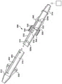
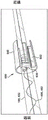
As shown in fig. 14 and 15, in some embodiments, the fluid system 10 can include a magnetic drive system 500 operable to actuate the gap wire assembly 400. One form of actuation provided by magnetic drive system 500 is translation of gap wire assembly 400 back and forth through medical tube 100 along axis X of medical tube 100. Another form of actuation provided by magnetic drive system 500 is rotation of clearance wire assembly 400 within medical tube 100 about axis X. The magnetic drive system 500 may correspond to U.S. patent nos.: 7,951,243, the contents of which are incorporated herein by reference in their entirety as display B.
The magnetic drive system 500 includes a guide tube 510, the guide tube 510 having a tip 512, the tip 512 being fluidly coupled to the proximal end 104 of the medical tube 100, and a proximal end 514, the proximal end 514 being fluidly coupled to a suction source, such as, for example, the receptacle 202 of the drain assembly 200 shown in fig. 2. The guide tube 510 defines a guide tube channel 516 and an outer circumference 518.
The drive system 500 further includes a magnetic guide 530, the magnetic guide 530 having one or more first magnetic elements 532, the first magnetic elements 532 being fixedly coupled to the guide wire 402 of the gap wire assembly 400. The first magnetic element 532 may be a permanent magnet such as, for example, a neodymium magnet (N5-N52). Alternatively, the first magnetic element 532 may be a metal element with magnetic properties, which is not necessarily a permanent magnet. As used herein, a metal element is magnetic if it can be attracted by a permanent magnet by magnetic force.
The drive system 500 further comprises a shuttle member 540, the shuttle member 540 being disposed on the outer circumference 518 of the guide tube and preferably in contact with the outer circumference 518 of the guide tube 510. The shuttle member 540 has a through bore, preferably having a diameter substantially corresponding to the outer periphery 518, such that the shuttle member 540 may slidably and smoothly translate along the length of the guide tube 510, wherein the guide tube 510 is received through its bore. Shuttle member 540 includes one or more second magnetic elements 542 embedded or enclosed within a shuttle housing 544. Alternatively, the second magnetic element 542 may form all or a portion of the housing 544. Alternatively, shuttle member 540 may consist of only second magnetic element 542. In the illustrated embodiment, the second magnetic element 542 is provided in the form of a ring, with the guide tube 510 passing through an opening at the center of each of the rings. As with the first magnetic element 532 described above, the second magnetic element may be a permanent magnet or a metal element having magnetic properties, which need not necessarily be a permanent magnet. The magnet may be coated or plated with nickel, gold, epoxy, PTFE, parylene or other metals, alloys, polymers, or combinations thereof. The coating may act as a barrier to prevent degradation of the magnet material, prevent leaching of metal from the magnet, provide a biocompatible and/or anti-thrombogenic surface and/or provide a low friction surface for sliding over the guide tube.
The first and second magnetic elements 532, 542 of the magnetic guide 530 and the shuttle member 540 are magnetically aligned relative to each other to generate a magnetic force between the first and second magnetic elements 532, 542 that passes through the wall of the guide tube 510 to magnetically couple the shuttle member 540 to the magnetic guide 530. Thus, sliding or translating the shuttle member 540 along the length of the guide tube 510 causes corresponding translational movement of the magnetic guide 530 magnetically coupled thereto, and of the guidewire 402 fixedly coupled to the magnetic guide 530. Accordingly, the shuttle member 540 may be translated along the guide tube 510 to move the guidewire 402 of the gap wire assembly 400 through the medical tube 100. Further, rotation of the shuttle member 540 tube may provide rotation of the gap wire assembly 400.
Preferably, the first and second magnetic elements 532, 542 have north and south polarities that are axially aligned relative to the longitudinal axis of the guide tube 510, but in some examples, the first and second magnetic elements 532, 542 may have north and south polarities that are radially aligned. It has been found that magnets having axially aligned polarities can provide a suitable attractive force between first magnetic element 532 and second magnetic element 542 to keep magnetic guide 530 and shuttle member 540 in series while translating shuttle member 540 along the length of tube 510 without unduly increasing friction as they translate along tube 510.
In some examples, drive system 500 further includes a distal holding member 526a and a proximal holding member 526b that are fixedly coupled to guide wire 402 on opposite sides of magnetic guide 530. Distal retention member 526a and proximal retention member 526b are preferably sized such that they cannot pass through distal end 512 and proximal end 514 of guide tube 510, respectively, thereby retaining magnetic guide 530 and the relevant region of guide wire 402 within guide tube 510. Thus, distal retention member 526a and proximal retention member 526b may limit the distance translatable by guidewire 402 through medical tube 100. Further, in some examples, the drive system 500 may include one or more shuttle stops 550 coupled to the outer circumference 518 of the guide tube 510 that may prevent the shuttle member 540 from translating beyond the shuttle stop 550 and thereby inhibit translation of the guidewire 402 further through the medical tube 100.
The shuttle member 540 of the drive system 500 may be translated along the guide tube 510 directly by hand or with a separate drive mechanism. For example, as shown in FIG. 16, drive system 500 may include a lead screw 562 and a motor 564, motor 564 being operable to rotate lead screw 562. In this example, shuttle member 540 may include a coupling portion 566 having a threaded bore extending at least partially therethrough that threadably receives lead screw 562. When the motor 564 is operated to rotate the lead screw 562, the shuttle member 540 will translate along the lead screw 562 and thus along the guide tube 510 of the drive system 500, thereby moving the guide wire 402 of the gapped wire assembly 400. The direction of translation will depend on the direction of rotation of lead screw 562. Preferably, the motor 564 is operable to rotate the lead screw 562 in clockwise and counterclockwise directions such that the motor 564 is operable to move the guide wire 402 of the gap wire assembly 400 forward and backward. The lead screw may be a standard threaded rod and may have a thread design commonly used for lead screws, such as acme threads.
In some examples, one or more electromagnetic linear actuators may be coupled to the shuttle member 540 to translate the shuttle member 540 in a linear motion along the guide tube 510. Such actuators are generally known in the art and may be coupled to a shuttle member 540 as shown in fig. 17. In this example, drive system 500 includes a cradle 566 having a nest 568, with shuttle member 540 received in nest 568. Nest 568 may receive shuttle member 540 using a number of mechanical fits, such as, for example, a releasable snap fit, a slip fit, an interference fit, or a compression fit. Alternatively, cradle 566 may have one or more posts, each post fitting into a corresponding female fitting on shuttle member 540, or vice versa. Other means for mechanically securing shuttle member 540 to carrier 566 may be used, such as, for example, a strap, zipper strip, clamp, or housing at least partially enclosing shuttle member 540. Alternatively, the cradle 566 may have a magnetic element, such as a permanent magnet or an electromagnet, that is directly coupled to the magnetic guide 530, thereby eliminating the need for the shuttle member 540. The cradle 566 may be coupled to (e.g., be a part of) and actuatable by a linear actuator to cause translation of the gapping wire assembly 400 within the guide tube 510, and thus translation of the gapping member within the medical tube 100. For example, the cradle 566 may be coupled to an actuator 570, the actuator 570 having a lead screw 572 or a ball rotated by a motor to drive the cradle 566. The motor may be a DC or AC motor. It may be a stepper motor or a servo motor. The cradle 566 may also be coupled to a belt driven actuator, wherein the cradle 566 is mounted on a belt that is under tension and driven by a motor. The cradle 566 may have bearings that ride along the track. Such systems may employ encoders and/or limit switches (such as proximity switches, reed and/or hall effect sensors) and a suitable control system to actuate the cradle 566 between two or more positions, thereby causing the gap member within the medical tube 100 to actuate.
In still other examples, the cradle 566 may be coupled to one or more pneumatic actuators to actuate the cradle 566 and shuttle member 540 in a linear motion along the guide tube 510.
In still other examples, the drive system 500 may include a worm drive mechanism, wherein a spur gear is rotated by a motor. The spur gear may threadably engage a lead screw that is fixed relative to the shuttle member 540 such that rotation of the spur gear will translate the lead screw through the spur gear and thus translate the shuttle member 540 in a linear motion along the guide tube 510.
The magnetic drive system 500 may include a variety of different drive mechanisms operable to translate the shuttle member 540 along the guide tube 510 and thus translate the guide wire 402 of the interstitial wire assembly 400 through the medical tube 100. Further, any of the drive mechanisms discussed above may be operably connected to a control system, such as, for example, control system 300 described above, to automatically control the drive mechanism. In particular, the controller 302 of the control system 300 may be operatively coupled to the actuator/motor of the drive mechanism and may be configured to selectively operate the actuator/motor according to a particular program and/or in response to a parameter detected by the sensor 306 of the control system 300.
Referring to fig. 18, in some embodiments, the fluid system 10 may include an induction motor drive system 600 operable to rotate the gap wire assembly 400 within the medical tube 100. The induction motor drive system 600 includes a rotor 630 disposed within a tube portion 632, in this example, corresponding to a portion of the medical tube 100. In other examples, tube portion 632 may correspond to a guide tube or some other tube that is fluidly coupled to proximal end 104 of medical tube 100. The rotor 630 is fixedly coupled to the guide wire 402 of the gap wire assembly 400 such that rotation of the rotor 630 will fixedly couple a portion of the guide wire 402 thereto for rotation with the rotor 630. In the example shown, the rotor 630 is fixedly coupled to the proximal end of the guidewire 402, but in other examples, the rotor 630 may be fixedly coupled to a more distal portion of the guidewire 402. The rotor 630 may be a wound or squirrel cage rotor.
The induction motor driving system 600 further includes a shuttle member 640, the shuttle member 640 being disposed on an outer circumference of the pipe portion 632 with the rotor 630 located therein. Shuttle member 640 includes a stator 642 embedded or enclosed within shuttle housing 644, preferably slightly spaced from tube portion 632 such that an air gap will exist between stator 642 and rotor 630. In some examples, shuttle member 640 may consist only of stator 642.
The stator 642 of the shuttle member 640 is aligned with the rotor 630 within the tube portion 632 such that when an AC current is passed through the windings of the stator 642, a rotating magnetic field will be generated which causes the rotor 630 within the tube portion 632 to rotate, thereby rotating the portion of the guide wire 402 fixedly coupled thereto. The rotational speed may be adjusted by adjusting the frequency of the AC current supplied to the stator 642.
The stator 642 of the induction motor drive system 600 may be operably connected to a power source (e.g., a controller) configured to selectively provide AC current to the stator 642. For example, the stator 642 may be operably connected to a controller 302 of the control system 300 described above, which controller 302 may selectively provide AC current to the stator 642 to selectively operate the induction motor drive system 600 and rotate the gap wire assembly 400 in any of the manners described above. In particular, the controller 302 may be configured to selectively operate the induction motor drive system 600 according to a particular program and/or in response to parameters detected by the sensors 306 of the control system 300.
In some examples, the induction motor drive system 600 may be configured similar to the magnetic drive system 500 such that the shuttle member 640 of the induction motor drive system 600 may translate along the tube portion 632 to translate the guidewire 402 within the medical tube 100. In such examples, the shuttle member 640 of the induction motor drive system 600 may likewise be manually driven or driven by any of the drive mechanisms described above in conjunction with the magnetic drive system 500.
Turning to fig. 19A-E, in some embodiments, the fluid system 10 can include a spool drive system 700 operable to translate the interstitial wire assembly 400 within the medical tube 100. In some examples, the spool drive system 700 may correspond to U.S. patent application publication nos.: 2015/0231313, the contents of which are herein incorporated by reference in their entirety as display C. In one example, as shown in fig. 19A-D, the spool drive system 700 includes a spool housing 702 having an inlet 704, the inlet 704 being coupleable to the proximal end 104 of the medical tube 100. The spool housing 702 includes a first portion 706 and a second portion 708 that can be coupled together (e.g., by fasteners, welding, adhesives, etc.) to form a housing. Within the spool housing 702 is a spool 710 rotatable about an axis. Further, spool housing 702 defines a track 712, which track 712 is spaced apart from spool 710 and extends at least partially around the circumference of spool 710, following a line of curvature substantially similar to spool 710.
The guide wire 402 of the interstitial wire assembly 400 may be fed through the inlet 704 of the spool housing 702 and coupled to the spool 710 (e.g., by set screws, adhesives, press-fit, etc.) such that rotation of the spool 710 about the axis of the spool causes the guide wire 402 to wind or unwind about the spool 710 and move between an advanced state and a retracted state. In some embodiments, the tip of the guidewire 402 can be positioned within the medical tube 100. If the spool 710 is rotated in one direction, the guidewire 402 will be wound around the spool 710, causing the guidewire 402 (and any clearance members coupled thereto) to translate (i.e., retract) away from the tip 102 of the medical tube 100. Conversely, if the spool 710 is rotated in the opposite direction, the guidewire 402 will be deployed around the spool 710, causing the guidewire 402 (and any clearance members coupled thereto) to translate (i.e., advance) toward the tip 102 of the medical tube 100. Thus, rotation of the spool 710 may control translation (actuation) of the wire assembly 400 within the medical tube 100.
As the spool 710 rotates, the track 712 of the spool housing 702 will help guide the guidewire 402 onto the spool 710 or out of the spool 710. Additionally, the track 712 can help maintain the guidewire 402 in a wrapped state and prevent the guidewire 402 from unwinding due to the stiffness of the guidewire 402. However, friction from the track 712 can provide resistance to the guidewire 402, which in some examples can substantially prevent winding or unwinding of the guidewire 402 on or off of the spool 710. Accordingly, the track 712 can include one or more aspects that can help reduce friction applied to the guidewire 402 by the track 712.
For example, in the example shown, the track 712 includes a groove surface 714, the groove surface 714 extending at least partially around a circumference of the spool 710, and includes grooves 716, the grooves 716 being circumferentially spaced around the spool 710. The groove 716 of the track 712 will reduce the surface area of the track 712 that engages the guidewire 402 (as compared to a track 712 having a non-grooved surface), thereby reducing the amount of friction applied to the guidewire 402 by the track 712.
In another example, the surface 712 will include ridges (as opposed to grooves) that are circumferentially spaced about the spool 710. The ridges of the track 712 will contact the guidewire 712 (as opposed to the entire track surface), thereby reducing the surface area of the track 712 that engages the guidewire 402 and the amount of friction applied to the guidewire 402 by the track 712.
In some examples, the track 712 can include wheels 720 that are circumferentially spaced about the spool 710 and that will rotatably engage the guidewire 402, as shown in fig. 19E. The rotatable engagement of the wheel 720 may provide less resistance to the guidewire 402 engaging a rigid surface than in other examples. In such examples, the wheel 720 may be biased toward the spool 710 with a spring or other biasing structure to help maintain the wheel 720 in engagement with the guidewire 402.
Also in some examples, one or more components of the track 712 may include or be coated with a low friction material, such as, for example, a hydrophilic coating, a hydrogel, parylene, PTFE, FEP, a low friction polymer, or a low friction silicone. For example, the groove surface 714 and/or the wheel 720 described above may include or be coated with such low friction materials. Or the track may have a lining of such material, for example, thin strips of stainless steel sheet (or flat wire) may be coated with PTFE and mounted (coupled) with the housing to form a track surface that interacts with the wire. The strap may be held in place by various means such as adhesives, clamps, or it may be made of spring tempered steel and secured to the housing by spring tension. It may also be held in place by other means.
In one configuration, the track 712 consists of ball bearings contained within an inner race and an outer race. In this embodiment, the wire is engaged with a ball bearing, allowing low friction movement of the wire.
In some examples, the spool drive system 700 may include a motor 722, the motor 722 operable to rotate a spool 710 within the spool housing 702 and cause translation of a wire assembly 440 within the medical tube 100. As shown in fig. 19D, the motor 722 may be disposed outside of the spool housing 702 and may be rotatably coupled to the spool 710 within the spool housing 702 by a gearing mechanism 724. In the illustrated embodiment, the transmission 724 includes a first bevel gear 726 secured to a shaft 728 of the motor 722 and a second bevel gear 730 secured to a shaft 732 of the spool 710, the second bevel gear 730 threadingly engaging the first bevel gear 726. However, the transmission 724 may include other types and/or combinations of gears and shafts, in other examples, to rotatably couple the motor 722 to the spool 710. Indeed, in some examples, the transmission 724 may simply consist of a shaft that is common to the motor 722 and the spool 710.
A portion of the drive mechanism 724, such as the shaft 732 of the spool 710, will pass through an aperture 736 (shown in fig. 19B) in the spool housing 702. In some examples, a seal may be provided that may allow the drive mechanism 724 to pass through the aperture 736 while inhibiting the transfer of liquids and other materials through the aperture 736. Thus, a sterile zone within the spool housing 702 may be maintained relative to the environment outside of the spool housing 702. Additionally or alternatively, the spool drive system 700 may include a motor housing 740 (shown in fig. 19A-B) that may be coupled to the spool housing 702 (e.g., via fasteners) to enclose the motor 722 and the drive train 724. Motor housing 740 may be sealed relative to spool housing 702 to provide a sterile environment around motor 722 and gear train 724, with gear train 724 sealed from the environment outside of motor housing 740.
In some examples, the motor 722 may be battery powered. Further, the motor 722 may be operably connected to the controller 302 of the control system 300 described above, and the controller 302 may selectively operate the motor 722 to translate the gap wire assembly 400 in any of the manners described above. In particular, the controller 302 may be configured to selectively operate the motor 722 according to a particular program and/or in response to parameters detected by the sensors 306 of the control system 300. Further, control system 300 and controller 302 may be located at least partially within motor housing 740, as shown in fig. 19B.
The spool housing 702 may be separated from the blood channel by a seal that allows a vacuum to be maintained in the fluid path. The spool housing 702 may need to be sterile, with seals to maintain sterility from the motor housing. The seal may also maintain pressure as a safe (backup) device against pressure loss. The seal may take various forms, such as a rubber seal or a weld. In case the rotational axis or the translation line passes through a seal, it needs to be a suitable type of seal. In an alternative embodiment, the motor housing 740 may be removably coupled to the spool housing 702 such that it may be reused and the spool housing 702 discarded.
Turning to fig. 20, in a variation of the spool drive assembly 700 described above, the spool 710 is replaced with a roller 750 and the track 712 is replaced with a coiled tube 752. In this example, the spool drive assembly 700 has an inlet tube 754 with a cutout region 756 and the roller 750 is disposed within the cutout region 756 and is rotatable relative to the spool housing 702. The guide wire 402 of the gapped wire assembly 400 can be fed through the inlet 704 of the spool housing 702 such that a portion of the guide wire 402 will be located between (and preferably engage) the outer circumference of the roller 750 and the inner surface of the inlet tube 754. The roller 750 may then be rotated in one direction (e.g., counterclockwise) to pull the guidewire 402 proximally (i.e., away from the patient) through the space between the roller 750 and the inner surface of the inlet tube 754, thereby causing the guidewire 402 to be retracted through the medical tube 100. Alternatively, the roller 750 may be rotated in the opposite direction (e.g., clockwise) to push the guidewire 402 distally (i.e., toward the patient) through the space between the roller 750 and the inner surface of the inlet tube 754, thereby causing the guidewire 402 to advance through the medical tube 100. The roller 750 may be rotated similar to the spool 710 using the motor 722 and control system 300 described above.
When the coiled tubing 752 is pulled proximally into the spool housing 702 by the rollers 750, the coiled tubing 752 will accommodate the guidewire 402. The coil 752 may be made of a low friction material. Various polymers may be used, such as PTFE, FEP, or other low friction polymers. However, it should be understood that the tube 752 may have other configurations in other examples, such as, for example, a straight configuration. Further, in some embodiments, the coiled tubing 752 may be integral with the spool housing 702.
Turning to fig. 21, in some embodiments, the fluid system 10 may include a conveyor drive system 800, the conveyor drive system 800 operable to convey a conveyor line assembly 400, such as described above in connection with fig. 12A-B. The conveyor drive system 800 includes a delivery tube 802, the delivery tube 802 having a distal end 804, the distal end 804 coupled to the proximal end 104 of the medical tube 100 and a proximal end 806, the proximal end 806 fluidly coupled to a suction source, such as, for example, the receptacle 202 of the drain assembly 200 shown in fig. 2. The pulley 442 at the proximal end of the wire assembly 400 is located within the conveyor tube 802 and is arranged such that the axis of rotation of the pulley 442 intersects the central axis of the conveyor tube 802 and is perpendicular to the central axis of the conveyor tube 802.
A portion of the transmission 814 (e.g., the shaft 822 of the pulley 442) will pass through the aperture 826 in the conveyor tube 802. In some examples, a seal can be provided to allow the transmission 814 to pass through the aperture 826 while inhibiting liquid and other materials from transferring through the aperture 826. Thus, a sterile zone within the conveyor tube 802 may be preserved relative to the environment outside the conveyor tube 802. Additionally or alternatively, the drive system 800 may include a housing 830 that will enclose the motor 812 and the transmission 814. The housing 830 may have a sealed inlet 834 and a sealed outlet 836 through which the conveyor tube 802 may extend, such that a portion of the conveyor tube 802 passing through the transmission 814 is also enclosed within the housing 830. Thus, the housing 830 can provide a sterile environment around the motor 812, the transmission 814, and the conveyor tube 802, with the conveyor tube 802 being sealed from the environment outside the housing 830.
The motor 812 of the drive system 800 can be operated to rotate the pulley 442 within the conveyor tube 802, which in turn will cause the transmission of the wire assembly 440 around the pulley 442. In some examples, the pulley 422 may include teeth around its circumference that, as the pulley 422 rotates, will engage the belt 440 and/or the clearance member 444 of the wire assembly 400 to facilitate the conveyance of the wire assembly 400. In other examples, the pulley 422 may simply comprise a smooth circumferential surface and the wire assembly 400 will be tensioned around the circumferential surface such that rotation of the pulley 422 will convey the wire assembly 400 through friction between the wire assembly 400 and the circumferential surface.
The motor 812 may be operated such that the belt 440 of the wire assembly 400 is continuously or intermittently conveyed around the pulley 442. Further, the motor 812 may be operated such that the belt 440 always travels in the same direction (e.g., clockwise) or in alternating directions (e.g., first clockwise and then counterclockwise). In some examples, the motor 812 may be operably coupled to the controller 302 of the control system 300 described above, and the controller 302 may selectively operate the motor 812 to convey the gap wire assembly 400 in any of the manners described above. In particular, the controller 302 may be configured to selectively operate the electric motor 812 according to a particular program and/or in response to parameters detected by the sensors 306 of the control system 300.
In some examples, the conveyor drive system 800 will include one or more brushes 838 within the conveyor tube 802, which brushes 838 will engage the gapping members 444 of the gapping wire assembly 400 and/or the belt 440 as the belt 440 is conveyed around the pulleys. This can help clean the gap wire assembly 400 and remove any material that may collect on the gap wire assembly 400. The brush 838 may be heparin coated.
Fig. 22A and 22B illustrate another example conveyor drive system 800 that is operable to convey a conveyor line assembly 400, such as described above in connection with fig. 13. The conveyor drive system 800 includes a housing 852 having two ports 854, each port 854 fluidly coupled to one of the two proximal end portions 114 of the medical tube 100. The housing 852 may also include a third port 856 that is fluidly coupled to a suction source, such as, for example, the reservoir 202 of the drain assembly 200 shown in fig. 2. The drive system 800 disposed within the housing 852 may also include a rotatable sprocket 858. In addition, the housing 852 can define a track 862 that extends partially (e.g., halfway) around a perimeter of the sprocket 858 and is coaxial with the sprocket 858.
The housing 852 and the medical tube 100 together will form a continuous loop 118 to which the band 440 of the wire assembly 400 is transferred to. More specifically, the band 440 will extend through the medical tube 100, through the two ports 854 into the housing 852, and wrap around the sprocket 858 along the track 862.
A portion of the transmission 868 will pass through the aperture 870 in the housing 852. Preferably, a seal may be provided that may allow the transmission 868 to pass through the aperture 870 while inhibiting liquid and other materials from transferring through the aperture 870. Accordingly, a sterile zone within the housing 852 can be maintained relative to the environment external to the housing 852.
The motor 866 of the drive system 800 may be operated to rotate the sprocket 858 within the housing 852, which in turn will result in the transmission of the wire assembly 400 around the sprocket 858. In this example, the sprocket 858 includes a spindle 872 that, when the sprocket 858 rotates, the spindle 872 will engage the clearance members 444 of the wire assembly 400 to facilitate transport of the wire assembly 400. In other examples, the sprocket teeth 858 can include teeth around their perimeter that will engage the bands 440 and/or clearance members 444 of the wire assembly 400 as the sprocket teeth 858 rotate to facilitate transport of the wire assembly 400. In other examples, the sprocket 858 may simply include a smooth circumferential surface and the wire assembly 400 will be tensioned around the circumferential surface such that rotation of the sprocket 858 will convey the wire assembly 400 by friction between the wire assembly 400 and the circumferential surface.
The motor 866 may be operated such that the wire assembly 400 is continuously or intermittently routed around the sprocket 858. Further, the motor 866 can be operated such that the belt 440 is always conveyed in the same direction (e.g., clockwise) or in alternating directions (e.g., first clockwise and then counterclockwise). In some examples, the motor 866 can be operably connected to the controller 302 of the control system 300 described above, and the controller 302 can selectively operate the motor 866 to convey the gap wire assembly 400 in any of the manners described above. In particular, the controller 302 can be configured to selectively operate the motor 866 according to a particular program and/or in response to parameters detected by the sensors 306 of the control system 300.
The various drive systems 500, 600, 700, 800 described above may be utilized to move the gap wire assembly 400 within the medical tube 100 in accordance with one or more of the manners described above. In particular, the drive systems 500, 600, 700, 800 may all be used to translate, rotate, and/or deliver the gapping wire assembly 400 within the medical tube 100. Further, the drive system 500, 600, 700, 800 may be operably coupled to a controller, such as, for example, the controller 302 of the control system 300 described above, to automatically control movement of the gap wire assembly 400 within the medical tube 100. Preferably, drive system 500, 600, 700, 800 may be configured (e.g., sized and shaped) so as to be hand-held and, in some examples, disposable. If the drive system is electric, a rechargeable battery may be used to power the motor. Further, in some examples, the electric motor may be powered by a power assembly that is separate from the main body of the drive system and connected to the main body via wiring, as shown in fig. 23. By separating the power assembly, the power assembly can be replaced/recharged without having to disassemble the body of the drive system.
For embodiments in which fluid system 10 has a drive system (e.g., one of drive systems 500, 600, 700, 800) configured to translate or convey gapline assembly 400 along channel 106 of medical tube 100, the drive system may be configured to allow for calibration of the distance translated/conveyed by gapline assembly 400. For example, fig. 24 illustrates an exemplary spool drive system 700 configured to translate the gap wire assembly 400 along the channel 106 of the medical tube 100. The spool drive system 70 may be operated to advance the gapping wire assembly 400 toward the distal end 102 of the medical tube until the gapping wire assembly 400 reaches a position where it is desired to be in a fully advanced position. For example, the spool drive system 700 may be operated to advance the gap wire assembly 400 toward the distal end 102 of the medical tube 100 until the distal end of the gap wire assembly 400 reaches the distal end 102 of the medical tube 100. The position of the gap wire assembly 400 can be detected using various means, such as through calculation steps of a stepper motor, hall sensor, optical encoder, and the like. A button, switch, touch screen, or some other structure may then be engaged (e.g., pressed) by the user to send a signal to a controller (e.g., controller 302) indicating that the gap wire assembly 400 is in the fully advanced position. The controller may then store the position in memory to calibrate the fully advanced position of the drive system 700.
Similarly, the spool drive system 700 can be operated to retract the gap wire assembly 400 toward the proximal end 104 of the medical tube 100 until the gap wire assembly 400 reaches a position where a fully retracted position is desired. For example, the spool drive system 700 may be operated to retract the gap wire assembly 400 toward the proximal end 104 of the medical tube 100 until the end of the gap wire assembly 400 is proximate to a set of holes 110 in the end portion of the medical tube 100. The position of the gap wire assembly 400 can be detected using various means, such as through calculation steps of a stepper motor, hall sensor, optical encoder, and the like. A button, switch, touch screen, or some other structure may then be engaged (e.g., pressed) by the user to send a signal to a controller (e.g., controller 302) indicating that the gap wire assembly 400 is in the fully retracted position. The controller may then store the position in memory to calibrate the fully condensed position of the drive system 700.
Once the fully advanced and fully retracted positions are calibrated, the controller may operate the drive system 700 such that the gap wire assembly 400 translates within the medical tube 100 between the fully advanced and fully retracted positions.
It should be appreciated that any of the drive systems 500, 600, 800 described above may also be similarly calibrated to the drive system 700 shown in FIG. 24. Further, in some examples, the drive system 500, 600, 700, 800 may be configured to automatically calibrate without requiring a user to indicate when the gap wire assembly 400 has reached a fully advanced position and/or a fully retracted position. For example, in some examples, each drive system 500, 600, 700, 800 may include one or more sensors (e.g., sensor 306) that can detect when its associated gap wire assembly 400 has reached a fully advanced position and/or a fully retracted position and send a signal to its associated controller indicating the position of the wire assembly so that the controller can store the position in memory and calibrate the drive system.
Turning now to fig. 25, a Y-coupler 900 will be described that may be used to couple medical tube 100 to various structures, such as, for example, drive systems 500, 600, 700, 800 described above. The Y-coupler 900 includes a first tube portion 902a having an end 904a, the end 904a being fluidly coupled to the proximal end 104 of the medical tube 100. The Y-coupler 900 also includes a second tube portion 902b having an end 904b, the end 904b being fluidly coupled to a suction source, such as, for example, the container 202 of the drain assembly 200 shown in fig. 2. In addition, Y-coupler 900 also includes a third tube portion 902c having an end 904c, where end 904c may be coupled to another structure, such as, for example, an inlet or port of one of drive systems 500, 600, 700, 800 described above. For example, fig. 19A shows a Y-coupler 900 in which end 904c is coupled to the spool drive system 700 described above.
Y-coupler 900 defines a channel 910 that provides fluid communication between end 904a of first tube portion 902a and end 904b of second tube portion 902. Thus, the channel 910 may provide a path for material to be aspirated from the medical tube 100 and expelled to an aspiration source.
The Y-coupler 900 also includes a hole 912, the hole 912 extending through the third tube section 902c and opening into the channel 910. The aperture 912 is sized to allow the guide wire 402 of the gap wire assembly 400 to pass through the aperture 912. Thus, when medical tube 100 is connected to Y-coupler 900, guidewire 402 may extend from within medical tube 100, through Y-coupler 900, and into any structure coupled to end 904c of Y-coupler 900.
In some examples, at least a portion of the aperture 912 (e.g., portion 912a) has a diameter that is slightly larger than the diameter of the guidewire 402. This will allow the guidewire 402 to pass through the aperture 912 but inhibit liquids (e.g., bodily fluids) and other materials from passing through the aperture 912. By inhibiting liquids and other materials from passing through the aperture 912, the vacuum (and medical tube 100 in liquid communication therewith) passage 910 within the passage 910 may be maintained and any pressurized environment in communication with the end 904c of the third tube portion 902c isolated. In addition, liquids (e.g., bodily fluids) and other materials passing through the channel 910 may be inhibited from passing through the aperture 912 into any structure coupled to the end 904c of the third tube portion 902 c.
Additionally or alternatively, in some examples, one or more cylindrical sleeves 914 may be disposed within the aperture 912, and the guidewire 402 may pass through the aperture 912. Each sleeve 914 may comprise, for example, Delrin (Delrin), ceramic, stainless steel, PEEK, PTFE, closed cell polyurethane foam, filled fibers, and/or other materials.
Additionally or alternatively, in some examples, one or more cylindrical wipers may be disposed within the apertures 912 to inhibit liquids (e.g., bodily fluids) and other materials from passing through the apertures 912. For example, a cylindrical wiper 916 may be disposed within the aperture 912, and the guidewire 402 may pass through the aperture 912. The wiper 916 preferably comprises a porous material that can absorb any liquid that attempts to pass through the wiper 916 through the guidewire 402. For example, the wiper 916 may include a foam, such as open or closed cell polyurethane foam, polyethylene foam, hydrophilic foam, hydrogel, polyester weave, or the like. In other examples, wiper 916 may include a silicone rubber membrane.
Additionally or alternatively, in some examples, one or more cylindrical lubricators 918 may be disposed within the bore 912 that will lubricate the guidewire 402 as the guidewire 402 passes through the lubricators 918. Each lubricator may include, for example, medical grade silicone oil, heparin solution, PTFE lubricant, mineral oil, petrolatum, or the like.
Additionally or alternatively, in some examples, one or more valves 920 may be disposed within the apertures 920, which may be actuated to selectively open and close liquid communication through the apertures 912.
In the example shown, the Y-coupler 900 includes a combination of the smaller diameter portion 912a, sleeve 914, wiper 916, lubricator 918, and valve 20 described above. In such examples, the four elements are preferably arranged such that the smaller diameter portion 912a is distal to the sleeve 914, the sleeve 914 is distal to the wiper 916, the wiper 916 is distal to the lubricator 918, and the lubricator 918 is distal to the valve 920, although other arrangements and/or combinations of these elements are possible in other examples.
Additionally, a seal may be used at the junction of fluid path 910 and channel 912 to limit or eliminate the ingress of liquid and debris into the channel. The seal may be an elastomeric gasket, such as a dome slit valve or flat seal, that allows passage of the guide wire and, in some configurations, the clearance member.
Turning to fig. 26, in some examples, the Y-coupler 900 includes bristles 920 within the aperture 912, which bristles 920 will mechanically remove material (e.g., clot) from the guidewire 402 as it translates through the aperture 912. Removal of material occurs when the vacuum source is turned off to encourage removal of such material toward the drain tank. A valve may be provided to separate the bristles 920 from the flow path to prevent blood clots from collecting on the bristles 920.
Fig. 27 shows another exemplary Y-coupler 900 having a hole 912 that mates with the guidewire 402, the hole 912 for scraping large clots and debris from the guidewire, a sleeve 914 that may be a rigid material (e.g., Delrin @, polycarbonate, etc.) or an elastomeric material such as silicone rubber to provide a seal to separate fluid paths that may be under vacuum and spool compartments that may be under atmospheric pressure, and to wipe excess blood and other fluids from the wire to reduce their potential for being carried into the spool compartments. The star coupling (y-connection) may also have a wiper 916, and the wiper 916 may be made of open-cell polyurethane foam, hydrophilic foam, or other hydrophilic material (e.g., hydrogel) or other medium, which is preferably porous. In addition, channel 910 includes two interacting linear channels (as opposed to the curved channels shown in fig. 25 and 26).
Turning now to fig. 28, it will now be described that the elastomeric restoring feature may facilitate translation of the gap wire assembly 400 through the medical tube 100. More specifically, in some examples, the medical tube 100 may include a resilient member 120 extending within the channel 106 that is fixedly coupled at a distal end 122 thereof to a portion (e.g., the distal end 102) of the medical tube 100. The resilient member 120 may be further fixedly coupled at its proximal end 124 to a portion of the gap wire assembly 400 (e.g., the guide wire 402). The elastic member 120 may be configured such that when the gap wire assembly 400 is retracted through the medical tube 100 towards its proximal end 104, the elastic member 120 will be stretched by the gap wire assembly 400. In this stretched state, the elastic member 120 will bias (e.g., pull) the gap wire assembly 400 toward the tip 102 of the medical tube 100. Such biasing from the resilient member 120 can help maintain the guidewire 40 of the interstitial wire assembly 400 in a straight configuration within the medical tube 100, particularly during subsequent advancement of the interstitial wire assembly 400 back toward the tip 102 of the medical tube 100.
Turning now to fig. 29, in some examples, medical tube 100 can include a tapered seat 123 that can facilitate the destruction of material that may accumulate on the clearance members of clearance wire assembly 400. A tapered seat 128 extends radially inward and in a proximal direction from the distal end 102 of the medical tube 100 within the passageway 106. In this embodiment, the gap wire assembly 400 includes a gap member in the form of a ring 450. During or after use, the gap wire assembly 400 may be advanced toward the tip 102 of the medical tube 100 until the tapered seat 128 protrudes through the gap member ring 450, thereby destroying any material that may accumulate within the ring 450.
As described above, the gap wire assembly 400 may be moved within the medical tube 100 in order to break up material that accumulates within the medical tube 100. Preferably, the inner surface of medical tube 100 will be coated with a layer of material that can reduce the frictional properties of the medical tube, thereby reducing any resistance that medical tube 100 applies to movement of gap wire assembly 400 within medical tube 100. Example materials that may be applied to the inner surface of medical tube 100 are hydrophilic coatings, hydrogels, PVP, parylene C, parylene N, PTFE, Pebax, and low friction silicones. However, in some examples, it may be desirable for some portions of the inner surface of the medical tube not to be coated with a friction reducing layer.
For example, as described above, in some examples, medical tube 100 is flowably coupled to various structures, such as, for example, drainage assembly 200 described above and/or drive systems 500, 600, 700, 800 described above. To fluidly couple the medical tube 100, a fitting such as, for example, a hose barb may be used that is insertable into an end of the medical tube 100. The end of the medical tube 100 may then be collapsed to provide a liquid seal between the fitting and the medical tube 100. However, if a friction reducing agent is applied to the inner surface of the medical tube, where the medical tube 100 engages the fitting, a tight liquid seal may not be achieved and the fitting may disengage from the medical tube 100.
Accordingly, one aspect of the present invention relates to a method of applying a friction reducing agent to an inner surface of a medical tube 100, wherein a portion of the inner surface of the medical tube (e.g., one or both ends or a portion therebetween) is to be covered prior to application of the agent. The inner surface portion may be masked using a masking material applied to the surface portion, for example with an adhesive. Alternatively, a cylindrical plug may be inserted within medical tube 100 having an outer cylindrical wall with a diameter substantially matching the diameter of the inner surface and a length corresponding to the length of the tube ID, wherein it is desired not to apply a coating. In one example, the plug is expandable and may be made of an elastic material such as rubber. In another example, the plug may have an O-ring that engages and seals the ID of the tube. In one example, the plug is a tube open at its center for the passage of gas or liquid, allowing the coating to enter from both sides of the tube. Such a stopper may block the portion of the inner surface engaged by the stopper from exposure to the medicament. Once the desired portion of the inner surface is covered, a friction reducing agent (e.g., parylene) may be applied to the inner surface of medical tube 100 to coat the remaining portion of the inner surface that is not covered. After the medicament is applied (and in some examples, cured or dried), the covering device (e.g., plug) may be removed from the medical tube 100.
The above-described method may produce a medical tube 100 having an inner surface partially coated with a friction reducer such that one or more portions (e.g., one or both ends) of the inner surface of the medical tube are not coated with the friction reducer.
It should be understood that the above-described methods may be similarly applied to the outer surface of the medical tube 100 to partially coat the outer surface with a friction reducing agent, particularly such that one or more portions (e.g., one or both ends) of the outer surface of the medical tube are not coated with the friction reducing agent. For example, the outer surface portion may be masked using a masking material applied to the surface portion, for example with an adhesive. Alternatively, a cylindrical ring may be slid over the medical tube 100, the cylindrical ring having an inner cylindrical wall with a diameter substantially matching the diameter of the outer surface and a length corresponding to the length of the OD of the tube, wherein it is desired not to apply a coating. In one example, the ring is expandable and may be made of an elastic material such as rubber. In another example, the ring may have an O-ring that engages and seals the OD of the tube. Such a ring may block exposure of the outer surface portion engaged by the ring to the agent. Once the desired outer surface portion is masked, a friction reducing agent (e.g., parylene) may be applied to the outer surface of medical tube 100 to coat the remaining portion of the unmasked outer surface. After the medicament is applied (and in some examples, cured or dried), the covering device (e.g., plug) may be removed from the medical tube 100.
The fluid system 10 described above may be used to deliver material to and/or remove material from a patient through the medical tube 100 described above. In some aspects, fluid system 10 may be configured to deliver a therapeutic agent to a patient through medical tube 100. For example, fluid system 10 may include a delivery system fluidly coupled to proximal end 104 of medical tube 100 and configured to deliver a therapeutic agent to a patient through medical tube 100, such as, for example, a fluid controlled at a temperature (e.g., body temperature) (e.g., saline), an anti-inflammatory agent, an anti-arrhythmic agent, an infectious agent, a cardiovascular agent, an infectious disease control agent, an anti-inflammatory agent, a cancer treatment agent, an agent that facilitates pleurodesis, an analgesic, or any combination thereof. The delivery system may be operably connected to a controller (e.g., controller 302) of a control system (e.g., control system 300), which may automatically operate the delivery system according to a particular program and/or in response to parameters detected by one or more sensors (e.g., sensor 306) of the control system. In one embodiment, the exact volume of inserted liquid is tracked and subtracted from the total volume drained so that the volume drained is known and it is known whether all liquid was subsequently removed. As shown in fig. 30, in one embodiment, the body space tube has one or more additional lumens in addition to the main lumen. The additional chamber is used for the application of liquid outside the body space tube in order to treat the space around the tube with liquid. In one embodiment, the liquid is contained in a liquid reservoir that is part of the tube gap drive mechanism or liquid collection tank. In one embodiment, the liquid is controlled by a pump. In one embodiment, the liquid is applied by pressure applied to the reservoir, controlled by a liquid restriction or restrictive valve, to maintain a steady volumetric delivery to the body space outside the body space tube. In one embodiment, the lumen of the supplemental tube is the exact length of the body space drainage tube. In another embodiment, the pipe may extend outside the main pipe in one or more directions to transport liquid away from the body space pipe. In one embodiment, the temperature of the liquid is controlled to be above body temperature, the same as body temperature, or below body temperature. In one embodiment, the liquid rate is controlled on a cc/min basis. In one embodiment, fluid administration is monitored and displayed digitally. In one embodiment, the liquid application volume is monitored and subtracted from the total drainage, so the exact amount of drainage recorded is divided into a liquid delivery volume and a liquid drainage volume. In one embodiment, total blood loss is estimated by a formulation that includes the total drainage minus the administration fluid. In one embodiment, if the delivered fluid parameter fails to evacuate, an alarm is provided to prevent unidentified remaining administered fluid. In one embodiment, the removed fluid is analyzed for properties such as pH, hematocrit, redox status, temperature to monitor recovery of the body space from bleeding, infection, inflammation, or other physical properties over time. In one embodiment, this is combined with a medical tube clearance device to prevent application of liquid to spaces that are not adequately drained due to blockage of the body space drain tube from clots or other obstructive material. In one embodiment, the fluid is saline or other physiologically balanced fluid replacement formulation. In one embodiment, the fluid is a pleurodesis-inducing chemical (i.e., talc, tetracycline, doxycycline or other formulation intended to induce sclerosis). In one embodiment, the liquid is an antibiotic, antifungal, or other agent for treating infection. In one embodiment, the agent is an anti-cancer agent for treating tumors. In one embodiment, the liquid is an anti-inflammatory agent, an anti-arrhythmic agent, an anti-fibrinolytic agent, a fibrinolytic agent, or any combination thereof. In one embodiment, the supplemental lumen can be advanced or retracted. In one embodiment, this may be done with a guidewire to prevent or minimize the possibility of internal structural damage.
While the invention has been described in connection with certain embodiments, it is to be understood that the invention is not limited to the embodiments disclosed herein, which are intended to be illustrative rather than restrictive, but includes all modifications and adaptations thereof which may occur to one skilled in the art upon reading the present disclosure and which fall within the spirit and scope of the invention as set forth in the following claims.
Claims (26)
1. A spool drive system for actuating a guidewire, the system comprising:
a spool housing provided with an inlet, said spool being rotatable about its axis to wind and unwind said guidewire on said spool to respectively withdraw or advance said guidewire through said inlet;
a track comprising a grooved surface, the track spaced from and extending at least partially around a periphery of a spool within the spool housing, the track adapted to guide the guidewire onto or off of the spool as the spool rotates; and
a motor housing having a motor disposed therein and operable to advance or retract the guidewire from or into the spool housing through the access opening, the spool housing and motor housing being integrally combined into a single hand held assembly.
2. The spool drive system according to claim 1 wherein said track is adapted to help retain said guidewire on said spool in a wound state preventing deployment thereof that might otherwise result from the stiffness of said guidewire.
3. The spool drive system of claim 1 wherein said recessed surface comprises a plurality of circumferentially spaced grooves opposite a peripheral surface of said spool.
4. The spool drive system of claim 1 wherein said track includes a surface having a plurality of circumferentially spaced ridges opposite a peripheral surface of said spool.
5. The spool drive system according to claim 1 wherein said track includes a plurality of circumferentially spaced wheels opposite a peripheral surface of said spool, said wheels effective to rotatably engage said guide wire as it is wound or unwound on said spool.
6. The spool drive system according to claim 5 wherein said wheel is radially biased toward a peripheral surface of said spool so as to operatively engage said guidewire as said spool rotates.
7. The spool drive system of claim 1 wherein said track includes a plurality of ball bearings defined along a circular path opposite a peripheral surface of said spool.
8. The spool drive system according to claim 1 wherein said track comprises a low friction material or coating to provide a low friction sliding interface between features of said guide wire and said track as said spool rotates.
9. The spool drive system of claim 1 wherein said motor is rotatably coupled to a shaft of said spool, said shaft extending through an aperture between said spool housing and said motor housing, said motor thereby being effective to rotate said spool.
10. The spool drive system according to claim 9 further comprising a battery within said motor housing for providing electrical power to said motor.
11. The spool drive system according to claim 10 further comprising a controller within said motor housing, said controller operably coupled to said motor, said controller configured to operate said motor to actuate said guidewire by rotating said spool.
12. The spool drive system according to claim 11 wherein said controller is configured to selectively operate said motor according to a specific program and/or in response to a sensed parameter communicated to said controller.
13. The spool drive system according to claim 1 further comprising a battery sealed to said hand held assembly for supplying electrical energy to said motor, wherein said hand held assembly is configured to be disposable.
14. The spool drive system according to claim 13 wherein said hand held assembly is sterile.
15. The spool drive system according to claim 1 further comprising a controller within said hand held assembly, said controller operatively connected to said motor, said controller configured to operate said motor to actuate said guidewire by rotating said spool.
16. The spool drive system according to claim 15 wherein said controller is configured to selectively operate said motor according to a specific program and/or in response to sensed parameters communicated to said controller.
17. The spool drive system according to claim 16 wherein said controller is operatively connected to and forms part of a control system, said control system including one or more sensors configured to sense one or more parameters and to send a signal indicative of the sensed parameter to the controller.
18. The spool drive system according to claim 17 said one or more sensors configured to detect one or more of the following in a medical tube: orientation of the medical tube; a position of a clearance member within the medical tube; pressure level, pH, glucose level, protein level, or redox state of the material within the medical tube; an obstruction within the medical tube; kinks in medical tubes; an amount of fibrin clot degradation byproducts, endotoxins, bacterial infection byproducts, reactive oxygen species, or hematocrit in the medical tube.
19. The spool drive system of claim 18 said one or more sensors configured to detect one or more of the following conditions of a patient being treated with said medical tube: temperature, heart rate and rhythm, arrhythmia, respiratory rate, level of inflammation, degree of pain, or oxygen saturation; the orientation of the patient; the activity level of the patient; cough in the patient; the number of patient ambulations per day; an activity performed by a patient; the location of the patient; or the length of time the patient is at a particular location.
20. The spool drive system according to claim 1 further comprising a Y-coupler having a first tube portion configured to be fluidly coupled to a medical tube, a second tube portion configured to be fluidly coupled to a suction source, and a third tube portion including said inlet, wherein advancement and withdrawal of said guide wire extending from said inlet of said spool housing correspondingly advances and withdraws said guide wire through said first tube portion.
21. The spool drive system according to claim 20 wherein said Y-coupler comprises a cylindrical sleeve in said third tube section through which a guide wire will pass as it is advanced and withdrawn so as to wipe material from said guide wire so that said material does not enter the spool housing.
22. The spool drive system according to claim 21 wherein said cylindrical sleeve comprises a porous material that is liquid absorbent.
23. The spool drive system according to claim 22 wherein said third tube section includes a minor diameter, said sleeve is located proximal of said minor diameter portions in said third tube section, a wiper is disposed proximal of said sleeve in said third tube section, and a lubricator is disposed in said third tube section proximal to said wiper, wherein said guide wire passes through each of said minor diameter portions, said sleeve, said wiper and said lubricator being advanced thereover and withdrawn therethrough within said third tube section.
24. The spool drive system according to claim 22 wherein said Y-coupler further comprises bristles effective to abrade and remove material from the guide wire as the guide wire translates through the third tube portion.
25. The spool drive system of claim 1, further comprising a roller located within the spool housing, wherein rotation of the roller in a first direction draws the guide wire into the spool housing and rotation of the roller in a second direction unwinds the guide wire from the spool housing.
26. A method for actuating a guidewire in a medical tube, comprising connecting the spool drive system for actuating a guidewire of claim 1 to a medical tube to provide fluid communication between the tube and an inlet port of a spool housing of the spool drive system, and operating the spool drive system to advance and withdraw the guidewire through the inlet port and through the medical tube.
Priority Applications (1)
| Application Number | Priority Date | Filing Date | Title |
|---|---|---|---|
| CN202210896626.XA CN115624398A (en) | 2017-02-16 | 2018-02-12 | Devices and methods relating to medical tubes |
Applications Claiming Priority (3)
| Application Number | Priority Date | Filing Date | Title |
|---|---|---|---|
| US201762460070P | 2017-02-16 | 2017-02-16 | |
| US62/460,070 | 2017-02-16 | ||
| PCT/US2018/017807 WO2018152059A1 (en) | 2017-02-16 | 2018-02-12 | Devices and methods related to medical tubes |
Related Child Applications (1)
| Application Number | Title | Priority Date | Filing Date |
|---|---|---|---|
| CN202210896626.XA Division CN115624398A (en) | 2017-02-16 | 2018-02-12 | Devices and methods relating to medical tubes |
Publications (2)
| Publication Number | Publication Date |
|---|---|
| CN110678406A CN110678406A (en) | 2020-01-10 |
| CN110678406B true CN110678406B (en) | 2022-08-16 |
Family
ID=63169606
Family Applications (2)
| Application Number | Title | Priority Date | Filing Date |
|---|---|---|---|
| CN202210896626.XA Pending CN115624398A (en) | 2017-02-16 | 2018-02-12 | Devices and methods relating to medical tubes |
| CN201880018193.XA Active CN110678406B (en) | 2017-02-16 | 2018-02-12 | Devices and methods relating to medical tubes |
Family Applications Before (1)
| Application Number | Title | Priority Date | Filing Date |
|---|---|---|---|
| CN202210896626.XA Pending CN115624398A (en) | 2017-02-16 | 2018-02-12 | Devices and methods relating to medical tubes |
Country Status (9)
| Country | Link |
|---|---|
| US (2) | US11884505B2 (en) |
| EP (1) | EP3583059A4 (en) |
| JP (3) | JP7111374B2 (en) |
| CN (2) | CN115624398A (en) |
| AU (1) | AU2018220820B2 (en) |
| BR (1) | BR112019017130A8 (en) |
| CA (1) | CA3053772A1 (en) |
| MX (1) | MX2019009775A (en) |
| WO (1) | WO2018152059A1 (en) |
Families Citing this family (16)
| Publication number | Priority date | Publication date | Assignee | Title |
|---|---|---|---|---|
| US11191886B2 (en) * | 2013-06-14 | 2021-12-07 | The Cleveland Clinic Foundation | Motion-assisted systems, devices and methods for minimizing obstruction of medical devices |
| US20190321595A1 (en) * | 2018-04-20 | 2019-10-24 | Becton, Dickinson And Company | Instrument delivery device having a rotary element |
| JP7198827B2 (en) * | 2018-05-15 | 2023-01-04 | ベクトン・ディキンソン・アンド・カンパニー | Syringe plunger stopper for high dose precision drug delivery |
| CN115569246A (en) * | 2019-01-11 | 2023-01-06 | 科里福罗公司 | Medical pipeline clearing device |
| SG11202110866YA (en) * | 2019-04-15 | 2021-10-28 | Mikron Switzerland Sa Succursale Boudry | Equipment for winding medical tubing |
| US10994076B1 (en) | 2019-07-25 | 2021-05-04 | Circulatech, Llc | Methods and devices to prevent obstructions in medical tubes |
| US20210213245A1 (en) * | 2020-01-09 | 2021-07-15 | Becton, Dickinson And Company | Multi-lumen extension system |
| US20210290418A1 (en) * | 2020-03-20 | 2021-09-23 | Quipmen Medical Inc. | Systems and methods for implanting a gastric bypass device |
| US20210290126A1 (en) * | 2020-03-23 | 2021-09-23 | Becton, Dickinson And Company | Extension set and related systems and methods |
| US20210299426A1 (en) * | 2020-03-27 | 2021-09-30 | Becton, Dickinson And Company | Extension set and related systems and methods |
| CN112370071B (en) * | 2020-11-06 | 2021-07-20 | 湖南万脉医疗科技有限公司 | Flexible patch for monitoring breath sound |
| WO2022109006A1 (en) | 2020-11-17 | 2022-05-27 | Clearflow, Inc. | Medical tube clearance device |
| CN112472888B (en) * | 2020-12-20 | 2022-11-04 | 杭州威德医疗科技有限公司 | Active closed drainage mechanism for pleuroperitoneal cavity surgery |
| JP2024504617A (en) * | 2021-01-13 | 2024-02-01 | ベクトン・ディキンソン・アンド・カンパニー | Vascular access device advancement devices, systems, and methods |
| CN114246677A (en) * | 2022-01-24 | 2022-03-29 | 微亚医疗科技(苏州)有限公司 | Guide wire rotating and delivering transmission device for vascular interventional surgical robot |
| CN115055455B (en) * | 2022-06-09 | 2023-05-16 | 江阴市人民医院 | Auxiliary cleaning equipment for surgical nursing |
Citations (7)
| Publication number | Priority date | Publication date | Assignee | Title |
|---|---|---|---|---|
| US3956011A (en) * | 1974-04-11 | 1976-05-11 | Carleton John S | Method for cleaning disposable suction catheters |
| CN1278710A (en) * | 1997-09-26 | 2001-01-03 | 巴克斯特国际有限公司 | Closed, one-handed blood sampling system |
| CN102772833A (en) * | 2012-08-17 | 2012-11-14 | 宁波健世生物科技有限公司 | Drainage system capable of effectively removing stoppers |
| US20120285485A1 (en) * | 2009-11-20 | 2012-11-15 | Ali Waqar Majeed | Cleaning apparatus |
| CN202665587U (en) * | 2012-03-26 | 2013-01-16 | 周星 | Self-lubricating puncturing device |
| US20150231313A1 (en) * | 2014-02-17 | 2015-08-20 | Clearflow, Inc. | Medical tube clearance device |
| US20150305819A1 (en) * | 2014-03-11 | 2015-10-29 | William R Krause | Cannulated Instrument Flushing and Cleaning Instrument |
Family Cites Families (11)
| Publication number | Priority date | Publication date | Assignee | Title |
|---|---|---|---|---|
| US4160451A (en) * | 1977-11-25 | 1979-07-10 | Abbott Laboratories | Unidirectional catheter placement unit |
| JP4307831B2 (en) | 2002-12-27 | 2009-08-05 | オリンパス株式会社 | Endoscope pipe cleaning device |
| CA3166875A1 (en) | 2008-01-25 | 2009-10-01 | The Cleveland Clinic Foundation | Methods and devices to clear obstructions from medical tubes |
| FR2931599A1 (en) * | 2008-05-26 | 2009-11-27 | Univ Pasteur | DEVICE FOR DISPLACING CONTROL IN TRANSLATION OF AN ELONGATED MEMBER |
| JP5818357B2 (en) * | 2009-02-10 | 2015-11-18 | ヴェサテック エルエルシー | Method and apparatus for operating a surgical guidewire |
| JP5945749B2 (en) | 2011-12-29 | 2016-07-05 | ヨンセイ ユニヴァーシティ ウォンジュ インダストリー−アカデミック コーペレーション ファウンデーション | Catheter guide wire inserter |
| WO2014013751A1 (en) * | 2012-07-19 | 2014-01-23 | テルモ株式会社 | Housing tool |
| US9205229B2 (en) * | 2013-10-24 | 2015-12-08 | Avent, Inc. | Catheter advancement device |
| CA2958908A1 (en) | 2014-09-29 | 2016-04-07 | Evan S. LUXON | Devices and methods for managing chest drainage |
| US10543343B2 (en) | 2014-12-23 | 2020-01-28 | B. Braun Melsungen Ag | Needle assemblies with flashback indicator and related methods |
| AU2017228404B2 (en) | 2016-03-03 | 2021-05-13 | Esculon, Llc | Devices and methods for managing chest drainage |
-
2018
- 2018-02-12 US US16/485,967 patent/US11884505B2/en active Active
- 2018-02-12 WO PCT/US2018/017807 patent/WO2018152059A1/en unknown
- 2018-02-12 JP JP2019544034A patent/JP7111374B2/en active Active
- 2018-02-12 AU AU2018220820A patent/AU2018220820B2/en active Active
- 2018-02-12 CN CN202210896626.XA patent/CN115624398A/en active Pending
- 2018-02-12 CA CA3053772A patent/CA3053772A1/en active Pending
- 2018-02-12 EP EP18754451.5A patent/EP3583059A4/en active Pending
- 2018-02-12 BR BR112019017130A patent/BR112019017130A8/en not_active Application Discontinuation
- 2018-02-12 MX MX2019009775A patent/MX2019009775A/en unknown
- 2018-02-12 CN CN201880018193.XA patent/CN110678406B/en active Active
-
2019
- 2019-08-15 US US16/541,783 patent/US10729825B2/en active Active
-
2022
- 2022-07-13 JP JP2022112775A patent/JP7428417B2/en active Active
-
2024
- 2024-01-18 JP JP2024006257A patent/JP2024029253A/en active Pending
Patent Citations (7)
| Publication number | Priority date | Publication date | Assignee | Title |
|---|---|---|---|---|
| US3956011A (en) * | 1974-04-11 | 1976-05-11 | Carleton John S | Method for cleaning disposable suction catheters |
| CN1278710A (en) * | 1997-09-26 | 2001-01-03 | 巴克斯特国际有限公司 | Closed, one-handed blood sampling system |
| US20120285485A1 (en) * | 2009-11-20 | 2012-11-15 | Ali Waqar Majeed | Cleaning apparatus |
| CN202665587U (en) * | 2012-03-26 | 2013-01-16 | 周星 | Self-lubricating puncturing device |
| CN102772833A (en) * | 2012-08-17 | 2012-11-14 | 宁波健世生物科技有限公司 | Drainage system capable of effectively removing stoppers |
| US20150231313A1 (en) * | 2014-02-17 | 2015-08-20 | Clearflow, Inc. | Medical tube clearance device |
| US20150305819A1 (en) * | 2014-03-11 | 2015-10-29 | William R Krause | Cannulated Instrument Flushing and Cleaning Instrument |
Also Published As
| Publication number | Publication date |
|---|---|
| MX2019009775A (en) | 2021-02-15 |
| WO2018152059A1 (en) | 2018-08-23 |
| AU2018220820A1 (en) | 2019-09-05 |
| JP7111374B2 (en) | 2022-08-02 |
| US10729825B2 (en) | 2020-08-04 |
| CN115624398A (en) | 2023-01-20 |
| CA3053772A1 (en) | 2018-08-23 |
| AU2018220820B2 (en) | 2024-02-29 |
| JP2020507417A (en) | 2020-03-12 |
| BR112019017130A8 (en) | 2023-03-07 |
| US20200054863A1 (en) | 2020-02-20 |
| BR112019017130A2 (en) | 2020-04-14 |
| JP2024029253A (en) | 2024-03-05 |
| CN110678406A (en) | 2020-01-10 |
| JP7428417B2 (en) | 2024-02-06 |
| US20200038563A1 (en) | 2020-02-06 |
| US11884505B2 (en) | 2024-01-30 |
| EP3583059A1 (en) | 2019-12-25 |
| JP2022141784A (en) | 2022-09-29 |
| EP3583059A4 (en) | 2020-12-23 |
Similar Documents
| Publication | Publication Date | Title |
|---|---|---|
| CN110678406B (en) | Devices and methods relating to medical tubes | |
| CN110167612B (en) | System and method for handling fluid overload | |
| EP2906266B1 (en) | Active system for in-situ clearing of secretions and occlusions in tubes | |
| US10232150B2 (en) | Body cavity drainage devices and related methods | |
| US8246752B2 (en) | Methods and devices to clear obstructions from medical tubes | |
| US11541195B2 (en) | Artificial airway management devices, systems and methods | |
| US11944768B2 (en) | Catheter tip for a catheter assembly | |
| US20210085427A1 (en) | Medical tube clearance device | |
| WO2022031771A1 (en) | Mechanized surgical drain and method of use | |
| WO2017015469A1 (en) | Actuated extra-venous valve |
Legal Events
| Date | Code | Title | Description |
|---|---|---|---|
| PB01 | Publication | ||
| PB01 | Publication | ||
| SE01 | Entry into force of request for substantive examination | ||
| SE01 | Entry into force of request for substantive examination | ||
| GR01 | Patent grant | ||
| GR01 | Patent grant |