CN110612392B - Wind turbine blade made of thermoplastic polymer composite, component of said blade and manufacturing method - Google Patents
Wind turbine blade made of thermoplastic polymer composite, component of said blade and manufacturing method Download PDFInfo
- Publication number
- CN110612392B CN110612392B CN201880031421.7A CN201880031421A CN110612392B CN 110612392 B CN110612392 B CN 110612392B CN 201880031421 A CN201880031421 A CN 201880031421A CN 110612392 B CN110612392 B CN 110612392B
- Authority
- CN
- China
- Prior art keywords
- wind turbine
- turbine blade
- meth
- thermoplastic polymer
- acrylic
- Prior art date
- Legal status (The legal status is an assumption and is not a legal conclusion. Google has not performed a legal analysis and makes no representation as to the accuracy of the status listed.)
- Active
Links
- 239000002131 composite material Substances 0.000 title claims abstract description 100
- 229920001169 thermoplastic Polymers 0.000 title claims abstract description 93
- 238000004519 manufacturing process Methods 0.000 title claims description 39
- 229920000642 polymer Polymers 0.000 claims abstract description 93
- 229920006397 acrylic thermoplastic Polymers 0.000 claims abstract description 58
- 230000002787 reinforcement Effects 0.000 claims abstract description 51
- 239000011159 matrix material Substances 0.000 claims abstract description 41
- 238000005493 welding type Methods 0.000 claims abstract description 23
- NIXOWILDQLNWCW-UHFFFAOYSA-N acrylic acid group Chemical group C(C=C)(=O)O NIXOWILDQLNWCW-UHFFFAOYSA-N 0.000 claims description 75
- 239000000203 mixture Substances 0.000 claims description 74
- 239000007788 liquid Substances 0.000 claims description 51
- 239000000178 monomer Substances 0.000 claims description 50
- 239000000835 fiber Substances 0.000 claims description 45
- 238000000034 method Methods 0.000 claims description 41
- 239000000463 material Substances 0.000 claims description 28
- 229920000058 polyacrylate Polymers 0.000 claims description 26
- 229920001187 thermosetting polymer Polymers 0.000 claims description 25
- 238000003466 welding Methods 0.000 claims description 24
- VVQNEPGJFQJSBK-UHFFFAOYSA-N Methyl methacrylate Chemical compound COC(=O)C(C)=C VVQNEPGJFQJSBK-UHFFFAOYSA-N 0.000 claims description 19
- 239000002243 precursor Substances 0.000 claims description 15
- OKTJSMMVPCPJKN-UHFFFAOYSA-N Carbon Chemical compound [C] OKTJSMMVPCPJKN-UHFFFAOYSA-N 0.000 claims description 14
- 229920001577 copolymer Polymers 0.000 claims description 14
- 238000000465 moulding Methods 0.000 claims description 14
- 239000000945 filler Substances 0.000 claims description 12
- 238000010438 heat treatment Methods 0.000 claims description 12
- 230000008569 process Effects 0.000 claims description 11
- 239000004634 thermosetting polymer Substances 0.000 claims description 11
- 238000001802 infusion Methods 0.000 claims description 10
- 229920003229 poly(methyl methacrylate) Polymers 0.000 claims description 10
- 239000004926 polymethyl methacrylate Substances 0.000 claims description 10
- 239000000654 additive Substances 0.000 claims description 9
- 230000009477 glass transition Effects 0.000 claims description 7
- 239000004593 Epoxy Substances 0.000 claims description 6
- 239000011230 binding agent Substances 0.000 claims description 6
- 229910052799 carbon Inorganic materials 0.000 claims description 6
- 239000003365 glass fiber Substances 0.000 claims description 6
- 239000003999 initiator Substances 0.000 claims description 6
- 239000000853 adhesive Substances 0.000 claims description 5
- 230000001070 adhesive effect Effects 0.000 claims description 5
- 150000001875 compounds Chemical class 0.000 claims description 5
- 229920003023 plastic Polymers 0.000 claims description 5
- 239000004033 plastic Substances 0.000 claims description 5
- 150000003254 radicals Chemical class 0.000 claims description 5
- 229920002748 Basalt fiber Polymers 0.000 claims description 4
- 238000001746 injection moulding Methods 0.000 claims description 4
- 229920000728 polyester Polymers 0.000 claims description 4
- 229920002635 polyurethane Polymers 0.000 claims description 4
- 239000004814 polyurethane Substances 0.000 claims description 4
- 230000006698 induction Effects 0.000 claims description 3
- 238000002347 injection Methods 0.000 claims description 3
- 239000007924 injection Substances 0.000 claims description 3
- 230000005855 radiation Effects 0.000 claims description 3
- 238000003756 stirring Methods 0.000 claims description 3
- 239000002023 wood Substances 0.000 claims description 3
- 230000003014 reinforcing effect Effects 0.000 abstract description 10
- 239000006188 syrup Substances 0.000 description 12
- 235000020357 syrup Nutrition 0.000 description 12
- 238000009434 installation Methods 0.000 description 11
- 238000002844 melting Methods 0.000 description 10
- 230000008018 melting Effects 0.000 description 10
- 239000004416 thermosoftening plastic Substances 0.000 description 10
- 239000002002 slurry Substances 0.000 description 9
- 239000011347 resin Substances 0.000 description 8
- 229920005989 resin Polymers 0.000 description 8
- 238000006116 polymerization reaction Methods 0.000 description 7
- VYPSYNLAJGMNEJ-UHFFFAOYSA-N silicon dioxide Inorganic materials O=[Si]=O VYPSYNLAJGMNEJ-UHFFFAOYSA-N 0.000 description 7
- 239000000126 substance Substances 0.000 description 7
- BAPJBEWLBFYGME-UHFFFAOYSA-N Methyl acrylate Chemical compound COC(=O)C=C BAPJBEWLBFYGME-UHFFFAOYSA-N 0.000 description 6
- 229920001519 homopolymer Polymers 0.000 description 6
- 239000010410 layer Substances 0.000 description 6
- 125000000217 alkyl group Chemical group 0.000 description 5
- CERQOIWHTDAKMF-UHFFFAOYSA-N Methacrylic acid Chemical compound CC(=C)C(O)=O CERQOIWHTDAKMF-UHFFFAOYSA-N 0.000 description 4
- 229920001400 block copolymer Polymers 0.000 description 4
- -1 cyclosiloxanes Chemical compound 0.000 description 4
- 238000000151 deposition Methods 0.000 description 4
- 238000005470 impregnation Methods 0.000 description 4
- 229910052500 inorganic mineral Inorganic materials 0.000 description 4
- 239000000155 melt Substances 0.000 description 4
- 239000011707 mineral Substances 0.000 description 4
- 239000007870 radical polymerization initiator Substances 0.000 description 4
- 239000012779 reinforcing material Substances 0.000 description 4
- NIXOWILDQLNWCW-UHFFFAOYSA-M Acrylate Chemical compound [O-]C(=O)C=C NIXOWILDQLNWCW-UHFFFAOYSA-M 0.000 description 3
- 229920000049 Carbon (fiber) Polymers 0.000 description 3
- QXNVGIXVLWOKEQ-UHFFFAOYSA-N Disodium Chemical class [Na][Na] QXNVGIXVLWOKEQ-UHFFFAOYSA-N 0.000 description 3
- 241000196324 Embryophyta Species 0.000 description 3
- 239000004609 Impact Modifier Substances 0.000 description 3
- 241001465754 Metazoa Species 0.000 description 3
- HEMHJVSKTPXQMS-UHFFFAOYSA-M Sodium hydroxide Chemical compound [OH-].[Na+] HEMHJVSKTPXQMS-UHFFFAOYSA-M 0.000 description 3
- 239000004917 carbon fiber Substances 0.000 description 3
- 229910021393 carbon nanotube Inorganic materials 0.000 description 3
- 239000002041 carbon nanotube Substances 0.000 description 3
- 230000008021 deposition Effects 0.000 description 3
- 239000004744 fabric Substances 0.000 description 3
- 238000012423 maintenance Methods 0.000 description 3
- 239000012764 mineral filler Substances 0.000 description 3
- 229920000915 polyvinyl chloride Polymers 0.000 description 3
- 239000004800 polyvinyl chloride Substances 0.000 description 3
- 239000000377 silicon dioxide Substances 0.000 description 3
- 238000011282 treatment Methods 0.000 description 3
- SMZOUWXMTYCWNB-UHFFFAOYSA-N 2-(2-methoxy-5-methylphenyl)ethanamine Chemical compound COC1=CC=C(C)C=C1CCN SMZOUWXMTYCWNB-UHFFFAOYSA-N 0.000 description 2
- HVCNQTCZNBPWBV-UHFFFAOYSA-N 2-hydroxy-2-sulfinoacetic acid Chemical compound OC(=O)C(O)S(O)=O HVCNQTCZNBPWBV-UHFFFAOYSA-N 0.000 description 2
- CEFDWZDNAJAKGO-UHFFFAOYSA-N 2-hydroxy-2-sulfoacetic acid Chemical compound OC(=O)C(O)S(O)(=O)=O CEFDWZDNAJAKGO-UHFFFAOYSA-N 0.000 description 2
- KAKZBPTYRLMSJV-UHFFFAOYSA-N Butadiene Chemical compound C=CC=C KAKZBPTYRLMSJV-UHFFFAOYSA-N 0.000 description 2
- SOGAXMICEFXMKE-UHFFFAOYSA-N Butylmethacrylate Chemical compound CCCCOC(=O)C(C)=C SOGAXMICEFXMKE-UHFFFAOYSA-N 0.000 description 2
- VTYYLEPIZMXCLO-UHFFFAOYSA-L Calcium carbonate Chemical compound [Ca+2].[O-]C([O-])=O VTYYLEPIZMXCLO-UHFFFAOYSA-L 0.000 description 2
- JIGUQPWFLRLWPJ-UHFFFAOYSA-N Ethyl acrylate Chemical compound CCOC(=O)C=C JIGUQPWFLRLWPJ-UHFFFAOYSA-N 0.000 description 2
- RRHGJUQNOFWUDK-UHFFFAOYSA-N Isoprene Chemical compound CC(=C)C=C RRHGJUQNOFWUDK-UHFFFAOYSA-N 0.000 description 2
- 240000007182 Ochroma pyramidale Species 0.000 description 2
- 239000004952 Polyamide Substances 0.000 description 2
- PPBRXRYQALVLMV-UHFFFAOYSA-N Styrene Chemical compound C=CC1=CC=CC=C1 PPBRXRYQALVLMV-UHFFFAOYSA-N 0.000 description 2
- GWEVSGVZZGPLCZ-UHFFFAOYSA-N Titan oxide Chemical compound O=[Ti]=O GWEVSGVZZGPLCZ-UHFFFAOYSA-N 0.000 description 2
- 239000012963 UV stabilizer Substances 0.000 description 2
- 229920002522 Wood fibre Polymers 0.000 description 2
- RHZUVFJBSILHOK-UHFFFAOYSA-N anthracen-1-ylmethanolate Chemical compound C1=CC=C2C=C3C(C[O-])=CC=CC3=CC2=C1 RHZUVFJBSILHOK-UHFFFAOYSA-N 0.000 description 2
- 239000003830 anthracite Substances 0.000 description 2
- 238000005452 bending Methods 0.000 description 2
- 125000004432 carbon atom Chemical group C* 0.000 description 2
- 239000006229 carbon black Substances 0.000 description 2
- 238000006243 chemical reaction Methods 0.000 description 2
- 239000003638 chemical reducing agent Substances 0.000 description 2
- 238000000748 compression moulding Methods 0.000 description 2
- 229920001940 conductive polymer Polymers 0.000 description 2
- 125000004122 cyclic group Chemical group 0.000 description 2
- 238000013461 design Methods 0.000 description 2
- 238000010586 diagram Methods 0.000 description 2
- 239000006260 foam Substances 0.000 description 2
- 229910021389 graphene Inorganic materials 0.000 description 2
- 239000012760 heat stabilizer Substances 0.000 description 2
- 150000002432 hydroperoxides Chemical class 0.000 description 2
- 239000000314 lubricant Substances 0.000 description 2
- 239000000395 magnesium oxide Substances 0.000 description 2
- CPLXHLVBOLITMK-UHFFFAOYSA-N magnesium oxide Inorganic materials [Mg]=O CPLXHLVBOLITMK-UHFFFAOYSA-N 0.000 description 2
- AXZKOIWUVFPNLO-UHFFFAOYSA-N magnesium;oxygen(2-) Chemical compound [O-2].[Mg+2] AXZKOIWUVFPNLO-UHFFFAOYSA-N 0.000 description 2
- 229910052751 metal Inorganic materials 0.000 description 2
- 239000002184 metal Substances 0.000 description 2
- 125000005395 methacrylic acid group Chemical group 0.000 description 2
- 239000003607 modifier Substances 0.000 description 2
- 239000004745 nonwoven fabric Substances 0.000 description 2
- 239000006259 organic additive Substances 0.000 description 2
- 239000002245 particle Substances 0.000 description 2
- PNJWIWWMYCMZRO-UHFFFAOYSA-N pent‐4‐en‐2‐one Natural products CC(=O)CC=C PNJWIWWMYCMZRO-UHFFFAOYSA-N 0.000 description 2
- 150000002978 peroxides Chemical class 0.000 description 2
- 229920002647 polyamide Polymers 0.000 description 2
- 229920000768 polyamine Polymers 0.000 description 2
- 229920000647 polyepoxide Polymers 0.000 description 2
- 229920000139 polyethylene terephthalate Polymers 0.000 description 2
- 239000005020 polyethylene terephthalate Substances 0.000 description 2
- 229920005594 polymer fiber Polymers 0.000 description 2
- 238000010526 radical polymerization reaction Methods 0.000 description 2
- 238000010107 reaction injection moulding Methods 0.000 description 2
- 238000004064 recycling Methods 0.000 description 2
- 230000009467 reduction Effects 0.000 description 2
- 230000008439 repair process Effects 0.000 description 2
- GEHJYWRUCIMESM-UHFFFAOYSA-L sodium sulfite Chemical compound [Na+].[Na+].[O-]S([O-])=O GEHJYWRUCIMESM-UHFFFAOYSA-L 0.000 description 2
- 239000007787 solid Substances 0.000 description 2
- 239000012815 thermoplastic material Substances 0.000 description 2
- PSGCQDPCAWOCSH-UHFFFAOYSA-N (4,7,7-trimethyl-3-bicyclo[2.2.1]heptanyl) prop-2-enoate Chemical compound C1CC2(C)C(OC(=O)C=C)CC1C2(C)C PSGCQDPCAWOCSH-UHFFFAOYSA-N 0.000 description 1
- 229920002818 (Hydroxyethyl)methacrylate Polymers 0.000 description 1
- IGGDKDTUCAWDAN-UHFFFAOYSA-N 1-vinylnaphthalene Chemical compound C1=CC=C2C(C=C)=CC=CC2=C1 IGGDKDTUCAWDAN-UHFFFAOYSA-N 0.000 description 1
- OZAIFHULBGXAKX-UHFFFAOYSA-N 2-(2-cyanopropan-2-yldiazenyl)-2-methylpropanenitrile Chemical class N#CC(C)(C)N=NC(C)(C)C#N OZAIFHULBGXAKX-UHFFFAOYSA-N 0.000 description 1
- OMIGHNLMNHATMP-UHFFFAOYSA-N 2-hydroxyethyl prop-2-enoate Chemical compound OCCOC(=O)C=C OMIGHNLMNHATMP-UHFFFAOYSA-N 0.000 description 1
- RUMACXVDVNRZJZ-UHFFFAOYSA-N 2-methylpropyl 2-methylprop-2-enoate Chemical compound CC(C)COC(=O)C(C)=C RUMACXVDVNRZJZ-UHFFFAOYSA-N 0.000 description 1
- CFVWNXQPGQOHRJ-UHFFFAOYSA-N 2-methylpropyl prop-2-enoate Chemical compound CC(C)COC(=O)C=C CFVWNXQPGQOHRJ-UHFFFAOYSA-N 0.000 description 1
- KGIGUEBEKRSTEW-UHFFFAOYSA-N 2-vinylpyridine Chemical compound C=CC1=CC=CC=N1 KGIGUEBEKRSTEW-UHFFFAOYSA-N 0.000 description 1
- DXIJHCSGLOHNES-UHFFFAOYSA-N 3,3-dimethylbut-1-enylbenzene Chemical compound CC(C)(C)C=CC1=CC=CC=C1 DXIJHCSGLOHNES-UHFFFAOYSA-N 0.000 description 1
- 244000198134 Agave sisalana Species 0.000 description 1
- ZOXJGFHDIHLPTG-UHFFFAOYSA-N Boron Chemical compound [B] ZOXJGFHDIHLPTG-UHFFFAOYSA-N 0.000 description 1
- 244000025254 Cannabis sativa Species 0.000 description 1
- 235000012766 Cannabis sativa ssp. sativa var. sativa Nutrition 0.000 description 1
- 235000012765 Cannabis sativa ssp. sativa var. spontanea Nutrition 0.000 description 1
- 244000060011 Cocos nucifera Species 0.000 description 1
- 235000013162 Cocos nucifera Nutrition 0.000 description 1
- 240000000491 Corchorus aestuans Species 0.000 description 1
- 235000011777 Corchorus aestuans Nutrition 0.000 description 1
- 235000010862 Corchorus capsularis Nutrition 0.000 description 1
- 229920000742 Cotton Polymers 0.000 description 1
- 244000299507 Gossypium hirsutum Species 0.000 description 1
- WOBHKFSMXKNTIM-UHFFFAOYSA-N Hydroxyethyl methacrylate Chemical compound CC(=C)C(=O)OCCO WOBHKFSMXKNTIM-UHFFFAOYSA-N 0.000 description 1
- DGAQECJNVWCQMB-PUAWFVPOSA-M Ilexoside XXIX Chemical compound C[C@@H]1CC[C@@]2(CC[C@@]3(C(=CC[C@H]4[C@]3(CC[C@@H]5[C@@]4(CC[C@@H](C5(C)C)OS(=O)(=O)[O-])C)C)[C@@H]2[C@]1(C)O)C)C(=O)O[C@H]6[C@@H]([C@H]([C@@H]([C@H](O6)CO)O)O)O.[Na+] DGAQECJNVWCQMB-PUAWFVPOSA-M 0.000 description 1
- 240000006240 Linum usitatissimum Species 0.000 description 1
- 235000004431 Linum usitatissimum Nutrition 0.000 description 1
- CERQOIWHTDAKMF-UHFFFAOYSA-M Methacrylate Chemical compound CC(=C)C([O-])=O CERQOIWHTDAKMF-UHFFFAOYSA-M 0.000 description 1
- 240000008790 Musa x paradisiaca Species 0.000 description 1
- 235000018290 Musa x paradisiaca Nutrition 0.000 description 1
- 239000004698 Polyethylene Substances 0.000 description 1
- 239000004372 Polyvinyl alcohol Substances 0.000 description 1
- ZLMJMSJWJFRBEC-UHFFFAOYSA-N Potassium Chemical compound [K] ZLMJMSJWJFRBEC-UHFFFAOYSA-N 0.000 description 1
- PMZURENOXWZQFD-UHFFFAOYSA-L Sodium Sulfate Chemical compound [Na+].[Na+].[O-]S([O-])(=O)=O PMZURENOXWZQFD-UHFFFAOYSA-L 0.000 description 1
- IAXXETNIOYFMLW-COPLHBTASA-N [(1s,3s,4s)-4,7,7-trimethyl-3-bicyclo[2.2.1]heptanyl] 2-methylprop-2-enoate Chemical compound C1C[C@]2(C)[C@@H](OC(=O)C(=C)C)C[C@H]1C2(C)C IAXXETNIOYFMLW-COPLHBTASA-N 0.000 description 1
- 150000001252 acrylic acid derivatives Chemical class 0.000 description 1
- 229920006243 acrylic copolymer Polymers 0.000 description 1
- 230000004913 activation Effects 0.000 description 1
- 238000004026 adhesive bonding Methods 0.000 description 1
- 125000001931 aliphatic group Chemical group 0.000 description 1
- 125000005250 alkyl acrylate group Chemical group 0.000 description 1
- XYLMUPLGERFSHI-UHFFFAOYSA-N alpha-Methylstyrene Chemical compound CC(=C)C1=CC=CC=C1 XYLMUPLGERFSHI-UHFFFAOYSA-N 0.000 description 1
- PNEYBMLMFCGWSK-UHFFFAOYSA-N aluminium oxide Inorganic materials [O-2].[O-2].[O-2].[Al+3].[Al+3] PNEYBMLMFCGWSK-UHFFFAOYSA-N 0.000 description 1
- ROOXNKNUYICQNP-UHFFFAOYSA-N ammonium persulfate Chemical compound [NH4+].[NH4+].[O-]S(=O)(=O)OOS([O-])(=O)=O ROOXNKNUYICQNP-UHFFFAOYSA-N 0.000 description 1
- 239000012935 ammoniumperoxodisulfate Substances 0.000 description 1
- 229910021383 artificial graphite Inorganic materials 0.000 description 1
- 125000003118 aryl group Chemical group 0.000 description 1
- 239000003139 biocide Substances 0.000 description 1
- 230000015572 biosynthetic process Effects 0.000 description 1
- 229910052796 boron Inorganic materials 0.000 description 1
- CQEYYJKEWSMYFG-UHFFFAOYSA-N butyl acrylate Chemical compound CCCCOC(=O)C=C CQEYYJKEWSMYFG-UHFFFAOYSA-N 0.000 description 1
- 125000000484 butyl group Chemical group [H]C([*])([H])C([H])([H])C([H])([H])C([H])([H])[H] 0.000 description 1
- 229910000019 calcium carbonate Inorganic materials 0.000 description 1
- AXCZMVOFGPJBDE-UHFFFAOYSA-L calcium dihydroxide Chemical compound [OH-].[OH-].[Ca+2] AXCZMVOFGPJBDE-UHFFFAOYSA-L 0.000 description 1
- 239000000920 calcium hydroxide Substances 0.000 description 1
- 229910001861 calcium hydroxide Inorganic materials 0.000 description 1
- 235000009120 camo Nutrition 0.000 description 1
- 239000011203 carbon fibre reinforced carbon Substances 0.000 description 1
- 239000000919 ceramic Substances 0.000 description 1
- 235000005607 chanvre indien Nutrition 0.000 description 1
- 238000007796 conventional method Methods 0.000 description 1
- OIWOHHBRDFKZNC-UHFFFAOYSA-N cyclohexyl 2-methylprop-2-enoate Chemical compound CC(=C)C(=O)OC1CCCCC1 OIWOHHBRDFKZNC-UHFFFAOYSA-N 0.000 description 1
- KBLWLMPSVYBVDK-UHFFFAOYSA-N cyclohexyl prop-2-enoate Chemical compound C=CC(=O)OC1CCCCC1 KBLWLMPSVYBVDK-UHFFFAOYSA-N 0.000 description 1
- 230000003247 decreasing effect Effects 0.000 description 1
- 230000007547 defect Effects 0.000 description 1
- 238000000113 differential scanning calorimetry Methods 0.000 description 1
- 230000005611 electricity Effects 0.000 description 1
- 238000007720 emulsion polymerization reaction Methods 0.000 description 1
- 229920006332 epoxy adhesive Polymers 0.000 description 1
- 125000003700 epoxy group Chemical group 0.000 description 1
- 239000003822 epoxy resin Substances 0.000 description 1
- SUPCQIBBMFXVTL-UHFFFAOYSA-N ethyl 2-methylprop-2-enoate Chemical compound CCOC(=O)C(C)=C SUPCQIBBMFXVTL-UHFFFAOYSA-N 0.000 description 1
- 125000001495 ethyl group Chemical group [H]C([H])([H])C([H])([H])* 0.000 description 1
- 239000004794 expanded polystyrene Substances 0.000 description 1
- 239000010419 fine particle Substances 0.000 description 1
- 239000012530 fluid Substances 0.000 description 1
- 238000009472 formulation Methods 0.000 description 1
- 239000011521 glass Substances 0.000 description 1
- 239000011487 hemp Substances 0.000 description 1
- 238000007654 immersion Methods 0.000 description 1
- 229940119545 isobornyl methacrylate Drugs 0.000 description 1
- 238000005461 lubrication Methods 0.000 description 1
- VTHJTEIRLNZDEV-UHFFFAOYSA-L magnesium dihydroxide Chemical compound [OH-].[OH-].[Mg+2] VTHJTEIRLNZDEV-UHFFFAOYSA-L 0.000 description 1
- 239000000347 magnesium hydroxide Substances 0.000 description 1
- 229910001862 magnesium hydroxide Inorganic materials 0.000 description 1
- 238000005259 measurement Methods 0.000 description 1
- 229910001092 metal group alloy Inorganic materials 0.000 description 1
- 229910000000 metal hydroxide Inorganic materials 0.000 description 1
- 150000004692 metal hydroxides Chemical class 0.000 description 1
- 238000000386 microscopy Methods 0.000 description 1
- 239000002557 mineral fiber Substances 0.000 description 1
- 239000005543 nano-size silicon particle Substances 0.000 description 1
- 229910021382 natural graphite Inorganic materials 0.000 description 1
- SOQBVABWOPYFQZ-UHFFFAOYSA-N oxygen(2-);titanium(4+) Chemical compound [O-2].[O-2].[Ti+4] SOQBVABWOPYFQZ-UHFFFAOYSA-N 0.000 description 1
- 229920001225 polyester resin Polymers 0.000 description 1
- 229920000573 polyethylene Polymers 0.000 description 1
- 239000002952 polymeric resin Substances 0.000 description 1
- 229920000098 polyolefin Polymers 0.000 description 1
- 229920005749 polyurethane resin Polymers 0.000 description 1
- 229920002451 polyvinyl alcohol Polymers 0.000 description 1
- 239000011591 potassium Substances 0.000 description 1
- 229910052700 potassium Inorganic materials 0.000 description 1
- 238000003825 pressing Methods 0.000 description 1
- 239000011241 protective layer Substances 0.000 description 1
- 238000005096 rolling process Methods 0.000 description 1
- XWGJFPHUCFXLBL-UHFFFAOYSA-M rongalite Chemical compound [Na+].OCS([O-])=O XWGJFPHUCFXLBL-UHFFFAOYSA-M 0.000 description 1
- 230000035945 sensitivity Effects 0.000 description 1
- 235000012239 silicon dioxide Nutrition 0.000 description 1
- 238000001542 size-exclusion chromatography Methods 0.000 description 1
- 239000011734 sodium Substances 0.000 description 1
- 229910052708 sodium Inorganic materials 0.000 description 1
- HRZFUMHJMZEROT-UHFFFAOYSA-L sodium disulfite Chemical compound [Na+].[Na+].[O-]S(=O)S([O-])(=O)=O HRZFUMHJMZEROT-UHFFFAOYSA-L 0.000 description 1
- JVBXVOWTABLYPX-UHFFFAOYSA-L sodium dithionite Chemical compound [Na+].[Na+].[O-]S(=O)S([O-])=O JVBXVOWTABLYPX-UHFFFAOYSA-L 0.000 description 1
- 229940001584 sodium metabisulfite Drugs 0.000 description 1
- 235000010262 sodium metabisulphite Nutrition 0.000 description 1
- 229910052938 sodium sulfate Inorganic materials 0.000 description 1
- 235000011152 sodium sulphate Nutrition 0.000 description 1
- 235000010265 sodium sulphite Nutrition 0.000 description 1
- AKHNMLFCWUSKQB-UHFFFAOYSA-L sodium thiosulfate Chemical compound [Na+].[Na+].[O-]S([O-])(=O)=S AKHNMLFCWUSKQB-UHFFFAOYSA-L 0.000 description 1
- 235000019345 sodium thiosulphate Nutrition 0.000 description 1
- 239000000243 solution Substances 0.000 description 1
- 239000002904 solvent Substances 0.000 description 1
- 150000003440 styrenes Chemical class 0.000 description 1
- 239000000758 substrate Substances 0.000 description 1
- 229920002994 synthetic fiber Polymers 0.000 description 1
- 229920001059 synthetic polymer Polymers 0.000 description 1
- 239000004408 titanium dioxide Substances 0.000 description 1
- OGIDPMRJRNCKJF-UHFFFAOYSA-N titanium oxide Inorganic materials [Ti]=O OGIDPMRJRNCKJF-UHFFFAOYSA-N 0.000 description 1
- 238000012546 transfer Methods 0.000 description 1
- 238000001721 transfer moulding Methods 0.000 description 1
- 150000004684 trihydrates Chemical class 0.000 description 1
- 229920006305 unsaturated polyester Polymers 0.000 description 1
- 238000009755 vacuum infusion Methods 0.000 description 1
- 235000013311 vegetables Nutrition 0.000 description 1
- 229920001567 vinyl ester resin Polymers 0.000 description 1
- 125000000391 vinyl group Chemical group [H]C([*])=C([H])[H] 0.000 description 1
- 239000004034 viscosity adjusting agent Substances 0.000 description 1
- 239000002699 waste material Substances 0.000 description 1
- 239000002025 wood fiber Substances 0.000 description 1
- 210000002268 wool Anatomy 0.000 description 1
Images

Classifications
-
- F—MECHANICAL ENGINEERING; LIGHTING; HEATING; WEAPONS; BLASTING
- F03—MACHINES OR ENGINES FOR LIQUIDS; WIND, SPRING, OR WEIGHT MOTORS; PRODUCING MECHANICAL POWER OR A REACTIVE PROPULSIVE THRUST, NOT OTHERWISE PROVIDED FOR
- F03D—WIND MOTORS
- F03D1/00—Wind motors with rotation axis substantially parallel to the air flow entering the rotor
- F03D1/06—Rotors
- F03D1/065—Rotors characterised by their construction elements
- F03D1/0675—Rotors characterised by their construction elements of the blades
-
- B—PERFORMING OPERATIONS; TRANSPORTING
- B29—WORKING OF PLASTICS; WORKING OF SUBSTANCES IN A PLASTIC STATE IN GENERAL
- B29D—PRODUCING PARTICULAR ARTICLES FROM PLASTICS OR FROM SUBSTANCES IN A PLASTIC STATE
- B29D99/00—Subject matter not provided for in other groups of this subclass
- B29D99/0025—Producing blades or the like, e.g. blades for turbines, propellers, or wings
- B29D99/0028—Producing blades or the like, e.g. blades for turbines, propellers, or wings hollow blades
-
- F—MECHANICAL ENGINEERING; LIGHTING; HEATING; WEAPONS; BLASTING
- F05—INDEXING SCHEMES RELATING TO ENGINES OR PUMPS IN VARIOUS SUBCLASSES OF CLASSES F01-F04
- F05B—INDEXING SCHEME RELATING TO WIND, SPRING, WEIGHT, INERTIA OR LIKE MOTORS, TO MACHINES OR ENGINES FOR LIQUIDS COVERED BY SUBCLASSES F03B, F03D AND F03G
- F05B2230/00—Manufacture
- F05B2230/40—Heat treatment
-
- F—MECHANICAL ENGINEERING; LIGHTING; HEATING; WEAPONS; BLASTING
- F05—INDEXING SCHEMES RELATING TO ENGINES OR PUMPS IN VARIOUS SUBCLASSES OF CLASSES F01-F04
- F05B—INDEXING SCHEME RELATING TO WIND, SPRING, WEIGHT, INERTIA OR LIKE MOTORS, TO MACHINES OR ENGINES FOR LIQUIDS COVERED BY SUBCLASSES F03B, F03D AND F03G
- F05B2280/00—Materials; Properties thereof
- F05B2280/40—Organic materials
- F05B2280/4007—Thermoplastics
-
- F—MECHANICAL ENGINEERING; LIGHTING; HEATING; WEAPONS; BLASTING
- F05—INDEXING SCHEMES RELATING TO ENGINES OR PUMPS IN VARIOUS SUBCLASSES OF CLASSES F01-F04
- F05B—INDEXING SCHEME RELATING TO WIND, SPRING, WEIGHT, INERTIA OR LIKE MOTORS, TO MACHINES OR ENGINES FOR LIQUIDS COVERED BY SUBCLASSES F03B, F03D AND F03G
- F05B2280/00—Materials; Properties thereof
- F05B2280/60—Properties or characteristics given to material by treatment or manufacturing
- F05B2280/6003—Composites; e.g. fibre-reinforced
-
- F—MECHANICAL ENGINEERING; LIGHTING; HEATING; WEAPONS; BLASTING
- F05—INDEXING SCHEMES RELATING TO ENGINES OR PUMPS IN VARIOUS SUBCLASSES OF CLASSES F01-F04
- F05B—INDEXING SCHEME RELATING TO WIND, SPRING, WEIGHT, INERTIA OR LIKE MOTORS, TO MACHINES OR ENGINES FOR LIQUIDS COVERED BY SUBCLASSES F03B, F03D AND F03G
- F05B2280/00—Materials; Properties thereof
- F05B2280/70—Treatments or modification of materials
- F05B2280/701—Heat treatments
-
- Y—GENERAL TAGGING OF NEW TECHNOLOGICAL DEVELOPMENTS; GENERAL TAGGING OF CROSS-SECTIONAL TECHNOLOGIES SPANNING OVER SEVERAL SECTIONS OF THE IPC; TECHNICAL SUBJECTS COVERED BY FORMER USPC CROSS-REFERENCE ART COLLECTIONS [XRACs] AND DIGESTS
- Y02—TECHNOLOGIES OR APPLICATIONS FOR MITIGATION OR ADAPTATION AGAINST CLIMATE CHANGE
- Y02E—REDUCTION OF GREENHOUSE GAS [GHG] EMISSIONS, RELATED TO ENERGY GENERATION, TRANSMISSION OR DISTRIBUTION
- Y02E10/00—Energy generation through renewable energy sources
- Y02E10/70—Wind energy
- Y02E10/72—Wind turbines with rotation axis in wind direction
-
- Y—GENERAL TAGGING OF NEW TECHNOLOGICAL DEVELOPMENTS; GENERAL TAGGING OF CROSS-SECTIONAL TECHNOLOGIES SPANNING OVER SEVERAL SECTIONS OF THE IPC; TECHNICAL SUBJECTS COVERED BY FORMER USPC CROSS-REFERENCE ART COLLECTIONS [XRACs] AND DIGESTS
- Y02—TECHNOLOGIES OR APPLICATIONS FOR MITIGATION OR ADAPTATION AGAINST CLIMATE CHANGE
- Y02P—CLIMATE CHANGE MITIGATION TECHNOLOGIES IN THE PRODUCTION OR PROCESSING OF GOODS
- Y02P70/00—Climate change mitigation technologies in the production process for final industrial or consumer products
- Y02P70/50—Manufacturing or production processes characterised by the final manufactured product
Abstract
The invention relates to a wind turbine blade (1) comprising an outer shell formed at least partly of a sheet (3) of a thermoplastic polymer composite material, the shell defining a leading edge (4) and a trailing edge (5) of the wind turbine blade, and at least one stiffening member (6) made of a polymer composite material, said stiffening member (6) extending inside said wind turbine blade (1) along the longitudinal axis of the wind turbine blade, said reinforcement member (6) being arranged between at least one sheet defining the leading edge (4) and at least one sheet defining the trailing edge (5), characterized in that the thermoplastic polymer composite comprises a fibrous reinforcement and a (meth) acrylic thermoplastic polymer matrix, and in that at least one sheet (3) of thermoplastic polymer composite material is joined to the reinforcing element (6) by means of a welding-type interface (7).
Description
The present invention relates to the field of wind turbines, and more particularly to blades for wind turbines made from thermoplastic polymer composites. The invention relates to a wind turbine blade, a component of the wind turbine blade and a method of manufacturing the wind turbine blade.
[Prior Art]
Currently, wind turbine blades are mainly composed of polymer composites, wherein a fibrous reinforcement is mixed in a polymer matrix. In practice, the properties required for wind turbine blades are, inter alia, lightness, relatively high structural strength and tensile strength. This is mainly related to the fact that the wind turbine blades have to withstand high mechanical loads during operation of the wind turbine, especially in the presence of strong wind gusts. The fibers of the fibrous reinforcement are typically composed of glass, carbon, ceramic, but may also be natural fibers. The polymer matrix mainly contains polymer and ensures that the fibers remain in place, transfers tension between the fibers, and protects the fibers against external mechanical and chemical influences. The polymer matrix is typically thermosetting, and the components made of a thermosetting polymer composite are interconnected with each other with a thermosetting resin (e.g., an epoxy or polyester or polyurethane adhesive).
However, thermoset composites have several disadvantages, such as the high cost of recycling these materials, and the large amount of waste that can accumulate if not recycled. Wind turbine blades incorporating thermoplastic materials have been proposed, for example, in application WO 2010025830; however, the proposed thermoplastics have basically been proposed for forming joints between the individual components of a wind turbine blade and they have a relatively high sensitivity to moisture or a high melting point. Application US2017/0058864 describes an adjustable wind turbine blade constructed from thermoset and/or thermoplastic materials. The thermoset-thermoplastic interface is welded; however, the blades contain a large proportion of thermoset material. Accordingly, there remains a need for wind turbine blades comprising primarily thermoplastics that are therefore recyclable while providing mechanical and chemical properties that meet the requirements of the wind energy field.
The use of thermosetting resins generally results in longer cycle times when constructing wind turbine blades made of polymer composite materials, for example by low pressure injection molding or infusion molding. Furthermore, these components made of polymer composite materials are subsequently assembled in an industrial process and subsequently shipped to the installation site. In view of the longer cycle times observed with the use of thermoset polymer matrices during the manufacturing of components and during assembly, it is necessary to identify polymers that are capable of reducing cycle times and thus will reduce the production time of wind turbine blades.
Furthermore, wind turbine blades typically have a length of about 40 meters or more, sometimes about 90 meters or 100 meters. Thus, transporting the blades requires unusual load transportation. To facilitate management and installation of wind turbine blades, it is desirable to be able to easily and quickly perform at least a portion of the assembly at the installation site.
[ problem of the invention]
The present invention therefore aims to overcome the disadvantages of the prior art. In particular, the present invention aims to provide a wind turbine blade made of a thermoplastic polymer composite material which can be manufactured faster than conventional wind turbine blades, while being preferably mainly recyclable, and which is resistant to the mechanical and chemical stresses encountered by the wind turbine blade in operation.
It is a further object of the invention to provide a method of manufacturing a wind turbine blade or a component of a wind turbine blade faster than existing methods and enabling assembly, maintenance or adjustment to be performed quickly and easily at the installation site.
[ summary of the invention]
To this end, the invention relates to a wind turbine blade comprising a shell formed at least partly of sheets of a thermoplastic polymer composite, the shell defining a leading edge and a trailing edge of the wind turbine blade, and at least one stiffening member made of a polymer composite, said stiffening member extending inside said wind turbine blade along a longitudinal axis of the wind turbine blade, said stiffening member being arranged between at least one sheet defining the leading edge and at least one sheet defining the trailing edge, characterized in that the thermoplastic polymer composite comprises a fibrous reinforcement and a (meth) acrylic thermoplastic polymer matrix, and in that the at least one sheet of thermoplastic polymer composite is connected to the stiffening member by a welding-type interface.
In fact, the use of polymer composites comprising (meth) acrylic thermoplastic polymers enables a reduction in cycle times, in particular compared with the thermosetting polymers conventionally used in these fields. Furthermore, the (meth) acrylic thermoplastic polymers used in the context of the present invention can be used in the most common industrial processes, and therefore, unlike thermoplastics such as polyamides, it is not necessary to modify the industrial equipment currently used for building wind turbine blades.
Furthermore, unlike blades comprising a sheet made of a thermosetting polymer composite material commonly used in the art, these wind turbine blades are easy to recycle. Finally, the presence of a welding-type interface provides the possibility to manufacture the assembly, perform slab position adjustments or repairs at the installation site without the need for special installation via increasing the interface temperature.
According to other optional features of the method:
-the fibrous reinforcement is based on fibres having an aspect ratio of at least 1000. Such aspect ratios enable wind turbine blades with improved mechanical properties to be obtained.
The wind turbine blade does not comprise more than 50%, preferably not more than 40%, more preferably not more than 30%, even more preferably not more than 20%, more advantageously not more than 15% and even more advantageously not more than 10% by weight of a thermosetting polymer such as an epoxy resin. Thereby, the inventive wind turbine blade has a very significant yield in terms of production time and has an improved recirculation capacity. Also, the wind turbine blade does not comprise more than 10%, preferably not more than 8%, advantageously not more than 7%, more advantageously not more than 6% and even more advantageously not more than 5% by weight of a thermosetting binder.
The (meth) acrylic thermoplastic polymer is chosen from thermoplastic polymer resins, commonly known as "slurries", which are used to impregnate reinforcing materials, such as fibrous reinforcing materials, and are rapidly polymerized (for example 30 seconds to 3 hours) with good conversion rates to increase productivity. Once polymerized, the thermoplastic polymer slurry constitutes the matrix of the composite. Liquid compositions or slurries comprising (meth) acrylic monomers and a precursor (meth) acrylic polymer are described in WO 2013/056845 and WO 2014/013028. These (meth) acrylic polymers are particularly suitable for existing industrial processes for manufacturing wind turbine blades and impart satisfactory mechanical and chemical properties to the wind turbine blades. In particular, the (meth) acrylic thermoplastic polymer is selected from poly (methyl methacrylate) (PMMA) or a copolymer of Methyl Methacrylate (MMA), or a mixture thereof.
-the fibrous reinforcement comprises fibres selected from carbon fibres, glass fibres, basalt fibres or polymer-based fibres, or plant fibres, alone or in a mixture.
-the (meth) acrylic thermoplastic polymer matrix further comprises one or more additives or fillers. All optional additives and fillers are added to the liquid (meth) acrylic syrup prior to impregnation and/or polymerization. The thermoplastic polymer composite may also contain other additives and other fillers. As additives, organic additives such as impact modifiers or block copolymers, heat stabilizers, UV stabilizers, lubricants and mixtures thereof may be mentioned. The impact modifier is in the form of fine particles having an elastomeric core and at least one thermoplastic shell, the size of the particles generally being less than 1 μm and advantageously being from 50 to 300 nm. The impact strength modifier is prepared by emulsion polymerization. The proportion of impact modifier in the thermoplastic polymer matrix is from 0 to 50% by weight, preferably from 0 to 25% by weight, advantageously from 0 to 20% by weight. As fillers, mention may be made of carbon nanotubes or mineral fillers, including mineral nanofillers (TiO)2Silicon dioxide).
-the (meth) acrylic thermoplastic polymer has a glass transition temperature (Tg) of from 50 ℃ to 160 ℃, preferably from 70 ℃ to 140 ℃ and even more preferably from 90 ℃ to 120 ℃. Furthermore, the (meth) acrylic thermoplastic polymer or a part of the (meth) acrylic thermoplastic polymer has a Melt Flow Index (MFI) according to ISO 1133 (230 ℃/3.8 kg) of less than 20 g/10 min. The melt flow index is preferably less than 18 g/10 min, more preferably less than 16 g/10 min, advantageously less than 13 g/10 min. This enables the production of wind turbine blades to be facilitated, so that assembly, adjustment or maintenance can be easily performed at the installation site.
The stiffening element has the form of an "i" beam comprising a web and two flanges connected to each other by the web.
The flanges are preferably formed by a stack of strips of preferably pre-impregnated thermoplastic polymer composite material, or by a low pressure injection or infusion moulded composite part. The stack may be reinforced by welding.
The flange is connected to the web by a welding-type interface.
The flange is connected to the web by means of an epoxy adhesive.
The leading edge is formed by a single monolithic part welded to the stiffening member. In fact, the use of (meth) acrylic thermoplastic polymers and welded interfaces enables new wind turbine blade designs to be envisaged, in particular blades having a leading edge formed by a single monolithic part welded to a reinforcing member, thereby facilitating assembly and improving wear resistance on the leading edge.
-the sheet of thermoplastic polymer composite material constituting the outer shell encapsulates a low density structure, such as wood (e.g. balsa), honeycomb or expanded plastic.
The wind turbine blade comprises at least one resistance wire at a welding-type interface.
-the welding-type interface has a length greater than 5 meters, preferably greater than 10 meters, more preferably greater than 20 meters.
-the welding type interface extends along a longitudinal axis of the wind turbine blade.
The invention also relates to a wind turbine blade component made of a thermoplastic polymer composite for forming a wind turbine blade according to the invention, characterized in that the thermoplastic polymer composite comprises a fibrous reinforcement and a (meth) acrylic thermoplastic polymer matrix.
Advantageously, the thermoplastic polymer composite of the wind turbine blade component is at least partially covered with a (meth) acrylic thermoplastic polymer layer at least 0.5 mm, preferably at least 1 mm, more preferably at least 2 mm, even more preferably at least 3 mm thick. The thermoplastic polymer composite may for example be covered on its surface intended to be welded with a layer of such a (meth) acrylic thermoplastic polymer. This makes it possible in particular to avoid regions with a lower concentration of resin at the welding-type interface, which may lead to embrittlement of the wind turbine blade.
The invention also relates to a method of manufacturing a wind turbine blade according to the invention from at least two wind turbine blade parts made of a thermoplastic polymer composite material comprising a fibrous reinforcement material and a (meth) acrylic thermoplastic polymer matrix, said method comprising the steps of:
-arranging at least two wind turbine blade parts made of thermoplastic polymer composite material adjacently or overlappingly at an assembly interface,
-heating at an assembly interface to melt the (meth) acrylic thermoplastic polymer matrix, and
-applying pressure at the interface for welding together the at least two wind turbine blade parts made of thermoplastic polymer composite material, thereby forming a welding-type interface.
According to other optional features of the method:
the method further comprises a preceding step of manufacturing a wind turbine blade component comprising the sub-steps of:
-impregnating the fibrous reinforcement with a liquid (meth) acrylic composition,
-polymerizing the liquid (meth) acrylic composition impregnating the fibrous reinforcement.
-wind turbine blade components made of thermoplastic polymer composite material are manufactured by low pressure injection moulding, infusion moulding or by moulding strips pre-impregnated with (meth) acrylic thermoplastic polymer composite material.
-wind turbine blade components made of thermoplastic polymer composite material are manufactured at a temperature of less than 150 ℃, preferably less than 120 ℃, even more preferably less than 100 ℃. In fact, the liquid (meth) acrylic composition used in the manufacturing process of wind turbine blade components made from thermoplastic polymer composite materials is liquid at temperatures well below the conventional melting point of conventional thermoplastics. This thereby enables the production of wind turbine blade components of very large dimensions without the need to carry out a process of heating the components to high temperatures.
-the (meth) acrylic thermoplastic polymer matrix is melted by a technique selected from: ultrasonic welding, induction welding, resistance wire welding, friction stir welding, laser welding, heating by infrared or ultraviolet radiation, preferably by resistance wire welding.
-the temperature at the assembly interface is 160 to 300 ℃ during the heating step.
Other advantages and characteristics of the present invention will become apparent upon reading the following description, given as an illustrative and non-limiting example, with reference to the accompanying drawings, which depict:
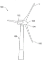
FIG. 1: the wind turbine is installed.
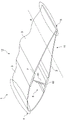
FIG. 2 is a schematic diagram: a simplified perspective view of a cross-section of a wind turbine blade comprising a (meth) acrylic thermoplastic polymer composite and a welding-type interface.
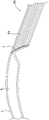
FIG. 3: an enlarged simplified view of a connection region between a (meth) acrylic thermoplastic polymer composite panel comprising a welding-type interface and a reinforcing member.
FIG. 4: flow chart of a preferred embodiment of the manufacturing process of the present invention. The step with the dotted line is optional.
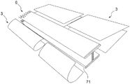
FIG. 5: a simplified diagram of an exploded perspective view of the different components making up a wind turbine blade is described.
[ detailed description of the invention]
In the remainder of the description, a "welding-type interface" corresponds to a welded joint between components, or portions of components. It is meant to be a molten zone, that is to say a zone in which the thermoplastic polymer is said to be liquid during the welding operation. The welding of the present invention may be carried out with or without the provision of a thermoplastic filler material, in particular a (meth) acrylic thermoplastic filler material.
The "I-beam" of the present invention corresponds to a structure having a cross section in the form of I or H. The horizontal elements of the "I" are referred to as flanges, while the vertical elements are referred to as webs. The i-beam of the present invention is preferably formed from a thermoplastic polymer composite.
For the purposes of the present invention, the term "resistance wire" is intended to encompass a resistivity greater than 1X 10 at 20 ℃ C-2Omega mm/m, for example filaments of material larger than 0.1 omega mm/m at 20 ℃. The resistance wire may for example comprise a metal or metal alloy or any other organic conductive element based on carbon, such as a conductive polymer film or wire based on carbon black, carbon nanotubes, graphene. Preferably, the resistance wire has a high melting point, greater than the softening point or pour point (e.g. glass transition temperature) of the (meth) acrylic thermoplastic polymer of the present invention. The melting point of the resistance wire is preferably greater than 300 deg.C, more preferably greater than 500 deg.C, for example greater than 750 deg.C. In the case of the conductive polymer film or wire, it must have a pour point at least equal to that of the (meth) acrylic thermoplastic polymer.
For the purposes of the present invention, the expression "polymer composite" denotes a multicomponent material comprising at least two immiscible components, at least one of which is a polymer, the other component possibly being, for example, a fibrous reinforcing material.
For purposes of the present invention, "fibrous reinforcement" or "fibrous substrate" refers to a plurality of fibers, unidirectional rovings or continuous filament mats, fabrics, felts or non-woven fabrics, which may be in the form of tapes, webs, ribbons, strands or parts.
By "matrix" is meant a material that acts as a binder, which is capable of transferring forces to the fibrous reinforcement material. The "polymer matrix" comprises a polymer, but may also comprise other compounds or materials. Thus, the "(meth) acrylic polymer matrix" refers to any type of compound, polymer, oligomer, copolymer, or block copolymer of acrylic and methacrylic. However, it would not depart from the scope of the invention if the (meth) acrylic polymeric matrix contained up to 10% by weight, preferably less than 5% by weight, of other non-acrylic monomers selected, for example, from: butadiene, isoprene, styrene, substituted styrenes such as alpha-methyl styrene or tert-butyl styrene, cyclosiloxanes, vinyl naphthalene and vinyl pyridine.
"Polymer" refers to a copolymer or a homopolymer. "copolymer" refers to a polymer of several different monomer units combined together, and "homopolymer" refers to a polymer of the same monomer units combined together. "Block copolymer" refers to a polymer comprising one or more uninterrupted sequences of each individual polymer entity, which polymer sequences are chemically different from each other and are bonded to each other by covalent bonds. These polymer sequences are also referred to as polymer blocks.
For the purposes of the present invention, the term "free radical initiator" refers to a compound which can initiate the polymerization of one or more monomers.
For the purposes of the present invention, the term "polymerization" refers to the process by which a monomer or a mixture of monomers is converted into a polymer.
For the purposes of the present invention, the term "monomer" refers to a molecule which can be polymerized.
For the purposes of the present invention, a "thermoplastic polymer" is a polymer which is generally solid at room temperature, crystalline, semi-crystalline or amorphous, which softens during the course of increasing the temperature, in particular after reaching its glass transition temperature (Tg), flows at higher temperatures and can exhibit a marked melting at the point of reaching its "melting point" (Tm) (when it is semi-crystalline) and become solid again during the course of decreasing the temperature below its melting point and below its glass transition temperature. This also applies to thermoplastic polymers that are slightly crosslinked by the presence of polyfunctional monomers or oligomers in the formulation of a (meth) acrylate "syrup" in a weight ratio of preferably less than 10%, preferably less than 5% and more preferably less than 2%, which can be thermoformed when heated above the softening point.
For the purposes of the present invention, "thermosetting polymer" means a plastic material which is irreversibly converted into an insoluble polymer network by polymerization.
"(meth) acrylic monomer" refers to any type of acrylic and methacrylic monomer.
The "(meth) acrylic polymer" means a polymer substantially comprising a (meth) acrylic monomer constituting at least 50% by weight or more of the (meth) acrylic polymer.
For the purposes of the present invention, the term "PMMA" denotes homopolymers and copolymers of Methyl Methacrylate (MMA), the weight ratio of MMA in PMMA preferably being at least 70% by weight for the MMA copolymer.
In the remainder of the description, the same reference numerals are used to indicate the same elements.
According to a first aspect, the invention relates to a wind turbine blade, the structure of which comprises a thermoplastic polymer composite comprising a fibrous reinforcement and a (meth) acrylic thermoplastic polymer matrix.
The (meth) acrylic thermoplastic polymer constituting part of the matrix of the infiltrated fibrous reinforcement may be selected from acrylic polymers and copolymers, such as polyacrylates. They are more particularly chosen from polymethyl methacrylate (PMMA) or derivatives thereof or copolymers of Methyl Methacrylate (MMA), or mixtures thereof.
Preferably, the (meth) acrylic thermoplastic polymer constituting the (meth) acrylic thermoplastic polymer matrix has a glass transition temperature (Tg) of 50 ℃ to 160 ℃, preferably 70 ℃ to 140 ℃ and even more preferably 90 ℃ to 120 ℃. This aspect gives it advantages over other thermoplastic polymers such as polyamines. In fact, polyamines generally have very high melting points, i.e., 200 ℃ to higher, which is not as advantageous for field assembly as the process of the present invention. The glass transition temperature or melting point can be measured by methods known to those skilled in the art. Preferably, these temperatures are measured by differential scanning calorimetry according to the conditions specified in standard ISO 11357-2/2013 for Tg and ISO 11357-3/2011 for Tm. Furthermore, the (meth) acrylic thermoplastic polymer or a part of the (meth) acrylic thermoplastic polymer has a Melt Flow Index (MFI) according to ISO 1133 (230 ℃/3.8 kg) of less than 20 g/10 min. Preferably, the melt flow index is less than 18 g/10 min, more preferably less than 16 g/10 min, advantageously less than 13 g/10 min.
Furthermore, preferably, the inventive wind turbine blade does not comprise more than 50 wt.%, more preferably not more than 40 wt.%, more preferably not more than 30 wt.%, advantageously not more than 20 wt.%, more advantageously not more than 15 wt.% and even more advantageously not more than 10 wt.% of a thermosetting polymer such as an epoxy or polyester or polyurethane resin. Heretofore, thermoset polymers have been commonly used in the manufacture of polymer composite materials for forming wind turbine blades or wind turbine blade components. Also, preferably, the inventive wind turbine blade does not comprise more than 10 wt. -%, more preferably not more than 9 wt. -% and even more preferably not more than 8 wt. -%, advantageously not more than 7 wt. -%, more advantageously not more than 6 wt. -% and even more advantageously not more than 5 wt. -% of a binder, preferably a thermosetting binder. Indeed, adhesive bonding of different wind turbine blade components is typically performed with a thermosetting structural adhesive of the epoxy type.
In the context of the present invention, the use of thermoplastic polymer composite sheets comprising a fibrous reinforcement and a (meth) acrylic thermoplastic polymer matrix enables to significantly reduce the amount of thermosetting polymer used in wind turbine blades and opens up the possibility that sheets for thermosetting polymer composites have not been considered yet, such as the recycling of most blades and convenient field installation or repair.
As will be described in detail below, the (meth) acrylic thermoplastic polymer matrix may be obtained from the polymerization of a liquid (meth) acrylic composition comprising a (meth) acrylic monomer or a mixture of (meth) acrylic monomers, a precursor (meth) acrylic polymer, and at least one free radical initiator.
The (meth) acrylic thermoplastic polymer matrix is composed of a (meth) acrylic thermoplastic polymer, but may further comprise one or more additives and/or one or more fillers.
The carbonaceous filler may in particular be activated carbon, natural anthracite, synthetic anthracite, carbon black, natural graphite, synthetic graphite, carbonaceous nanofillers or mixtures thereof. They are preferably selected from carbonaceous nanofillers, in particular graphene and/or carbon nanotubes and/or carbon nanofibrils or mixtures thereof. These fillers are capable of conducting electricity and heat and thus are capable of improving the lubrication of the polymer matrix when heated. They can then shorten cycle times or facilitate assembly, adjustment or maintenance at the installation site.
The mineral filler comprises in particular a metal hydroxide, more particularly alumina trihydrate (Al (OH)3) Or in the form of magnesium hydroxide (mg (oh)) or magnesium oxide (MgO), calcium hydroxide and mineral fillers such as calcium carbonate, titanium dioxide or silicon dioxide or mineral nanofillers such as nano-titanium dioxide or nano-silicon dioxide.
As additives, organic additives such as impact strength modifiers or block copolymers, heat stabilizers, UV stabilizers, lubricants, viscosity modifiers, pH adjusters (sodium hydroxide), particle size adjusters (sodium sulfate), biocides and mixtures thereof may be mentioned. These additives are capable of improving, in particular, the rheological, chemical and adhesion properties of the (meth) acrylic thermoplastic polymer matrix.
The weight percentage of all additives and fillers with respect to the total weight of the (meth) acrylic thermoplastic polymer matrix is preferably less than 30%, preferably less than 10%.
Fibrous reinforcement generally refers to a plurality of fibers, unidirectional rovings or continuous filament mats, fabrics, felts or non-woven fabrics, which may be in the form of strips, webs, braids, strands or parts.
The fibrous reinforcement comprises one or more fibres, typically an assembly of several fibres, which may have different forms and dimensions; one, two or three dimensional. The one-dimensional form corresponds to linear long fibers. The fibers may be discontinuous or continuous. The fibers may be arranged randomly or parallel to each other in the form of continuous filaments. The two-dimensional form corresponds to a non-woven reinforcement or fiber mat or woven roving or fiber bundle, which may also be braided. Even if the two-dimensional form has a certain thickness and is therefore three-dimensional in principle, it is considered two-dimensional according to the invention. Three-dimensional form for example corresponding to a stack or folded non-woven reinforcement or fiber mat or woven roving or fiber bundle, or a mixture thereof; an assembly of two-dimensional forms in three dimensions.
The fibers may be discontinuous or continuous. When the fibers are continuous, the assembly thereof forms a fabric. Preferably, the fibrous reinforcement is based on continuous fibers. A fiber is defined by its aspect ratio, which is the ratio between the length and the diameter of the fiber. The fibers used in the present invention are long fibers obtained from continuous fibers, or continuous fibers. The fibers have an aspect ratio of at least 1000, preferably at least 1500, more preferably at least 2000, advantageously at least 3000 and more advantageously at least 5000, even more advantageously at least 6000, even more advantageously at least 7500 and most advantageously at least 10000. The continuous fibers have an aspect ratio of at least 1000. The size of the fibers can be measured by methods known to those skilled in the art. Preferably, these dimensions are measured by microscopy according to standard ISO 137.
The source of the fibers making up the fibrous reinforcement may be natural or synthetic. Natural materials which may be mentioned include vegetable fibres, wood fibres, animal fibres or mineral fibres. Plant fibers are, for example, sisal, jute, hemp, flax, cotton, coconut and banana fibers. Animal fibres are for example wool or fur. The mineral fibres may also be selected from glass fibres (in particular of type E, R or S2), basalt fibres, carbon fibres, boron fibres or silica fibres.
Synthetic materials which may be mentioned include polymer fibers selected from thermosetting polymer fibers, thermoplastic polymers or mixtures thereof. The polymer fibers may be comprised of polyamides (aliphatic or aromatic), polyesters, polyvinyl alcohol, polyolefins, polyurethanes, polyvinyl chloride, polyethylene, unsaturated polyesters, epoxies, and vinyl esters.
Preferably, the fibrous reinforcement of the present invention comprises plant fibers, wood fibers, animal fibers, mineral fibers, synthetic polymer fibers, glass fibers, basalt fibers and carbon fibers, alone or in a mixture. More preferably, the fibrous reinforcement of the present invention comprises carbon fibers or glass fibers. More preferably, the fibrous reinforcement of the present invention consists essentially of carbon fibers or glass fibers.
The fibers of the fibrous reinforcement material have a diameter of, for example, 0.005 to 100 μm, preferably 1 to 50 μm, more preferably 5 to 30 μm and advantageously 10 to 25 μm.
Preferably, the fibers of the fibrous reinforcement of the invention are selected from continuous fibers for the one-dimensional form of the fibrous reinforcement or from long fibers or continuous fibers for the two-dimensional or three-dimensional form of the fibrous reinforcement.
Fig. 1 shows a conventional wind turbine 100 with a horizontal axis comprising a mast 101, a nacelle 102 and a rotor with a substantially horizontal rotor axis. The rotor comprises a hub 103 and three wind turbine blades 1 extending radially from the hub 103, each having a root 104 of the wind turbine blade closest to the hub 103 and a tip 105 of the wind turbine blade furthest from the hub 103. The rotor is driven by wind energy; it is connected, directly or indirectly (via a geared speed multiplier) to a mechanical system that will utilize the collected energy (pump, generator, etc.).
As can be seen in fig. 1, the wind turbine blade 1 typically has a cross-sectional shape that changes between the tip 105 and the root 104 of the wind turbine blade, corresponding to the connection region. The wind turbine blade 1 comprises a shell defining a lower surface 11 and an upper surface 12 as well as a leading edge 4 and a trailing edge 5. The shell (at least partially defining the outer surface of the wind turbine blade 1) is at least partially formed from a sheet 3 of thermoplastic polymer composite material. The outer shell is formed, for example, more particularly, from a sheet 3 of thermoplastic polymer composite material joined to a reinforcing member 6. Alternatively, the reinforcing member 6 may be completely surrounded by the sheet 3 of thermoplastic polymer composite material and thus not participate in forming the outer shell.
The sheet 3 of thermoplastic polymer composite material may take various forms such as a strip, a sheet, a plate or, more generally, a rigid polymer composite part.
The sheet 3 of thermoplastic polymer composite material may be further subjected to subsequent treatments aimed at reinforcing the outer shell and improving its mechanical and chemical properties. The treatment may for example be particularly located on certain areas of the outer surface of the wind turbine blade 1, such as along the leading edge 4. In this case, the treatment may comprise the deposition of a protective layer of plastic or metal covering the leading edge 4.
As shown in fig. 2, the wind turbine blade 1 further comprises at least one longitudinal stiffening member 6 made of a thermoplastic polymer composite inside said wind turbine blade 1, extending along the longitudinal axis a of the wind turbine blade. The reinforcement member 6 is disposed between at least one sheet of material defining the leading edge 4 and at least one sheet of material defining the trailing edge 5.
As shown in fig. 2, the inventive wind turbine blade may have a leading edge formed from a single monolithic piece welded to the stiffening member 6. Indeed, the present invention, based at least in part on the use of a thermoplastic polymer composite comprising a fibrous reinforcement and a (meth) acrylic thermoplastic polymer matrix, is able to produce a novel wind turbine blade design in the form of a leading edge having a form formed from a single monolithic part welded to a stiffening member 6 as shown in fig. 2 and in the method of assembly as will be detailed below.
The sheet element 3 and the stiffening member are connected to form together at least a part of the outer shell of the wind turbine blade.
The reinforcement member 6 provides improved stability and local stiffness compared to the thermoplastic polymer composite sheet material alone. The stiffening member 6 extends inside said wind turbine blade 1 along the longitudinal axis a of the wind turbine blade to stabilize its structure. Preferably, the reinforcing member 6 comprises a thermoplastic polymer composite comprising a fibrous reinforcement and a (meth) acrylic thermoplastic polymer matrix.
As shown in fig. 2, the reinforcing member 6 has the form of an "i" beam comprising a web 51 and two flanges 62 connected to each other by a web 61. The web may be formed from an assembly comprising a thermoplastic polymer composite encapsulating a low density structure. This arrangement forms a sandwich-type structure in which the low-density structure is surrounded by one or more sheets of thermoplastic polymer composite material. Alternatively, the reinforcing member 6 may take the form of a tube having a quadrangular shape (preferably square or rectangular) in cross section, which may thus correspond to a reinforcing member comprising two webs and two flanges.
As shown in fig. 3, the flanges 62 may be formed from a stack of strips 63 of thermoplastic polymer composite material comprising a fibrous reinforcement material and a (meth) acrylic thermoplastic polymer matrix. Preferably, the flange 62 is connected to the web 61 by a welding-type interface 7. Alternatively, the flange 62 may be attached to the web 61 by an epoxy or polyester or polyurethane adhesive.
Fig. 3 depicts an enlarged view of a weld-type interface 7 connecting a sheet of thermoplastic polymer composite material to a strength member 6.
The welding-type interface 7 has a thickness greater than or equal to 0.5 mm, preferably greater than or equal to 1 mm, more preferably greater than or equal to 2 mm.
The thickness of the welding-type interface 7 can be measured by conventional methods, for example, from the perpendicular interface of the welding-type interface 7.
When the welding-type interface 7 is capable of connecting a sheet of thermoplastic polymer composite material to the stiffening member 6, it extends along the longitudinal axis a of the wind turbine blade. Fig. 3 depicts only a cross-sectional view of the welding-type interface 7, but the latter preferably extends over the entire length of the reinforcement member. Thus, the welding-type interface may have a length greater than 5 meters, preferably greater than 10 meters, and even more preferably greater than 20 meters.
In the description of fig. 3, it is also possible to understand that there is a low-density structure 8 between two sheets 3 of thermoplastic polymer composite. In fact, preferably, the sheet 3 of thermoplastic polymer composite material at least partially constituting the outer shell encapsulates the low-density structure 8. This arrangement forms a sandwich-type structure in which the low-density structure 8 is surrounded by one or more sheets 3 of thermoplastic polymer composite material. The low density structure typically has a density of less than 200 kg/m, preferably less than 150 kg/m and even more preferably less than 75 kg/m. The low-density structure is for example selected from wood (such as balsa), honeycomb or expanded or foamed plastic (such as expanded polystyrene or PET (polyethylene terephthalate) foam, or PVC (polyvinyl chloride) foam).
According to another aspect, the invention relates to a wind turbine blade component 2 made of a thermoplastic polymer composite material for forming the wind turbine blade 1 of the invention, wherein the thermoplastic polymer composite material comprises a fibrous reinforcement material and a (meth) acrylic thermoplastic polymer matrix.
Preferably, the thermoplastic polymer composite of the wind turbine blade component 2 is at least covered with a (meth) acrylic thermoplastic polymer layer at least 1 mm, preferably at least 2 mm, more preferably at least 3 mm thick, for example on the surface intended to be welded. The thermoplastic polymer composite is more particularly covered with a layer of (meth) acrylic thermoplastic polymer at the assembly interface area intended to form the future weld-type interface. This makes it possible in particular to avoid regions with a lower concentration of thermoplastic polymer. Alternatively, the wind turbine blade component 2 may have at least one face covered with a layer of a (meth) acrylic thermoplastic polymer.
According to another aspect and as shown in fig. 5, the present invention relates to a method of manufacturing a wind turbine blade 1 of the present invention from at least two wind turbine blade parts made of a thermoplastic polymer composite material comprising a fibrous reinforcement material and a (meth) acrylic thermoplastic polymer matrix, said method comprising the steps of:
-arranging 220 two wind turbine blade parts made of thermoplastic polymer composite material adjacently or overlappingly at an assembly interface 71,
-heating 230 at the assembly interface 71 to melt the (meth) acrylic thermoplastic polymer matrix, and
-applying 240 pressure at the interface in order to weld together the at least two wind turbine blade parts made of thermoplastic polymer composite material, thereby forming a welded interface 7.
The (meth) acrylic thermoplastic polymer matrix may be melted by a technique selected from the group consisting of: ultrasonic welding, induction welding, resistance wire welding, friction stir welding, laser welding, heating by infrared or ultraviolet radiation. Preferably by resistance wire welding. The welding of the present invention may be performed with or without the provision of a (meth) acrylic thermoplastic filler material.
Preferably, the temperature at the assembly interface 71 during the heating step 230 is 160 to 300 ℃. This temperature can be measured conventionally by an infrared thermometer.
Furthermore, the method 200 for manufacturing a wind turbine blade of the present invention may comprise a prior step 210 of manufacturing a wind turbine blade component made of a thermoplastic polymer composite comprising a fibrous reinforcement material and a (meth) acrylic thermoplastic polymer matrix.
Step 210 of manufacturing a wind turbine blade component the method comprises the sub-steps of:
impregnating 211 the fibrous reinforcement with a liquid (meth) acrylic composition,
-polymerizing 212 the liquid (meth) acrylic composition impregnating the fibrous reinforcement.
One of the advantages of the present invention is that a wind turbine blade component 2 made of a thermoplastic polymer composite material may be manufactured at a temperature of less than 150 ℃, preferably less than 140 ℃, even more preferably less than 125 ℃, advantageously less than 120 ℃, more advantageously less than 110 ℃ and even more advantageously less than 100 ℃. For example, the step of impregnating the fibrous reinforcing material with the liquid (meth) acrylic composition is carried out at a temperature of less than 150 ℃, preferably less than 120 ℃, even more preferably less than 100 ℃ or less than 80 ℃. In fact, the liquid (meth) acrylic composition used for manufacturing the wind turbine blade component 2 made of the thermoplastic polymer composite is liquid at temperatures well below the conventional melting point of conventional thermoplastics. This thereby enables the production of very large sized wind turbine blade components without the need to carry out a process of heating the components to high temperatures. Thus, it should be understood that the processes that can be used to manufacture these parts do not require the step of heating at elevated temperatures as is the case with conventional thermoplastics.
The step 210 of manufacturing the wind turbine blade component 2 may further comprise a sub-step 213 of depositing a layer of a (meth) acrylic thermoplastic polymer. Such deposition may be preferred at assembly interface areas intended to form future weld-type interfaces. Alternatively, the deposition is performed over the entire wind turbine blade component 2.
With respect to step 210 of manufacturing wind turbine blade components, different methods may be employed to manufacture these components. Vacuum Assisted Resin Infusion (VARI), pultrusion, vacuum infusion molding, pressurized infusion molding, autoclave molding, Resin Transfer Molding (RTM) and variants thereof (e.g. HP-RTM, C-RTM, I-RTM), Reaction Injection Molding (RIM), enhanced reaction injection molding (R-RIM) and variants thereof, punch molding, compression molding, Liquid Compression Molding (LCM) or Sheet Molding (SMC) or Bulk Molding (BMC) may be mentioned. Preferably, the wind turbine blade component made of the polymer composite is manufactured by low pressure injection moulding, infusion moulding or by moulding a strip of (meth) acrylic thermoplastic polymer composite, such as a pre-impregnated strip.
A first preferred manufacturing method of manufacturing a wind turbine blade component is a method of transferring a liquid (meth) acrylic composition onto the fibre-reinforced material by impregnating the fibre-reinforced material in a mould. Methods requiring a mold are listed above and include the term molding.
A second preferred manufacturing method of manufacturing a wind turbine blade component is a method of using the liquid composition in a pultrusion process. The fiber is guided through a resin bath containing the composition of the invention (the original batch is suspected of being a mistake of the batch). The fibers in the form of a fibrous reinforcement are for example in the form of unidirectional rovings or continuous filament mats. After immersion in the resin bath, the wet fibers are drawn through a heated die where polymerization occurs.
A third preferred manufacturing method is Vacuum Assisted Resin Infusion (VARI).
The method of manufacturing a wind turbine blade component as well as a mechanical or structural component or product may further comprise a post-forming step. Post-forming includes bending and modifying the shape of the composite part. The method of manufacturing a wind turbine blade component may further comprise a rolling step.
The thermoplastic parts obtained by the process of the invention may be post-formed after polymerization of the liquid composition of the invention. Forming includes bending and modifying the shape of the composite part.
As for the liquid (meth) acrylic composition, it may contain a (meth) acrylic monomer, a precursor (meth) acrylic polymer, and a radical initiator as described in WO 2013/056845 and WO 2014/013028.
Furthermore, during the impregnation process, the viscosity of the liquid (meth) acrylic composition or the impregnation slurry must be adjusted and adjusted so as not to be too fluid or too viscous in order to correctly impregnate each fiber of the fibrous reinforcement material when preparing the polymer composite. When partially wetted due to too high fluidity or too high viscosity of the slurry, "bare" areas (i.e., unimpregnated areas) and areas where polymer droplets are formed on the fibers, respectively, occur, which is the cause of bubble formation. These "bare" areas and these air bubbles lead to defects in the final composite material, which are responsible, among other things, for the reduction of the mechanical strength of the final composite material. Further, in the case of use without impregnation, it is desirable to have a liquid composition that polymerizes rapidly with good conversion in order to increase productivity.
Thus, the dynamic viscosity of the liquid (meth) acrylic composition at 25 ℃ is preferably from 10 to 10000 mPa s. The liquid compositionOr the (meth) acrylic syrup has a dynamic viscosity of from 10 to 10000 mPas, preferably from 20 to 7000 mPas and advantageously from 20 to 5000 mPas. The viscosity of the liquid (meth) acrylic composition or the liquid (meth) acrylic syrup can be easily measured with a rheometer or a viscometer. The dynamic viscosity was measured at 25 ℃. If the liquid (meth) acrylic syrup exhibits Newtonian behavior, i.e., no shear thinning occurs, the dynamic viscosity is independent of the shear in the rheometer or the velocity of the viscometer's center shaft. If the liquid composition exhibits non-Newtonian behaviour, i.e. shear thinning occurs, the dynamic viscosity is 1 s at 25 DEG C-1Shear rate measurement of (2).
As the (meth) acrylic monomer, the monomer is selected from the group consisting of acrylic acid, methacrylic acid, alkyl acrylic monomers, alkyl methacrylic monomers, hydroxyalkyl acrylic monomers, and hydroxyalkyl methacrylic monomers, and mixtures thereof.
Preferably, the (meth) acrylic monomer is selected from acrylic acid, methacrylic acid, hydroxyalkyl acrylic monomers, hydroxyalkyl methacrylic monomers, alkyl acrylic monomers, alkyl methacrylic monomers and mixtures thereof, the alkyl group containing from 1 to 22 linear, branched or cyclic carbons; the alkyl group preferably contains 1 to 12 straight, branched or cyclic carbons.
Advantageously, the (meth) acrylic monomer is chosen from methyl methacrylate, ethyl methacrylate, methyl acrylate, ethyl acrylate, methacrylic acid, acrylic acid, n-butyl acrylate, isobutyl acrylate, n-butyl methacrylate, isobutyl methacrylate, cyclohexyl acrylate, cyclohexyl methacrylate, isobornyl acrylate, isobornyl methacrylate, hydroxyethyl acrylate and hydroxyethyl methacrylate, and mixtures thereof.
According to a preferred embodiment, at least 50% by weight and preferably at least 60% by weight of the (meth) acrylic monomer is methyl methacrylate.
According to a first more preferred embodiment, at least 50% by weight, preferably at least 60% by weight, more preferably at least 70% by weight, advantageously at least 80% by weight and even more advantageously 90% by weight of the monomer is a mixture of methyl methacrylate, optionally with at least one other monomer.
As the precursor (meth) acrylic polymer, mention may be made of polyalkyl methacrylate or polyalkyl acrylate. According to a preferred embodiment, the precursor (meth) acrylic polymer is poly (methyl methacrylate) (PMMA).
According to one embodiment, the Methyl Methacrylate (MMA) homopolymer or copolymer comprises at least 70%, preferably at least 80%, advantageously at least 90% and more advantageously at least 95% by weight of methyl methacrylate.
According to another embodiment, the PMMA is a mixture of at least one homopolymer and at least one copolymer of MMA, or a mixture of at least two homopolymers or two copolymers of MMA having different average molecular weights, or a mixture of at least two copolymers of MMA having different monomer compositions.
Copolymers of Methyl Methacrylate (MMA) comprise 70 to 99.7 wt.% methyl methacrylate and 0.3 to 30 wt.% of at least one monomer containing at least one ethylenic unsaturation copolymerizable with the methyl methacrylate.
These monomers are well known and mention may be made in particular of acrylic acid and methacrylic acid and of alkyl (meth) acrylates in which the alkyl group contains from 1 to 12 carbon atoms. Mention may be made, for example, of methyl acrylate and ethyl, butyl or 2-ethylhexyl (meth) acrylate. Preferably, the comonomer is an alkyl acrylate, wherein the alkyl group contains 1 to 4 carbon atoms.
According to a first preferred embodiment, the copolymer of Methyl Methacrylate (MMA) comprises from 80% to 99.7% by weight, advantageously from 90% to 99.7% by weight and more advantageously from 90% to 99.5% by weight of methyl methacrylate and from 0.3% to 20% by weight, advantageously from 0.3% to 10% by weight and more advantageously from 0.5% to 10% by weight of at least one monomer containing at least one ethylenic unsaturation copolymerizable with the methyl methacrylate. Preferably, the comonomer is selected from methyl acrylate and ethyl acrylate and mixtures thereof.
The weight average molecular weight of the precursor (meth) acrylic polymer should be relatively high, meaning more than 50000 g/mol, preferably more than 100000 g/mol. The weight average molecular weight can be determined by size exclusion chromatography.
The precursor (meth) acrylic polymer is completely soluble in the (meth) acrylic monomer or in a mixture of (meth) acrylic monomers. This can increase the viscosity of the (meth) acrylic monomer or the mixture of (meth) acrylic monomers. The resulting liquid composition or solution is commonly referred to as a "slurry" or "prepolymer". The liquid (meth) acrylic syrup has a dynamic viscosity value of 10 to 10000 mPa.s. The viscosity of the slurry can be easily measured with a rheometer or viscometer. The dynamic viscosity was measured at 25 ℃. Advantageously, the liquid (meth) acrylic syrup is free of intentionally added additional solvent.
The (meth) acrylic monomer or mixture of (meth) acrylic monomers in the liquid (meth) acrylic composition or the liquid (meth) acrylic syrup is present in an amount of at least 40 wt%, preferably at least 45 wt%, more preferably at least 50 wt%, advantageously at least 60 wt% and more advantageously at least 65 wt% in the liquid (meth) acrylic composition.
The precursor (meth) acrylic polymer in the liquid (meth) acrylic composition or the liquid (meth) acrylic syrup is present in an amount of at least 10 wt%, preferably at least 15 wt%, advantageously at least 18 wt% and more advantageously at least 20 wt% in the liquid (meth) acrylic composition.
The precursor (meth) acrylic polymer in the liquid (meth) acrylic composition or the liquid (meth) acrylic syrup is present in an amount of at most 60 wt%, preferably at most 50 wt%, advantageously at most 40 wt% and more advantageously at most 35 wt% in the liquid (meth) acrylic composition.
The liquid (meth) acrylic composition or the slurry, the slurry compound being mixed in the following weight percentages:
the (meth) acrylic monomer in the liquid composition or the (meth) acrylic syrup is present in a proportion of 40 to 90% by weight and preferably 45 to 85% by weight of the composition composed of the (meth) acrylic monomer and the (meth) acrylic polymer,
the (meth) acrylic polymer in the liquid composition or in the (meth) acrylic syrup is present in a proportion of from 10% to 60% by weight and advantageously from 15% to 55% by weight of the composition consisting of (meth) acrylic monomer and (meth) acrylic polymer; preferably, the (meth) acrylic polymer in the liquid composition is present in a proportion of 18 to 30 wt%, more preferably 20 to 25 wt% of the composition consisting of the (meth) acrylic monomer and the (meth) acrylic polymer.
As the radical initiator, there may be mentioned preferably a water-soluble radical polymerization initiator or a fat-soluble or partially fat-soluble radical polymerization initiator.
Water-soluble free-radical polymerization initiators, in particular sodium, potassium or ammonium peroxodisulfate, are used alone or in the presence of reducing agents such as sodium metabisulfite or sodium dithionite, sodium thiosulfate, sodium formaldehyde sulfoxylate, 2-hydroxy-2-sulfinatoacetic acid, mixtures of sodium sulfite and the disodium salt of 2-hydroxy-2-sulfoacetic acid, or mixtures of the disodium salt of hydroxysulfinatoacetic acid and the disodium salt of hydroxysulfoacetic acid.
Fat-soluble or partially fat-soluble free-radical polymerization initiators are, in particular, peroxides or hydroperoxides and derivatives of azobisisobutyronitrile. Peroxides or hydroperoxides are used in combination with the reducing agents described above to lower their activation temperature.
The weight percentage of the initiator relative to the total weight of the monomer mixture is preferably from 0.05 to 3% by weight, preferably from 0.1 to 2% by weight.
As shown in fig. 5, a wind turbine blade 1 of the present invention may comprise a plurality of parts 2 made of a thermoplastic polymer composite, wherein the thermoplastic polymer composite comprises a fibrous reinforcement and a (meth) acrylic thermoplastic polymer matrix, and wherein said wind turbine blade parts 2 have an assembly interface region 71 enabling their welding to a reinforcement member 6 quickly and easily.
The invention thus provides a wind turbine blade that can be manufactured faster than conventional wind turbine blades, while being recyclable and satisfactory in terms of mechanical and chemical stability. The invention may also be easily and quickly assembled, repaired or adjusted at the installation site.
All these advantages thus contribute to reducing the production and installation costs of such wind turbines.
Claims (37)
1. Wind turbine blade (1), the wind turbine blade (1) comprising an outer shell formed at least in part from sheets (3) of a thermoplastic polymer composite material, the outer shell defining a leading edge (4) and a trailing edge (5) of the wind turbine blade formed from a single monolithic part, and at least one stiffening member (6) made from a polymer composite material, the stiffening member (6) extending inside the wind turbine blade (1) along a longitudinal axis (a) of the wind turbine blade, the stiffening member (6) being arranged between at least one sheet defining the leading edge (4) and at least one sheet defining the trailing edge (5), characterized in that the thermoplastic polymer composite material comprises a fibrous reinforcement and a (meth) acrylic thermoplastic polymer matrix, and in that at least one sheet (3) of thermoplastic polymer composite material is connected to the trailing edge (5) by a welding type interface (7) A stiffening member (6), wherein the wind turbine blade does not comprise more than 10 wt% of a thermosetting adhesive.
2. A wind turbine blade as claimed in claim 1, wherein the fibre reinforcement material is based on fibres having an aspect ratio of at least 1000.
3. A wind turbine blade as claimed in claim 1 or 2, characterized in that it does not comprise more than 50% by weight of a thermosetting polymer.
4. A wind turbine blade as claimed in claim 1 or 2, characterized in that it does not comprise more than 15% by weight of a thermosetting polymer.
5. A wind turbine blade as claimed in claim 1 or 2, characterized in that it does not comprise more than 8% by weight of a thermosetting binder.
6. A wind turbine blade as claimed in claim 1 or 2, characterized in that it does not comprise more than 6% by weight of a thermosetting binder.
7. A wind turbine blade as claimed in claim 1 or 2, characterized in that the (meth) acrylic thermoplastic polymer is selected from polymethyl methacrylate or a copolymer of methyl methacrylate or a mixture thereof.
8. A wind turbine blade as claimed in claim 1 or 2, characterised in that the fibre reinforcement material comprises fibres selected from carbon fibres, glass fibres, basalt fibres or polymer-based fibres, or plant fibres, alone or in a mixture.
9. A wind turbine blade as claimed in claim 1 or 2, characterized in that the thermoplastic polymer matrix further comprises one or more additives or fillers.
10. A wind turbine blade as claimed in claim 1 or 2, characterized in that the (meth) acrylic thermoplastic polymer has a glass transition temperature of 50 ℃ to 160 ℃.
11. A wind turbine blade as claimed in claim 1 or 2, characterized in that the stiffening member (6) has the form of an "i" beam comprising a web (61) and two flanges (62) connected to each other by the web (61).
12. A wind turbine blade as claimed in claim 11, characterized in that the flanges (62) are formed by stacking strips (63) of thermoplastic polymer composite material or by low pressure injection or infusion moulded composite parts.
13. A wind turbine blade as claimed in claim 11, characterized in that the flange (62) is connected to the web (61) by a welding type interface (7).
14. Wind turbine blade as claimed in claim 11, wherein said flange (62) is connected to the web (61) by means of an epoxy or polyester or polyurethane adhesive.
15. A wind turbine blade as claimed in claim 1 or 2, characterized in that the welded interface (7) has a thickness greater than or equal to 0.5 mm.
16. A wind turbine blade as claimed in claim 1 or 2, characterized in that the leading edge is formed by a single one-piece part welded to the stiffening member (6).
17. Wind turbine blade as claimed in claim 1 or 2, characterized in that the sheet (3) of thermoplastic polymer composite material constituting the outer shell encapsulates the low density structure (8).
18. Wind turbine blade as claimed in claim 1 or 2, characterized in that it comprises at least one resistance wire at the welding-type interface (7).
19. A wind turbine blade as claimed in claim 1 or 2, wherein the welded interface has a length of more than 5 metres.
20. A wind turbine blade as claimed in claim 1 or 2, characterized in that the welding-type interface (7) extends along a longitudinal axis (a) of the wind turbine blade.
21. A wind turbine blade as claimed in claim 12, characterized in that the flanges (62) are formed by a stack of strips (63) of pre-impregnated thermoplastic polymer composite material or by a low pressure injection or infusion moulded composite part.
22. Wind turbine blade as claimed in claim 17, characterized in that the low-density structure (8) is constituted by a material selected from wood, honeycomb or expanded plastic.
23. A wind turbine blade component (2) made of a thermoplastic polymer composite material for forming a wind turbine blade (1) as claimed in any of the preceding claims, characterized in that the thermoplastic polymer composite material comprises a fibrous reinforcement material and a (meth) acrylic thermoplastic polymer matrix.
24. A wind turbine blade component (2) made of a thermoplastic polymer composite as claimed in claim 23, characterized in that the thermoplastic polymer composite is at least partially covered with a (meth) acrylic thermoplastic polymer layer at least 1 mm thick.
25. A method (200) of manufacturing a wind turbine blade (1) as claimed in any of claims 1 to 22 from at least two wind turbine blade parts made of a thermoplastic polymer composite comprising a fibrous reinforcement and a (meth) acrylic thermoplastic polymer matrix, the method comprising the steps of:
-adjacently or overlappingly arranging (220) at least two wind turbine blade parts (2) made of thermoplastic polymer composite material at an assembly interface (71),
-heating (230) at an assembly interface (71) to melt the (meth) acrylic thermoplastic polymer matrix, and
-applying (240) pressure at the interface in order to weld together the at least two wind turbine blade parts made of thermoplastic polymer composite material, thereby forming a welded interface (7).
26. A method as claimed in claim 25, further comprising a preceding step of manufacturing (210) a wind turbine blade component, comprising the sub-steps of:
-impregnating (211) the fibrous reinforcement with a liquid (meth) acrylic composition,
-polymerizing (212) the liquid (meth) acrylic composition impregnated with the fibrous reinforcement.
27. A process as claimed in claim 26 characterised in that the liquid (meth) acrylic composition comprises a (meth) acrylic monomer, a precursor (meth) acrylic polymer and a free radical initiator.
28. A method as claimed in claim 27 characterised in that the (meth) acrylic monomer in the liquid (meth) acrylic composition is present in an amount of at least 40% by weight of the liquid (meth) acrylic composition.
29. A process as claimed in claim 27, characterised in that the precursor (meth) acrylic polymer in the liquid (meth) acrylic composition is present in an amount of at least 10% by weight of the liquid (meth) acrylic composition.
30. A process as claimed in claim 27, characterised in that the precursor (meth) acrylic polymer in the liquid (meth) acrylic composition is present in an amount of up to 60% by weight of the liquid (meth) acrylic composition.
31. A method as claimed in claim 27, characterised in that the compound is incorporated in the following percentages by weight:
the (meth) acrylic monomer is present in a proportion of 40 to 90% by weight of the composition consisting of the (meth) acrylic monomer and the precursor (meth) acrylic polymer,
the precursor (meth) acrylic polymer is present in a proportion of 10% to 60% by weight of the composition consisting of (meth) acrylic monomer and precursor (meth) acrylic polymer.
32. A method as claimed in any one of claims 25 to 31, characterized in that the wind turbine blade component (2) made of thermoplastic polymer composite material is manufactured by low-pressure injection moulding, infusion moulding or by moulding a strip pre-impregnated with (meth) acrylic thermoplastic polymer composite material.
33. A method as claimed in any one of claims 25 to 31, characterized in that the wind turbine blade component (2) made of the thermoplastic polymer composite is manufactured at a temperature of less than 150 ℃.
34. A method as claimed in any one of claims 25 to 31, characterised in that the thermoplastic polymer matrix is melted (230) by a technique selected from the group consisting of: ultrasonic welding, induction welding, resistance wire welding, friction stir welding, laser welding, heating by infrared or ultraviolet radiation.
35. A method as claimed in claim 33, characterized in that the wind turbine blade component (2) made of the thermoplastic polymer composite is manufactured at a temperature of less than 100 ℃.
36. A method as claimed in claim 34, characterized in that said thermoplastic polymer matrix is melted (230) by a technique selected from the group consisting of: welding by resistance wire.
37. A method as claimed in any one of claims 25 to 31, characterised in that during the heating step (230) the temperature at the assembly interface (71) is 160 to 300 ℃.
Applications Claiming Priority (3)
| Application Number | Priority Date | Filing Date | Title |
|---|---|---|---|
| FR1752045 | 2017-03-13 | ||
| FR1752045A FR3063774B1 (en) | 2017-03-13 | 2017-03-13 | THERMOPLASTIC POLYMER COMPOSITE WIND TURBINE BLADE, PART OF THE BLADE AND MANUFACTURING METHOD |
| PCT/FR2018/050590 WO2018172656A1 (en) | 2017-03-13 | 2018-03-13 | Wind turbine blade made of thermoplastic polymer composite, part of said blade and production method |
Publications (2)
| Publication Number | Publication Date |
|---|---|
| CN110612392A CN110612392A (en) | 2019-12-24 |
| CN110612392B true CN110612392B (en) | 2022-07-12 |
Family
ID=59253639
Family Applications (1)
| Application Number | Title | Priority Date | Filing Date |
|---|---|---|---|
| CN201880031421.7A Active CN110612392B (en) | 2017-03-13 | 2018-03-13 | Wind turbine blade made of thermoplastic polymer composite, component of said blade and manufacturing method |
Country Status (10)
| Country | Link |
|---|---|
| US (1) | US11624347B2 (en) |
| EP (1) | EP3596338A1 (en) |
| JP (1) | JP7158401B2 (en) |
| KR (1) | KR102478910B1 (en) |
| CN (1) | CN110612392B (en) |
| BR (1) | BR112019018836A2 (en) |
| CA (1) | CA3055485A1 (en) |
| FR (1) | FR3063774B1 (en) |
| MX (1) | MX2019010637A (en) |
| WO (1) | WO2018172656A1 (en) |
Families Citing this family (6)
| Publication number | Priority date | Publication date | Assignee | Title |
|---|---|---|---|---|
| CN109153150B (en) * | 2017-03-10 | 2021-04-09 | Gfsi集团有限责任公司 | Wind turbine blade recovery |
| CN114375368A (en) * | 2019-09-13 | 2022-04-19 | 西门子歌美飒可再生能源创新与技术有限公司 | Wind turbine blade |
| GB202015867D0 (en) * | 2020-10-07 | 2020-11-18 | Blade Dynamics Ltd | Blade shell section for a wind turbine blade |
| GB2602444B (en) * | 2020-11-11 | 2023-05-10 | Coeus Ltd | Structural shell |
| KR102513583B1 (en) | 2021-05-04 | 2023-03-22 | 두산에너빌리티 주식회사 | Blade of wind turbine and manufacturing method of the same |
| FR3140573A1 (en) | 2022-10-05 | 2024-04-12 | Arkema France | Spar FOOTBED AND CORRESPONDING PRODUCTION METHOD |
Citations (2)
| Publication number | Priority date | Publication date | Assignee | Title |
|---|---|---|---|---|
| CN102116253A (en) * | 2009-12-30 | 2011-07-06 | 通用电气公司 | Spar for a wind turbine rotor blade and method for fabricating the same |
| CN103998211A (en) * | 2011-10-21 | 2014-08-20 | 阿肯马法国公司 | Composite material via in-situ polymerization of thermoplastic (meth)acrylic resins and its use |
Family Cites Families (18)
| Publication number | Priority date | Publication date | Assignee | Title |
|---|---|---|---|---|
| AUPR673101A0 (en) | 2001-07-31 | 2001-08-23 | Cooperative Research Centre For Advanced Composite Structures Limited | Welding techniques for polymer or polymer composite components |
| EP1393892A1 (en) * | 2002-08-29 | 2004-03-03 | Alcan Technology & Management Ltd. | Foamed plastic plate |
| EP1880833A1 (en) * | 2006-07-19 | 2008-01-23 | National University of Ireland, Galway | Composite articles comprising in-situ-polymerisable thermoplastic material and processes for their construction |
| US7976282B2 (en) * | 2007-01-26 | 2011-07-12 | General Electric Company | Preform spar cap for a wind turbine rotor blade |
| GB2463250A (en) | 2008-09-04 | 2010-03-10 | Vestas Wind Sys As | A wind turbine blade formed from welded thermoplastic sections |
| US8556590B2 (en) * | 2009-12-25 | 2013-10-15 | Mitsubishi Heavy Industries, Ltd. | Wind-turbine rotor blade |
| GB2489477B (en) * | 2011-03-30 | 2013-04-24 | Gurit Uk Ltd | Spar for a turbine blade and manufacture thereof |
| FR2973803B1 (en) * | 2011-04-07 | 2013-04-05 | Arkema France | NEW ACRYLIC MATERIAL REINFORCED WITH SHOCK |
| FR2977186B1 (en) * | 2011-07-01 | 2014-08-22 | Daher Aerospace | METHOD FOR LOCALLY REINFORCING A COMPOSITE FIBROUS REINFORCED PANEL AND PANEL OBTAINED BY SUCH A METHOD |
| US10130509B2 (en) * | 2012-04-12 | 2018-11-20 | Ivan Dmitrievich Zakharov | Drainage device and method of producing same |
| US8641339B2 (en) * | 2012-06-25 | 2014-02-04 | Siemens Aktiengesellschaft | Apparatus for railroad transportation of wind turbine blades |
| FR2993581B1 (en) | 2012-07-18 | 2016-01-22 | Arkema France | IMPREGNATION PROCESS FOR A FIBROUS SUBSTRATE, LIQUID (METH) ACRYLIC SYRUP FOR THE IMPREGNATION PROCESS, ITS POLYMERIZATION PROCESS AND STRUCTURE PRODUCT OBTAINED THEREFROM |
| FR3002940B1 (en) * | 2013-03-08 | 2016-01-22 | Arkema France | LIQUID (METH) ACRYLIC SYRUP FOR IMPREGNATING A FIBROUS SUBSTRATE AND PROCESS FOR PRODUCING THE SAME, METHOD FOR IMPREGNATING A FIBROUS SUBSTRATE, COMPOSITE MATERIAL OBTAINED AFTER POLYMERIZATION OF THE PRE-IMPREGNATED SUBSTRATE |
| US10006436B2 (en) * | 2014-12-18 | 2018-06-26 | General Electric Company | Wind turbine rotor blades with load-transferring exterior panels |
| FR3037066B1 (en) * | 2015-06-05 | 2019-06-21 | Arkema France | PROCESS FOR IMPREGNATING A FIBROUS SUBSTRATE WITH A (METH) ACRYLIC MIXTURE COMPRISING A FLAME RETARDANT SUBSTANCE |
| US10830205B2 (en) * | 2015-08-26 | 2020-11-10 | General Electric Company | Rotor blades having thermoplastic components and methods of assembling same |
| US10422315B2 (en) * | 2015-09-01 | 2019-09-24 | General Electric Company | Pultruded components for a shear web of a wind turbine rotor blade |
| US10161381B2 (en) * | 2015-09-14 | 2018-12-25 | General Electric Company | Rotor blades having thermoplastic components and methods for joining rotor blade components |
-
2017
- 2017-03-13 FR FR1752045A patent/FR3063774B1/en active Active
-
2018
- 2018-03-13 JP JP2019549430A patent/JP7158401B2/en active Active
- 2018-03-13 CN CN201880031421.7A patent/CN110612392B/en active Active
- 2018-03-13 EP EP18714569.3A patent/EP3596338A1/en active Pending
- 2018-03-13 MX MX2019010637A patent/MX2019010637A/en unknown
- 2018-03-13 BR BR112019018836A patent/BR112019018836A2/en unknown
- 2018-03-13 CA CA3055485A patent/CA3055485A1/en active Pending
- 2018-03-13 KR KR1020197029554A patent/KR102478910B1/en active IP Right Grant
- 2018-03-13 US US16/492,958 patent/US11624347B2/en active Active
- 2018-03-13 WO PCT/FR2018/050590 patent/WO2018172656A1/en unknown
Patent Citations (2)
| Publication number | Priority date | Publication date | Assignee | Title |
|---|---|---|---|---|
| CN102116253A (en) * | 2009-12-30 | 2011-07-06 | 通用电气公司 | Spar for a wind turbine rotor blade and method for fabricating the same |
| CN103998211A (en) * | 2011-10-21 | 2014-08-20 | 阿肯马法国公司 | Composite material via in-situ polymerization of thermoplastic (meth)acrylic resins and its use |
Also Published As
| Publication number | Publication date |
|---|---|
| JP2020510157A (en) | 2020-04-02 |
| EP3596338A1 (en) | 2020-01-22 |
| FR3063774B1 (en) | 2021-06-11 |
| CA3055485A1 (en) | 2018-09-27 |
| US20200018283A1 (en) | 2020-01-16 |
| BR112019018836A2 (en) | 2020-04-14 |
| KR102478910B1 (en) | 2022-12-16 |
| JP7158401B2 (en) | 2022-10-21 |
| US11624347B2 (en) | 2023-04-11 |
| CN110612392A (en) | 2019-12-24 |
| MX2019010637A (en) | 2019-10-17 |
| WO2018172656A1 (en) | 2018-09-27 |
| FR3063774A1 (en) | 2018-09-14 |
| KR20190122834A (en) | 2019-10-30 |
Similar Documents
| Publication | Publication Date | Title |
|---|---|---|
| CN110612392B (en) | Wind turbine blade made of thermoplastic polymer composite, component of said blade and manufacturing method | |
| US11623412B2 (en) | Process for manufacturing thermoplastic polymer composite parts, and object obtained by said process | |
| EP2985135B1 (en) | Composite material obtained by in-situ polymerization of thermoplastic (meth) acrylic resins and its use | |
| CN203527897U (en) | Fibre bundle coated with agglomerated particle cloud network and textile, composite material, structure and wind turbine blade comprising fibre bundle | |
| US11040504B2 (en) | Method for producing a multilayer composite material, multilayer composite material obtained by the method and mechanical parts or structures produced with said material | |
| CN108979951A (en) | A method of wind electricity blade is produced using prefabricated panels | |
| Yallew et al. | Study on effect of process parameters on tensile properties of compression molded natural fiber reinforced polymer composites | |
| JP2020510157A5 (en) | ||
| KR20210092289A (en) | Acrylic composites with improved surface properties | |
| CN105050801A (en) | Point bridged fiber bundle | |
| Bodaghi et al. | Reactive processing of acrylic-based thermoplastic composites: A mini-review | |
| CN103568332A (en) | Agglomerated particle cloud network coated fiber bundle | |
| WO2024074662A1 (en) | Spar cap and method of production thereof | |
| CN115875188A (en) | Blade spar cap, manufacturing method of blade spar cap, blade and wind generating set |
Legal Events
| Date | Code | Title | Description |
|---|---|---|---|
| PB01 | Publication | ||
| PB01 | Publication | ||
| SE01 | Entry into force of request for substantive examination | ||
| SE01 | Entry into force of request for substantive examination | ||
| GR01 | Patent grant | ||
| GR01 | Patent grant |