CN110549438B - Wood board grooving device - Google Patents
Wood board grooving device Download PDFInfo
- Publication number
- CN110549438B CN110549438B CN201910729891.7A CN201910729891A CN110549438B CN 110549438 B CN110549438 B CN 110549438B CN 201910729891 A CN201910729891 A CN 201910729891A CN 110549438 B CN110549438 B CN 110549438B
- Authority
- CN
- China
- Prior art keywords
- plate
- rod
- movable
- guide
- springs
- Prior art date
- Legal status (The legal status is an assumption and is not a legal conclusion. Google has not performed a legal analysis and makes no representation as to the accuracy of the status listed.)
- Active
Links
Images


Classifications
-
- B—PERFORMING OPERATIONS; TRANSPORTING
- B27—WORKING OR PRESERVING WOOD OR SIMILAR MATERIAL; NAILING OR STAPLING MACHINES IN GENERAL
- B27F—DOVETAILED WORK; TENONS; SLOTTING MACHINES FOR WOOD OR SIMILAR MATERIAL; NAILING OR STAPLING MACHINES
- B27F5/00—Slotted or mortised work
- B27F5/02—Slotting or mortising machines tools therefor
Landscapes
- Life Sciences & Earth Sciences (AREA)
- Engineering & Computer Science (AREA)
- Wood Science & Technology (AREA)
- Mechanical Engineering (AREA)
- Forests & Forestry (AREA)
- Dovetailed Work, And Nailing Machines And Stapling Machines For Wood (AREA)
Abstract
The invention relates to a slotting device, in particular to a wood board slotting device. Therefore, the technical problem of the invention is as follows: the wood board slotting device is labor-saving, and adjustable in slotting length and slotting position. The technical scheme is as follows: a wood board slotting device comprises a support plate, a first guide rod, a transverse plate, a movable plate, a second guide rod, a first spring, a placing plate, a side plate, a base plate, a second spring and the like; the supporting plates are provided with two supporting plates, the upper parts of the inner sides of the two supporting plates are connected with two first guide rods, and a transverse plate is connected between the two first guide rods on the left side and the right side. According to the invention, the wood board is fixed through the clamping device, so that the phenomenon that the grooving is not straight caused by the back and forth movement of the wood board in the grooving process of the wood board can be prevented; the position of the milling cutter is adjusted by moving the sleeve plate up and down, so that the slotting position of the wood plate is adjusted; through adjusting the position of limiting plate for the inching button is big or diminish with the distance of limiting plate, thereby can adjust the fluting length of plank.
Description
Technical Field
The invention relates to a slotting device, in particular to a wood board slotting device.
Background
Woodworking machinery refers to a type of machine tool that processes semi-finished products of wood processing into wood products in a wood processing process. People often slot the side of plank in carpenter's course of working to make things convenient for people to use the plank, generally be handheld groover or accomplish with the bench saw when slotting to the plank side at present, when handheld groover fluting, the easy ache in hand, and need remove the groover at the fluting in-process, the hand rocks easily, thereby leads to the fluting not directly, when using the bench saw fluting, fluting length and fluting position are not good to be held.
Disclosure of Invention
In order to overcome the defects that when the side edge of the wood board is grooved, the hand is easy to ache, more manpower is needed to be consumed, the grooving is not straight, and the grooving length and the grooving position are not easy to grasp, the invention has the technical problems that: the wood board slotting device is labor-saving, and adjustable in slotting length and slotting position.
The technical scheme is as follows: a wood board slotting device comprises support plates, first guide rods, a transverse plate, a movable plate, second guide rods, first springs, a placing plate, side plates, a backing plate, second springs, a pressure sensor, a control box, a starting switch, an emergency stop switch, a sleeve plate, fastening bolts, a driving motor, a milling cutter, a jog button and a driving device, wherein the support plates are provided with two, the upper parts of the inner sides of the two support plates are respectively connected with two first guide rods, the transverse plate is connected between the two first guide rods on the left side and the right side, the movable plate is arranged on the first guide rods on the left side and the right side in a sliding manner, the front side and the rear side of the middle part of the movable plate are respectively provided with first guide holes, the first guide rods penetrate through the first guide holes, the left side and the right side of the middle part of the transverse plate are respectively provided with second guide holes, the second guide rods are arranged in the second guide holes in a sliding, the top of the left and right second guide rods is connected with a placing plate, the front and back sides of the top of the placing plate are connected with side plates, the middle of the top of the placing plate is provided with a first open groove, the bottom in the first open groove is connected with a plurality of second springs, the top ends of all the second springs are connected with a backing plate, the backing plate is positioned in the first open groove, the middle of the bottom in the first open groove is connected with a pressure sensor, the backing plate is positioned above and matched with the pressure sensor, the lower part of the left side of a right support plate is connected with a control box, the upper part of the right side of the right support plate is connected with a starting switch and an emergency stop switch, the starting switch is positioned below the emergency stop switch, the upper parts of the movable plates on the left and right sides are sleeved with sleeve plates in a sliding mode, the lower parts of the outer sides of the, the middle of the bottom of the placing plate is connected with a jog button, and the bottom of the transverse plate is provided with a driving device.
In a preferred embodiment of the invention, the driving device comprises a mounting plate, a servo motor, a gear and a rack, the mounting plate is connected to the middle of the rear side of the bottom of the transverse plate, the servo motor is mounted on the lower portion of the front side of the mounting plate, the output shaft of the servo motor is connected with the gear, the racks are connected to the rear portions of the inner sides of the left and right movable plates, the rack is located behind the second guide rod, the left rack is located above the gear, the right rack is located below the gear, and the gear is meshed with the racks.
In a preferred embodiment of the invention, the clamping device is further included, the clamping device comprises a third sliding rod, a third spring and a rubber plate, fixed sloping block, electric putter and activity sloping block, the curb plate inboard of both sides all has opened the second fluting around, the upper and lower portion of curb plate has all opened the third guide hole, third guide hole and second fluting intercommunication, third guide hole inward sliding formula is equipped with the third slide bar, be connected with the rubber slab between the upper and lower third slide bar inner, be connected with two third springs between the rubber slab outside and the second fluting inboard, the third slide bar passes the third spring, the outside upper portion of front and back rubber slab all is connected with fixed sloping block, the front side lower part all is connected with electric putter in front place ahead second fluting front side lower part and the rear side second fluting rear side lower part, electric putter's telescopic link top is connected with the activity sloping block, the activity sloping block is located the below of fixed sloping block and rather than the contact.
In a preferred embodiment of the invention, the sliding sleeve is slidably connected to the second guide rod, the sliding sleeve is located above the transverse plate, the limiting plates are connected between the sliding sleeves on the left side and the right side, the first bearing block is embedded in the right portion of the limiting plate, a threaded hole is formed in the right portion of the transverse plate, the threaded rod is arranged in the threaded hole and located in front of the rack, and the top of the threaded rod is connected with a bearing in the first bearing block.
In a preferred embodiment of the invention, the device further comprises a pushing block, a fourth spring, a movable rod and a clamping block, wherein the upper parts of the outer sides of the sleeve plates on the left and right sides are respectively provided with a special-shaped hole, the special-shaped holes are communicated with the inner part of the sleeve plate, the pushing block is arranged in the special-shaped holes, the inner side of the pushing block is connected with the movable rod, the upper part of the movable plate is provided with a third open groove, the lower part of the movable rod is positioned in the third open groove, two fourth springs are connected between the upper part of the right side of the left movable rod and the right wall in the left special-shaped hole, two fourth springs are also connected between the upper part of the left side of the right movable rod and the left wall in the right special-shaped hole, the left side of the left third open groove and.
In a preferred embodiment of the invention, the control box comprises a switching power supply, a power supply module and a control module, wherein the output end of the switching power supply is connected with the power supply module through a circuit, the switching power supply supplies power for the whole wood board slotting device, the power supply module is connected with the control module through a circuit, and the power supply module is connected with a power supply main switch through a circuit; the control module is connected with the starting switch, the emergency stop switch, the inching button and the pressure sensor through circuits, and is connected with the driving motor, the electric push rod and the servo motor through a peripheral circuit.
Compared with the prior art, the invention has the following advantages: according to the invention, the wood board is fixed through the clamping device, so that the phenomenon that the grooving is not straight caused by the back and forth movement of the wood board in the grooving process of the wood board can be prevented; the position of the milling cutter is adjusted by moving the sleeve plate up and down, so that the slotting position of the wood plate is adjusted; the distance between the inching button and the limiting plate is increased or decreased by adjusting the position of the limiting plate, so that the slotting length of the wood plate can be adjusted; the driving device drives the milling cutter to move inwards, and the wood board is pushed downwards, so that the two sides of the wood board can be grooved through the milling cutter, the grooving machine is not manually held to groove the wood board, manpower can be saved, and the grooving efficiency is high.
Drawings
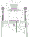
Fig. 1 is a schematic front view of the present invention.
Fig. 2 is a schematic diagram of a partial top view structure of the present invention.
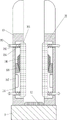
Fig. 3 is a partial left view structural diagram of the present invention.
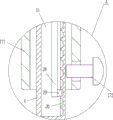
Fig. 4 is an enlarged schematic view of part a of the present invention.
FIG. 5 is a circuit diagram of the present invention.
FIG. 6 is a block diagram of the circuit of the present invention.
Wherein the figures include the following reference numerals: 1. a support plate, 2, a first guide rod, 3, a cross plate, 4, a movable plate, 5, a first guide hole, 6, a second guide hole, 7, a second guide rod, 8, a first spring, 9, a placing plate, 10, a side plate, 11, a first slot, 12, a backing plate, 13, a second spring, 14, a pressure sensor, 15, a control box, 16, a starting switch, 17, an emergency stop switch, 171, a sleeve plate, 172, a fastening bolt, 173, a driving motor, 174, a milling cutter, 175, a inching button, 18, a driving device, 181, a mounting plate, 182, a servo motor, 183, a gear, 184, a rack, 19, a clamping device, 191, a second slot, 192, a third guide hole, 193, a third slide rod, 194, a third spring, 195, a rubber plate, 196, a fixed oblique block, 197, an electric push rod, 198, a movable oblique block, 20, a sliding sleeve, 21, a limit plate, 22, a first bearing seat, 23, a threaded hole, 24. the screw rod 25, the special-shaped hole 26, the push block 27, the fourth spring 28, the movable rod 29, the clamping block 30, the clamping groove 31 and the third groove.
Detailed Description
Although the present invention may be described with respect to particular applications or industries, those skilled in the art will recognize the broader applicability of the invention. Those of ordinary skill in the art will recognize other factors such as: terms such as above, below, upward, downward, and the like are used to describe the accompanying drawings and are not meant to limit the scope of the invention, which is defined by the appended claims. Such as: any numerical designation of first or second, and the like, is merely exemplary and is not intended to limit the scope of the invention in any way.
Example 1
A wood board slotting device is shown in figures 1-6 and comprises a support plate 1, first guide rods 2, a transverse plate 3, a movable plate 4, second guide rods 7, first springs 8, a placing plate 9, side plates 10, a base plate 12, second springs 13, a pressure sensor 14, a control box 15, a starting switch 16, an emergency stop switch 17, a sleeve plate 171, a fastening bolt 172, a driving motor 173, a milling cutter 174, a jog button 175 and a driving device 18, wherein the support plate 1 is provided with two, the upper parts of the inner sides of the two support plates 1 are respectively connected with two first guide rods 2, the transverse plate 3 is connected between the two first guide rods 2 on the left side and the right side, the first guide rods 2 are connected with the transverse plate 3 in a welding connection mode, the movable plates 4 are arranged on the first guide rods 2 on the left side and the right side in a sliding mode, the front side and the rear side of the middle part of the movable plate 4 are respectively provided with first guide holes 5, the first guide rods 2 penetrate through the first guide, a second guide rod 7 is arranged in the second guide hole 6 in a sliding manner, a first spring 8 is connected between the bottom of the second guide rod 7 and the bottom of the transverse plate 3, the bottom of the second guide rod 7 penetrates through the first spring 8, the top of the left and right second guide rods 7 is connected with a placing plate 9, the second guide rod 7 is connected with the placing plate 9 in a welding connection manner, the front side and the rear side of the top of the placing plate 9 are both connected with side plates 10, a first open groove 11 is formed in the middle of the top of the placing plate 9, a plurality of second springs 13 are connected to the bottom of the first open groove 11, the top ends of all the second springs 13 are connected with a backing plate 12, the second springs 13 are connected with the backing plate 12 in a welding connection manner, the backing plate 12 is positioned in the first open groove 11, a pressure sensor 14 is connected to the middle of the bottom of the first open groove 11, the backing plate 12 is positioned above and, the upper portion of the right side of the right support plate 1 is connected with a starting switch 16 and an emergency stop switch 17, the starting switch 16 is located below the emergency stop switch 17, the upper portions of the movable plates 4 on the left side and the right side are both slidably sleeved with a sleeve plate 171, the lower portion of the outer side of the sleeve plate 171 is connected with a fastening bolt 172 through threads, the inner end of the fastening bolt 172 is in contact with the movable plate 4, the tops of the sleeve plates 171 on the left side and the right side are both provided with a driving motor 173, an output shaft of the driving motor 173 is connected with a milling cutter 174, the middle of the bottom of the placing plate 9 is connected with a jog.
Example 2
A wood board slotting device is shown in figures 1-6 and comprises a support plate 1, first guide rods 2, a transverse plate 3, a movable plate 4, second guide rods 7, first springs 8, a placing plate 9, side plates 10, a base plate 12, second springs 13, a pressure sensor 14, a control box 15, a starting switch 16, an emergency stop switch 17, a sleeve plate 171, a fastening bolt 172, a driving motor 173, a milling cutter 174, an inching button 175 and a driving device 18, wherein the support plate 1 is provided with two, the upper parts of the inner sides of the two support plates 1 are respectively connected with the two first guide rods 2, the transverse plate 3 is connected between the two first guide rods 2 on the left side and the right side, the movable plate 4 is arranged on the first guide rods 2 on the left side and the right side in a sliding manner, the front side and the back side of the middle part of the movable plate 4 are respectively provided with a first guide hole 5, the first guide rods 2 penetrate through the first guide holes 5, the left side and the right side of the middle, a first spring 8 is connected between the bottom of the second guide rod 7 and the bottom of the transverse plate 3, the bottom of the second guide rod 7 passes through the first spring 8, the top of the left and right second guide rods 7 is connected with a placing plate 9, the front and back sides of the top of the placing plate 9 are both connected with side plates 10, a first open slot 11 is formed in the middle of the top of the placing plate 9, a plurality of second springs 13 are connected to the bottom of the first open slot 11, the top ends of all the second springs 13 are connected with a backing plate 12, the backing plate 12 is positioned in the first open slot 11, a pressure sensor 14 is connected to the middle of the bottom of the first open slot 11, the backing plate 12 is positioned above and matched with the pressure sensor 14, the lower part of the left side of the right support plate 1 is connected with a control box 15, the upper part of the right side of the right support plate 1 is connected with a starting switch 16 and an emergency stop switch 17, the starting, the fastening bolt 172 is connected to the lower portion of the outer side of the sleeve plate 171 through a thread, the inner end of the fastening bolt 172 contacts with the movable plate 4, the driving motors 173 are installed on the top portions of the sleeve plates 171 on the left and right sides, the milling cutter 174 is connected to the output shaft of the driving motors 173, the inching button 175 is connected to the middle of the bottom of the placing plate 9, and the driving device 18 is arranged at the bottom of the transverse plate 3.
The driving device 18 comprises a mounting plate 181, a servo motor 182, a gear 183 and a rack 184, the mounting plate 181 is connected to the middle of the rear side of the bottom of the transverse plate 3, the transverse plate 3 is connected with the mounting plate 181 in a welding connection mode, the servo motor 182 is mounted on the lower portion of the front side of the mounting plate 181, the gear 183 is connected to an output shaft of the servo motor 182, the racks 184 are connected to the rear portions of the inner lower portions of the movable plates 4 on the left side and the right side, the movable plates 4 are connected with the racks 184 in a welding connection mode, the racks 184 are located behind the second guide rods 7, the left rack 184 is located above the gear 183, the right rack 184 is located below the gear 183.
Example 3
A wood board slotting device is shown in figures 1-6 and comprises a support plate 1, first guide rods 2, a transverse plate 3, a movable plate 4, second guide rods 7, first springs 8, a placing plate 9, side plates 10, a base plate 12, second springs 13, a pressure sensor 14, a control box 15, a starting switch 16, an emergency stop switch 17, a sleeve plate 171, a fastening bolt 172, a driving motor 173, a milling cutter 174, an inching button 175 and a driving device 18, wherein the support plate 1 is provided with two, the upper parts of the inner sides of the two support plates 1 are respectively connected with the two first guide rods 2, the transverse plate 3 is connected between the two first guide rods 2 on the left side and the right side, the movable plate 4 is arranged on the first guide rods 2 on the left side and the right side in a sliding manner, the front side and the back side of the middle part of the movable plate 4 are respectively provided with a first guide hole 5, the first guide rods 2 penetrate through the first guide holes 5, the left side and the right side of the middle, a first spring 8 is connected between the bottom of the second guide rod 7 and the bottom of the transverse plate 3, the bottom of the second guide rod 7 passes through the first spring 8, the top of the left and right second guide rods 7 is connected with a placing plate 9, the front and back sides of the top of the placing plate 9 are both connected with side plates 10, a first open slot 11 is formed in the middle of the top of the placing plate 9, a plurality of second springs 13 are connected to the bottom of the first open slot 11, the top ends of all the second springs 13 are connected with a backing plate 12, the backing plate 12 is positioned in the first open slot 11, a pressure sensor 14 is connected to the middle of the bottom of the first open slot 11, the backing plate 12 is positioned above and matched with the pressure sensor 14, the lower part of the left side of the right support plate 1 is connected with a control box 15, the upper part of the right side of the right support plate 1 is connected with a starting switch 16 and an emergency stop switch 17, the starting, the fastening bolt 172 is connected to the lower portion of the outer side of the sleeve plate 171 through a thread, the inner end of the fastening bolt 172 contacts with the movable plate 4, the driving motors 173 are installed on the top portions of the sleeve plates 171 on the left and right sides, the milling cutter 174 is connected to the output shaft of the driving motors 173, the inching button 175 is connected to the middle of the bottom of the placing plate 9, and the driving device 18 is arranged at the bottom of the transverse plate 3.
The driving device 18 comprises a mounting plate 181, a servo motor 182, a gear 183 and a rack 184, the mounting plate 181 is connected to the middle of the rear side of the bottom of the transverse plate 3, the servo motor 182 is mounted on the lower portion of the front side of the mounting plate 181, the gear 183 is connected to an output shaft of the servo motor 182, the racks 184 are connected to the rear portions of the inner lower portions of the movable plates 4 on the left side and the right side, the rack 184 is located behind the second guide rod 7, the left rack 184 is located above the gear 183, the right rack 184 is located below the gear 183, and the gear 183 is meshed with the.
The clamping device 19 is further included, the clamping device 19 includes a third sliding rod 193, a third spring 194, a rubber plate 195, a fixed oblique block 196, an electric push rod 197 and a movable oblique block 198, the inner sides of the side plates 10 on the front side and the rear side are respectively provided with a second slot 191, the upper and the lower parts of the side plates 10 are respectively provided with a third guide hole 192, the third guide holes 192 are communicated with the second slots 191, the third sliding rod 193 is arranged in the third guide holes 192 in a sliding manner, the rubber plate 195 is connected between the inner ends of the upper and the lower third sliding rods 193, two third springs 194 are connected between the outer sides of the rubber plate 195 and the inner sides of the second slots 191, the third sliding rod 193 penetrates through the third springs 194, the upper parts of the outer sides of the front and the rear rubber plates 195 are respectively connected with the fixed oblique block 196, the lower parts of the front side in the second slot 191 and the rear side in the second slot 191 on the front side are respectively connected with the electric push rod 197, the top of the telescopic, the movable ramp 198 is positioned below and in contact with the fixed ramp 196.
Example 4
A wood board slotting device is shown in figures 1-6 and comprises a support plate 1, first guide rods 2, a transverse plate 3, a movable plate 4, second guide rods 7, first springs 8, a placing plate 9, side plates 10, a base plate 12, second springs 13, a pressure sensor 14, a control box 15, a starting switch 16, an emergency stop switch 17, a sleeve plate 171, a fastening bolt 172, a driving motor 173, a milling cutter 174, an inching button 175 and a driving device 18, wherein the support plate 1 is provided with two, the upper parts of the inner sides of the two support plates 1 are respectively connected with the two first guide rods 2, the transverse plate 3 is connected between the two first guide rods 2 on the left side and the right side, the movable plate 4 is arranged on the first guide rods 2 on the left side and the right side in a sliding manner, the front side and the back side of the middle part of the movable plate 4 are respectively provided with a first guide hole 5, the first guide rods 2 penetrate through the first guide holes 5, the left side and the right side of the middle, a first spring 8 is connected between the bottom of the second guide rod 7 and the bottom of the transverse plate 3, the bottom of the second guide rod 7 passes through the first spring 8, the top of the left and right second guide rods 7 is connected with a placing plate 9, the front and back sides of the top of the placing plate 9 are both connected with side plates 10, a first open slot 11 is formed in the middle of the top of the placing plate 9, a plurality of second springs 13 are connected to the bottom of the first open slot 11, the top ends of all the second springs 13 are connected with a backing plate 12, the backing plate 12 is positioned in the first open slot 11, a pressure sensor 14 is connected to the middle of the bottom of the first open slot 11, the backing plate 12 is positioned above and matched with the pressure sensor 14, the lower part of the left side of the right support plate 1 is connected with a control box 15, the upper part of the right side of the right support plate 1 is connected with a starting switch 16 and an emergency stop switch 17, the starting, the fastening bolt 172 is connected to the lower portion of the outer side of the sleeve plate 171 through a thread, the inner end of the fastening bolt 172 contacts with the movable plate 4, the driving motors 173 are installed on the top portions of the sleeve plates 171 on the left and right sides, the milling cutter 174 is connected to the output shaft of the driving motors 173, the inching button 175 is connected to the middle of the bottom of the placing plate 9, and the driving device 18 is arranged at the bottom of the transverse plate 3.
The driving device 18 comprises a mounting plate 181, a servo motor 182, a gear 183 and a rack 184, the mounting plate 181 is connected to the middle of the rear side of the bottom of the transverse plate 3, the servo motor 182 is mounted on the lower portion of the front side of the mounting plate 181, the gear 183 is connected to an output shaft of the servo motor 182, the racks 184 are connected to the rear portions of the inner lower portions of the movable plates 4 on the left side and the right side, the rack 184 is located behind the second guide rod 7, the left rack 184 is located above the gear 183, the right rack 184 is located below the gear 183, and the gear 183 is meshed with the.
Also comprises a clamping device 19, the clamping device 19 comprises a third slide bar 193, a third spring 194 and a rubber plate 195, the inner sides of side plates 10 on the front side and the rear side are respectively provided with a second groove 191, the upper and lower parts of the side plates 10 are respectively provided with a third guide hole 192, the third guide holes 192 are communicated with the second grooves 191, a third sliding rod 193 is arranged in the third guide holes 192 in a sliding manner, a rubber plate 195 is connected between the inner ends of the upper and lower third sliding rods 193, two third springs 194 are connected between the outer side of the rubber plate 195 and the inner side of the second groove 191, the third sliding rod 193 penetrates through the third springs 194, the upper parts of the outer sides of the front and rear rubber plates 195 are respectively connected with a fixed oblique block 196, the lower parts of the front side in the front second groove 191 and the lower parts of the rear side in the rear second groove 191 are respectively connected with an electric push rod 197, the top of an expansion rod of the electric push rod 197 is connected with a movable oblique block 198, and the movable oblique block 198 is positioned below.
Still including sliding sleeve 20, limiting plate 21, primary shaft bearing 22 and threaded rod 24, sliding connection has sliding sleeve 20 on the second guide arm 7, sliding sleeve 20 is located diaphragm 3 top, be connected with limiting plate 21 between the sliding sleeve 20 of the left and right sides, sliding sleeve 20 is connected with limiting plate 21 through welded connection's mode, primary shaft bearing 22 has been inlayed to limiting plate 21's right part, threaded hole 23 is opened to diaphragm 3's right part, be equipped with threaded rod 24 in the threaded hole 23, threaded rod 24 is located rack 184 the place ahead, the top and the interior bearing of primary shaft bearing 22 of threaded rod 24 are connected.
Example 5
A wood board slotting device is shown in figures 1-6 and comprises a support plate 1, first guide rods 2, a transverse plate 3, a movable plate 4, second guide rods 7, first springs 8, a placing plate 9, side plates 10, a base plate 12, second springs 13, a pressure sensor 14, a control box 15, a starting switch 16, an emergency stop switch 17, a sleeve plate 171, a fastening bolt 172, a driving motor 173, a milling cutter 174, an inching button 175 and a driving device 18, wherein the support plate 1 is provided with two, the upper parts of the inner sides of the two support plates 1 are respectively connected with the two first guide rods 2, the transverse plate 3 is connected between the two first guide rods 2 on the left side and the right side, the movable plate 4 is arranged on the first guide rods 2 on the left side and the right side in a sliding manner, the front side and the back side of the middle part of the movable plate 4 are respectively provided with a first guide hole 5, the first guide rods 2 penetrate through the first guide holes 5, the left side and the right side of the middle, a first spring 8 is connected between the bottom of the second guide rod 7 and the bottom of the transverse plate 3, the bottom of the second guide rod 7 passes through the first spring 8, the top of the left and right second guide rods 7 is connected with a placing plate 9, the front and back sides of the top of the placing plate 9 are both connected with side plates 10, a first open slot 11 is formed in the middle of the top of the placing plate 9, a plurality of second springs 13 are connected to the bottom of the first open slot 11, the top ends of all the second springs 13 are connected with a backing plate 12, the backing plate 12 is positioned in the first open slot 11, a pressure sensor 14 is connected to the middle of the bottom of the first open slot 11, the backing plate 12 is positioned above and matched with the pressure sensor 14, the lower part of the left side of the right support plate 1 is connected with a control box 15, the upper part of the right side of the right support plate 1 is connected with a starting switch 16 and an emergency stop switch 17, the starting, the fastening bolt 172 is connected to the lower portion of the outer side of the sleeve plate 171 through a thread, the inner end of the fastening bolt 172 contacts with the movable plate 4, the driving motors 173 are installed on the top portions of the sleeve plates 171 on the left and right sides, the milling cutter 174 is connected to the output shaft of the driving motors 173, the inching button 175 is connected to the middle of the bottom of the placing plate 9, and the driving device 18 is arranged at the bottom of the transverse plate 3.
The driving device 18 comprises a mounting plate 181, a servo motor 182, a gear 183 and a rack 184, the mounting plate 181 is connected to the middle of the rear side of the bottom of the transverse plate 3, the servo motor 182 is mounted on the lower portion of the front side of the mounting plate 181, the gear 183 is connected to an output shaft of the servo motor 182, the racks 184 are connected to the rear portions of the inner lower portions of the movable plates 4 on the left side and the right side, the rack 184 is located behind the second guide rod 7, the left rack 184 is located above the gear 183, the right rack 184 is located below the gear 183, and the gear 183 is meshed with the.
Also comprises a clamping device 19, the clamping device 19 comprises a third slide bar 193, a third spring 194 and a rubber plate 195, the inner sides of side plates 10 on the front side and the rear side are respectively provided with a second groove 191, the upper and lower parts of the side plates 10 are respectively provided with a third guide hole 192, the third guide holes 192 are communicated with the second grooves 191, a third sliding rod 193 is arranged in the third guide holes 192 in a sliding manner, a rubber plate 195 is connected between the inner ends of the upper and lower third sliding rods 193, two third springs 194 are connected between the outer side of the rubber plate 195 and the inner side of the second groove 191, the third sliding rod 193 penetrates through the third springs 194, the upper parts of the outer sides of the front and rear rubber plates 195 are respectively connected with a fixed oblique block 196, the lower parts of the front side in the front second groove 191 and the lower parts of the rear side in the rear second groove 191 are respectively connected with an electric push rod 197, the top of an expansion rod of the electric push rod 197 is connected with a movable oblique block 198, and the movable oblique block 198 is positioned below.
The sliding sleeve is characterized by further comprising a sliding sleeve 20, a limiting plate 21, a first bearing seat 22 and a threaded rod 24, the sliding sleeve 20 is connected onto the second guide rod 7 in a sliding mode, the sliding sleeve 20 is located above the transverse plate 3, the limiting plate 21 is connected between the sliding sleeves 20 on the left side and the right side, the first bearing seat 22 is embedded into the right portion of the limiting plate 21, a threaded hole 23 is formed in the right portion of the transverse plate 3, the threaded rod 24 is arranged in the threaded hole 23, the threaded rod 24 is located in front of the rack 184, and the top of the threaded rod 24.
The movable plate is characterized by further comprising a push block 26, a fourth spring 27, a movable rod 28 and a fixture block 29, wherein the upper parts of the outer sides of the sleeve plates 171 on the left side and the right side are respectively provided with a special-shaped hole 25, the special-shaped holes 25 are communicated with the inner part of the sleeve plates 171, the push block 26 is arranged in the special-shaped holes 25, the inner side of the push block 26 is connected with the movable rod 28, the push block 26 is connected with the movable rod 28 in a welding connection mode, the upper part of the movable plate 4 is provided with a third opening 31, the lower part of the movable rod 28 is positioned in the third opening 31, two fourth springs 27 are connected between the upper part of the right side of the left movable rod 28 and the right wall in the left special-shaped hole 25, two fourth springs 27 are also connected between the upper part of the left side of the right movable rod 28 and the left wall in the right special-shaped hole 25, a plurality of clamping grooves 30 are uniformly formed in the left side of the third opening 31 and, the latch 29 is engaged with the latch groove 30.
The control box 15 comprises a switching power supply, a power supply module and a control module, the output end of the switching power supply is connected with the power supply module through a circuit, the switching power supply supplies power to the whole wood board slotting device, the power supply module is connected with the control module through a circuit, and the power supply module is connected with a power supply main switch through a circuit; the control module is connected with the starting switch 16, the emergency stop switch 17, the inching button 175 and the pressure sensor 14 through lines, and is connected with the driving motor 173, the electric push rod 197 and the servo motor 182 through peripheral circuits.
When the wood board needs to be grooved, an operator presses a power supply main switch to electrify the equipment, then adjusts the position of the milling cutter 174 according to the position of the wood board needing to be grooved, the operator rotates the fastening bolt 172 to move outwards without contacting with the movable plate 4, then the sleeve plate 171 can be moved upwards or downwards, the milling cutter 174 is driven to move upwards or downwards by the driving motor 173, the sleeve plate 171 stops moving after the milling cutter 174 moves to a proper position, then the fastening bolt 172 is rotated to move inwards to contact with the movable plate 4, so that the sleeve plate 171 can be fixed, namely the position of the milling cutter 174 is fixed, then the starting switch 16 is pressed, the starting switch 16 sends a signal, the control module receives the signal to control the driving motors 173 on the left side and the right side to start, so as to drive the milling cutter 174 to rotate, the operator places the wood board needing to be grooved on the middle position of the placing plate 9 between the front, after the wood board contacts the backing plate 12, the backing plate 12 is driven to move downwards under the action of the gravity of the wood board, the second spring 13 is compressed, after the backing plate 12 moves downwards and contacts the pressure sensor 14, the pressure sensor 14 sends a signal, the control module receives the signal and controls the driving device 18 to operate for 3 seconds after delaying for 1 second, the driving device 18 drives the movable plates 4 on the left side and the right side to move inwards, so that the milling cutters 174 on the left side and the right side are driven to move inwards through the sleeve plate 171 and the driving motor 173, the milling cutters 174 on the left side and the right side move inwards and rotate to groove the two sides of the wood board, then an operator presses the wood board downwards, so that the placing plate 9 is driven to move downwards, the inching button 175 and the second guide rod 7 are driven to move downwards, the first spring 8 is compressed, the milling cutters 174 can open long grooves on the left side and the right side of the wood board, when the inching button 175 moves downwards and contacts with the top of, after 1 second, the driving device 18 drives the movable plates 4 on the left side and the right side to move outwards and reset, so as to drive the milling cutter 174 to move outwards and reset, meanwhile, the operator loosens the wood board, the second guide rod 7 drives the placing plate 9 to move upwards and reset under the action of the first spring 8, so as to drive the grooved wood board to move upwards and reset, then, the operator takes the wood board off the placing plate 9, the backing plate 12 moves upwards and resets under the action of the second spring 13, the backing plate 12 is not in contact with the pressure sensor 14 any more, the control module controls the driving motor 173 to be turned off, so that the grooves can be simultaneously formed on the two sides of the wood board, the grooving efficiency is high, when the wood board needs to be grooved continuously, the operation can be carried out according to the above, when an emergency or an accident occurs in the grooving process, the emergency stop switch 17 can be pressed, and the control module controls all electric appliance, thus, accidents can be reduced. After the slotting is finished, the power main switch is pressed down again to cut off the power of the equipment.
After the base plate 12 is contacted with the pressure sensor 14, the control module controls the servo motor 182 to delay 1 second and rotate clockwise for 3 seconds, the servo motor 182 rotates clockwise to drive the gear 183 to rotate clockwise, thereby driving the upper rack 184 to move rightwards and driving the lower rack 184 to move leftwards, thereby driving the movable plates 4 at the left and right sides to move inwards, further driving the milling cutter 174 to move inwards through the driving motor 173, so as to groove the left and right sides of the wood board, when the inching button 175 is contacted with the transverse plate 3, the control module controls the servo motor 182 to delay 1 second and rotate anticlockwise for 3 seconds, the servo motor 182 rotates anticlockwise to drive the gear 183 to rotate anticlockwise, thereby driving the upper rack 184 to move leftwards and driving the lower rack 184 to move rightwards, so as to drive the milling cutter 174 to move outwards and reset, so as to conveniently groove the wood board, without moving the grooving machine by, manpower can be saved.
An operator places a wood board on the placing plate 9 between the front side plate and the rear side plate 10, when the backing plate 12 presses the pressure sensor 14, the control module controls the electric push rods 197 in the front and rear directions to extend for 1 second, so as to drive the movable oblique block 198 to move upwards, so that the rubber plates 195 in the front and rear sides are driven to move inwards through the fixed oblique block 196, the third spring 194 is stretched, the rubber plates 195 in the front and rear sides move inwards to clamp and fix the wood board, so as to prevent the wood board from moving backwards and forwards and causing no straight grooving in the wood board grooving process, after the inching button 175 is contacted with the transverse plate 3, the control module controls the electric push rods 197 to delay for 4 seconds and shorten for 1 second, the electric push rods 197 shorten to drive the movable oblique block 198 to move downwards, the movable oblique block 198 does not press the fixed oblique block 196 any more, the rubber plates 195 in the front and rear sides move outwards to reset under the action, after the wood board moves upwards and resets, the operator can take the grooved wood board off the placing board 9.
When people need transfer the fluting length of plank hour, operating personnel anticlockwise rotation threaded rod 24, under the cooperation of screw hole 23, threaded rod 24 rebound, thereby drive limiting plate 21 rebound through first bearing frame 22, stop rotating threaded rod 24 after limiting plate 21 moves to suitable position, distance between inching button 175 and the limiting plate 21 shortens, the fluting length of plank is the distance between inching button 175 and the limiting plate 21, so, can be through the position control plank fluting length of adjusting limiting plate 21, when needs transfer the fluting length of plank big, operating personnel clockwise rotation threaded rod 24 drive limiting plate 21 downstream to suitable position can.
Firstly, the fastening bolt 172 is rotated to move outwards without contacting the movable plate 4, when the grooving position of the wood board needs to be adjusted, an operator presses the push block 26 inwards to drive the movable rod 28 to move inwards, the fourth spring 27 is compressed, the movable rod 28 drives the clamping block 29 to move inwards, so that the open block is moved out of the clamping groove 30, then the sleeve plate 171 can be moved upwards or downwards to drive the milling cutter 174 and the clamping block 29 to move upwards or downwards, when the milling cutter 174 moves to a proper position, the sleeve plate 171 stops moving, then the push block 26 is loosened, under the action of the fourth spring 27, the movable rod 28 drives the push block 26 and the clamping block 29 to move outwards, so that the clamping block 29 is clamped into the clamping groove 30, so that the position of the sleeve plate 171 is fixed, namely the height of the milling cutter 174 is fixed, and thus the height of the milling cutter 174 can be conveniently adjusted, and the grooving operation is simpler.
The above description is only an example of the present invention and is not intended to limit the present invention. All equivalents which come within the spirit of the invention are therefore intended to be embraced therein. Details not described herein are well within the skill of those in the art.
Claims (6)
1. A wood board slotting device comprises two support plates, two first guide rods, a transverse plate, a movable plate, a second guide rod, a first spring, a placing plate, side plates, a backing plate, a second spring and a pressure sensor, wherein the two support plates are arranged, the upper parts of the inner sides of the two support plates are respectively connected with the two first guide rods, the transverse plate is connected between the two first guide rods on the left side and the right side, the movable plate is arranged on the first guide rods on the left side and the right side in a sliding manner, first guide holes are formed in the front side and the rear side of the middle part of the movable plate, the first guide rods penetrate through the first guide holes, second guide holes are formed in the left side and the right side of the middle part of the transverse plate, the second guide rods are arranged in the second guide holes in a sliding manner, the first springs are connected between the bottoms of the second guide rods and the bottom of the transverse plate, the first, it has first fluting to place the top centre of board, and the bottom is connected with many second springs in the first fluting, and the top of all second springs is connected with the backing plate, and the backing plate is located first fluting, and bottom intermediate junction has pressure sensor in the first fluting, and the backing plate is located pressure sensor top and rather than cooperation, its characterized in that: still including the control box, starting switch, the scram switch, the lagging, fastening bolt, driving motor, milling cutter, inching button and drive arrangement, the left side sub-unit connection of right-hand extension board has the control box, the right side upper portion of right-hand extension board is connected with starting switch and scram switch, starting switch is located the below of scram switch, the equal slidingtype cover in fly leaf upper portion of controlling both sides has the lagging, there is fastening bolt outside lower part of lagging through threaded connection, fastening bolt's the inner contacts with the fly leaf, driving motor is all installed at the lagging top of the left and right sides, be connected with milling cutter on driving motor's the output shaft, the bottom intermediate junction who places the board has inching button, the bottom of diaphragm is equipped with drive arrangement.
2. A wood grooving device as claimed in claim 1 wherein: the driving device comprises a mounting plate, a servo motor, a gear and a rack, the mounting plate is connected to the middle of the rear side of the bottom of the transverse plate, the servo motor is installed on the lower portion of the front side of the mounting plate, the gear is connected to an output shaft of the servo motor, the racks are connected to the rear portions of the lower portions of the inner sides of the movable plates of the left side and the right side, the racks are located behind the second guide rod, the left rack is located above the gear, the right rack is located below the gear, and the gear is.
3. A wood grooving device as claimed in claim 2 wherein: the electric push rod is characterized by further comprising a clamping device, the clamping device comprises a third sliding rod, a third spring, a rubber plate, a fixed oblique block, an electric push rod and a movable oblique block, second grooves are formed in the inner sides of the side plates on the front side and the rear side, third guide holes are formed in the upper portion and the lower portion of each side plate, the third guide holes are communicated with the second grooves, the third sliding rod is arranged in each third guide hole in a sliding mode, the rubber plate is connected between the inner ends of the upper third sliding rod and the lower third sliding rod, two third springs are connected between the outer side of the rubber plate and the inner side of the second groove, the third sliding rod penetrates through the third springs, the upper portion of the outer side of the front rubber plate and the upper portion of the outer side of the rear rubber plate are connected with the fixed oblique block, the lower portion of the front side in the second groove in the front side and the lower portion.
4. A wood grooving device as claimed in claim 3 wherein: still including sliding sleeve, limiting plate, primary shaft bearing and threaded rod, sliding connection has the sliding sleeve on the second guide arm, and the sliding sleeve is located the diaphragm top, is connected with the limiting plate between the sliding sleeve of the left and right sides, and primary shaft bearing has been inlayed to the right part of limiting plate, and threaded hole is opened to the right part of diaphragm, and threaded hole is equipped with the threaded rod, and the threaded rod is located rack the place ahead, and the top and the interior bearing of primary shaft bearing of threaded rod are connected.
5. A wood grooving device as claimed in claim 4 wherein: still including the ejector pad, the fourth spring, movable rod and fixture block, the lagging outside upper portion of the left and right sides has all opened the dysmorphism hole, communicate in dysmorphism hole and the lagging, the downthehole ejector pad that is equipped with of dysmorphism, the ejector pad inboard is connected with the movable rod, fly leaf upper portion is opened there is the third fluting, the movable rod lower part is located the third fluting, be connected with two fourth springs between upper portion of left movable rod right side and the downthehole right wall of left dysmorphism, also be connected with two fourth springs between upper portion of right-hand movable rod left side and the downthehole left wall of right-hand dysmorphism, left side and right-hand third fluting are all evenly opened on the right side in the inslot has a plurality of draw-in grooves, the movable rod outside.
6. A wood grooving device as claimed in claim 5 wherein: the control box comprises a switching power supply, a power supply module and a control module, the output end of the switching power supply is connected with the power supply module through a circuit, the switching power supply supplies power to the whole wood board slotting device, the power supply module is connected with the control module through a circuit, and the power supply module is connected with a power supply main switch through a circuit; the control module is connected with the starting switch, the emergency stop switch, the inching button and the pressure sensor through circuits, and is connected with the driving motor, the electric push rod and the servo motor through a peripheral circuit.
Priority Applications (1)
| Application Number | Priority Date | Filing Date | Title |
|---|---|---|---|
| CN201910729891.7A CN110549438B (en) | 2019-08-08 | 2019-08-08 | Wood board grooving device |
Applications Claiming Priority (1)
| Application Number | Priority Date | Filing Date | Title |
|---|---|---|---|
| CN201910729891.7A CN110549438B (en) | 2019-08-08 | 2019-08-08 | Wood board grooving device |
Publications (2)
| Publication Number | Publication Date |
|---|---|
| CN110549438A CN110549438A (en) | 2019-12-10 |
| CN110549438B true CN110549438B (en) | 2021-06-22 |
Family
ID=68737217
Family Applications (1)
| Application Number | Title | Priority Date | Filing Date |
|---|---|---|---|
| CN201910729891.7A Active CN110549438B (en) | 2019-08-08 | 2019-08-08 | Wood board grooving device |
Country Status (1)
| Country | Link |
|---|---|
| CN (1) | CN110549438B (en) |
Families Citing this family (2)
| Publication number | Priority date | Publication date | Assignee | Title |
|---|---|---|---|---|
| CN112829018A (en) * | 2021-01-12 | 2021-05-25 | 何强 | Double-sided accurate slotting equipment for assembling wood artware |
| CN114800731A (en) * | 2022-04-12 | 2022-07-29 | 江苏恒源园艺用品有限公司 | Gardening support rod double-side groove milling and cutting machine for greening protection and cutting process |
Citations (7)
| Publication number | Priority date | Publication date | Assignee | Title |
|---|---|---|---|---|
| JP2006263868A (en) * | 2005-03-24 | 2006-10-05 | System Planning:Kk | Manufacturing device and method of screw point and screw point |
| CN201505843U (en) * | 2009-09-16 | 2010-06-16 | 姚龙江 | Vertical grooving machine |
| CN204054241U (en) * | 2014-09-09 | 2014-12-31 | 重庆远东门窗有限公司 | Band regulates carpenter's vertical milling machine of spacing feeding structure |
| CN206263647U (en) * | 2016-12-15 | 2017-06-20 | 攀枝花市蓝天锻造有限公司 | A kind of inclined surface clamp device |
| CN206393660U (en) * | 2016-12-22 | 2017-08-11 | 周忠臣 | One kind efficiently removes brick manipulator |
| CN108214464A (en) * | 2018-02-06 | 2018-06-29 | 苏州功业肆点零智能科技有限公司 | A kind of compound clamp arm of industrial robot |
| CN109531729A (en) * | 2018-12-11 | 2019-03-29 | 赣州市南康区万家源家具有限公司 | Frame in furniture grooving tool |
Family Cites Families (1)
| Publication number | Priority date | Publication date | Assignee | Title |
|---|---|---|---|---|
| KR100596162B1 (en) * | 2005-12-12 | 2006-07-04 | 매일유업주식회사 | Apparatus for forming a slot using a milling machine |
-
2019
- 2019-08-08 CN CN201910729891.7A patent/CN110549438B/en active Active
Patent Citations (7)
| Publication number | Priority date | Publication date | Assignee | Title |
|---|---|---|---|---|
| JP2006263868A (en) * | 2005-03-24 | 2006-10-05 | System Planning:Kk | Manufacturing device and method of screw point and screw point |
| CN201505843U (en) * | 2009-09-16 | 2010-06-16 | 姚龙江 | Vertical grooving machine |
| CN204054241U (en) * | 2014-09-09 | 2014-12-31 | 重庆远东门窗有限公司 | Band regulates carpenter's vertical milling machine of spacing feeding structure |
| CN206263647U (en) * | 2016-12-15 | 2017-06-20 | 攀枝花市蓝天锻造有限公司 | A kind of inclined surface clamp device |
| CN206393660U (en) * | 2016-12-22 | 2017-08-11 | 周忠臣 | One kind efficiently removes brick manipulator |
| CN108214464A (en) * | 2018-02-06 | 2018-06-29 | 苏州功业肆点零智能科技有限公司 | A kind of compound clamp arm of industrial robot |
| CN109531729A (en) * | 2018-12-11 | 2019-03-29 | 赣州市南康区万家源家具有限公司 | Frame in furniture grooving tool |
Also Published As
| Publication number | Publication date |
|---|---|
| CN110549438A (en) | 2019-12-10 |
Similar Documents
| Publication | Publication Date | Title |
|---|---|---|
| CN103286831B (en) | Numerical control woodworking lathe and carving multifunctional all-in-one machine | |
| CN110549438B (en) | Wood board grooving device | |
| CN210677900U (en) | Multi-angle hole milling device for refrigerator handle | |
| CN110587716A (en) | Furniture production is with solid board cutting former | |
| CN211661229U (en) | Sawing machine equipment | |
| CN113084884B (en) | Cutting device is used in intention product packaging design | |
| CN204366100U (en) | Motor holding shaft watt hole special boring mill | |
| CN210789418U (en) | Keyway planer | |
| CN116038823B (en) | Adjustable cutting machine for wooden plates | |
| CN210061629U (en) | Fixed length value adjustable slabstone cutting machine | |
| KR101744675B1 (en) | V-cutting Machine | |
| CN112518037A (en) | Workbench for machining mechanical parts | |
| CN215615297U (en) | Drilling equipment is used in processing of high-accuracy mould | |
| CN211306617U (en) | Multifunctional numerical control woodworking machine tool | |
| CN104400058A (en) | Special boring lathe for axle hole of engine body | |
| CN210758203U (en) | Panel cutting and sawing equipment | |
| CN110774378A (en) | Multifunctional numerical control woodworking machine tool | |
| CN111975921A (en) | Automatic grinding and cutting production line for wood bed raw materials | |
| CN216729670U (en) | Drilling machine for middle support of motor train unit seat | |
| CN214349817U (en) | Punching die accessory drilling equipment | |
| CN219094458U (en) | Numerical control planer-type double-end milling machine cutter changes structure | |
| CN219504254U (en) | Feeding equipment of metal cutting forming machine tool | |
| CN204366588U (en) | The pay-off of motor holding shaft watt hole special boring mill | |
| CN217292662U (en) | Novel sliding table saw for material processing production | |
| CN220445809U (en) | Adjustable stamping die end face milling jig |
Legal Events
| Date | Code | Title | Description |
|---|---|---|---|
| PB01 | Publication | ||
| PB01 | Publication | ||
| SE01 | Entry into force of request for substantive examination | ||
| SE01 | Entry into force of request for substantive examination | ||
| CB03 | Change of inventor or designer information | ||
| CB03 | Change of inventor or designer information |
Inventor after: Lin Xiaozhen Inventor before: Dong Lei |
|
| CB02 | Change of applicant information | ||
| CB02 | Change of applicant information |
Address after: 510030 402, 47 Caiyuan West, Zhongshan 2nd Road, Yuexiu District, Guangzhou City, Guangdong Province Applicant after: Dong Lei Address before: No.1, East 1st ring road, Hantai District, Hanzhong City, Shaanxi Province Applicant before: Dong Lei |
|
| GR01 | Patent grant | ||
| GR01 | Patent grant |