CN110542242B - Combined cycle heat pump device - Google Patents
Combined cycle heat pump device Download PDFInfo
- Publication number
- CN110542242B CN110542242B CN201910455857.5A CN201910455857A CN110542242B CN 110542242 B CN110542242 B CN 110542242B CN 201910455857 A CN201910455857 A CN 201910455857A CN 110542242 B CN110542242 B CN 110542242B
- Authority
- CN
- China
- Prior art keywords
- communicated
- heat
- expander
- medium
- temperature evaporator
- Prior art date
- Legal status (The legal status is an assumption and is not a legal conclusion. Google has not performed a legal analysis and makes no representation as to the accuracy of the status listed.)
- Active
Links
Images


Classifications
-
- F—MECHANICAL ENGINEERING; LIGHTING; HEATING; WEAPONS; BLASTING
- F25—REFRIGERATION OR COOLING; COMBINED HEATING AND REFRIGERATION SYSTEMS; HEAT PUMP SYSTEMS; MANUFACTURE OR STORAGE OF ICE; LIQUEFACTION SOLIDIFICATION OF GASES
- F25B—REFRIGERATION MACHINES, PLANTS OR SYSTEMS; COMBINED HEATING AND REFRIGERATION SYSTEMS; HEAT PUMP SYSTEMS
- F25B25/00—Machines, plants or systems, using a combination of modes of operation covered by two or more of the groups F25B1/00 - F25B23/00
-
- F—MECHANICAL ENGINEERING; LIGHTING; HEATING; WEAPONS; BLASTING
- F25—REFRIGERATION OR COOLING; COMBINED HEATING AND REFRIGERATION SYSTEMS; HEAT PUMP SYSTEMS; MANUFACTURE OR STORAGE OF ICE; LIQUEFACTION SOLIDIFICATION OF GASES
- F25B—REFRIGERATION MACHINES, PLANTS OR SYSTEMS; COMBINED HEATING AND REFRIGERATION SYSTEMS; HEAT PUMP SYSTEMS
- F25B29/00—Combined heating and refrigeration systems, e.g. operating alternately or simultaneously
- F25B29/003—Combined heating and refrigeration systems, e.g. operating alternately or simultaneously of the compression type system
Abstract
The invention provides a combined cycle heat pump device, and belongs to the technical field of energy power and heat pumps. An air channel is arranged outside and is communicated with a combustion chamber through a compressor, a fuel channel is arranged outside and is communicated with the combustion chamber, a fuel gas channel is arranged in the combustion chamber and is communicated with the outside through a gas turbine, a medium-temperature evaporator and a low-temperature evaporator, a heat supply device is communicated with the low-temperature evaporator through a circulating pump, the low-temperature evaporator is communicated with an expander, the heat supply device is communicated with the medium-temperature evaporator through a second circulating pump, the medium-temperature evaporator is communicated with a second expander, and the expander and a third expander are communicated with the heat supply device; the second compressor is communicated with a second heat supply device, the second heat supply device is communicated with the evaporator through the throttle valve, and the evaporator is communicated with the second compressor; the medium temperature evaporator is provided with a heat source medium channel, the heat supply device and the second heat supply device are provided with heated medium channels, the evaporator is provided with a low temperature heat medium channel which is respectively communicated with the outside, and the gas turbine, the expander and the second expander are connected with the compressor and the second compressor and transmit power to form the combined cycle heat pump device.
Description
The technical field is as follows:
the invention belongs to the technical field of energy power and heat pumps.
Background art:
cold demand, heat demand and power demand, which are common in human life and production; in reality, people often need to directly utilize high-quality fuel to realize refrigeration, heat supply or convert the high-quality fuel into power, and also need to utilize the power to refrigerate or utilize the power and combine low-temperature heat energy to supply heat. In achieving the above objects, various considerations or conditional limitations are faced, including the type, grade and quantity of energy sources, the type, grade and quantity of user demands, ambient temperature, the type of working medium, the flow, structure and manufacturing cost of the equipment, and so on. In this regard, it is desirable to achieve the objective of actively and maximally utilizing energy with relatively simple technical means in terms of energy supply and user demand.
In the field of refrigeration or heating, aiming at the situation that source fuels are liquid fuels and natural gas, the traditional technical route is that high-efficiency utilization of energy is realized by adopting a heat/electricity/cold combined supply technical means according to an energy gradient utilization principle, such a technical scheme is passive, complex and high in cost, and the application range of the technical scheme is also greatly limited. Therefore, the combined cycle heat pump device has the advantages of full temperature difference utilization, reasonable structure, wide working parameter range, initiative, simplicity, low cost and wider application range, and aims to realize high-efficiency refrigeration/heating by utilizing high-quality fuel and consider or give consideration to the requirements of effective utilization of mechanical energy or power output.
The invention content is as follows:
the invention mainly aims to provide a combined cycle heat pump device, and the specific contents of the invention are set forth in the following sections:
1. the combined cycle heat pump device mainly comprises a compressor, a gas turbine, a combustion chamber, an expander, a second expander, a circulating pump, a second circulating pump, a heat supply device, a low-temperature evaporator, a medium-temperature evaporator, a second compressor, a third expander and a second heat supply device; the heat supplier has condensed liquid pipeline connected via circulating pump to the low temperature evaporator, which has also steam passage connected to the expander, and the expander has also steam passage connected to the heat supplier; the heat supplier also has a condensate pipeline which is communicated with the intermediate temperature evaporator through a second circulating pump, then the intermediate temperature evaporator is also communicated with a second expander through a steam channel, and the second expander is also communicated with the heat supplier through a steam channel; the external part of the compressor is provided with an air channel communicated with the compressor, the compressor is also provided with an air channel communicated with the combustion chamber, the external part of the compressor is also provided with a fuel channel communicated with the combustion chamber, the combustion chamber is also provided with a gas channel communicated with the gas turbine, and the gas turbine is also provided with a gas channel communicated with the external part through the medium-temperature evaporator and the low-temperature evaporator; the external part is provided with a low-temperature heat medium channel which is communicated with a second compressor, the second compressor is also provided with a low-temperature heat medium channel which is communicated with a third expander through a second heat supply device, and the third expander is also provided with a low-temperature heat medium channel which is communicated with the external part; the heat supply device and the second heat supply device are also respectively communicated with the outside through heated medium channels, and the gas turbine, the expander, the second expander and the third expander are connected with the compressor and the second compressor and transmit power to form the combined cycle heat pump device.
2. The combined cycle heat pump device mainly comprises a compressor, a gas turbine, a combustion chamber, an expander, a second expander, a circulating pump, a second circulating pump, a heat supplier, a low-temperature evaporator, a medium-temperature evaporator, a second compressor, a third expander, a second heat supplier and a low-temperature heat regenerator; the heat supplier has condensed liquid pipeline connected via circulating pump to the low temperature evaporator, which has also steam passage connected to the expander, and the expander has also steam passage connected to the heat supplier; the heat supplier also has a condensate pipeline which is communicated with the intermediate temperature evaporator through a second circulating pump, then the intermediate temperature evaporator is also communicated with a second expander through a steam channel, and the second expander is also communicated with the heat supplier through a steam channel; the external part is provided with an air channel communicated with the compressor, the compressor is also provided with an air channel communicated with the combustion chamber, the external part is also provided with a fuel channel communicated with the combustion chamber, the combustion chamber is also provided with a gas channel communicated with the gas turbine, and the gas turbine is also provided with a gas channel communicated with the external part through the medium-temperature evaporator and the low-temperature evaporator; the external part of the expansion machine is provided with a low-temperature heat medium channel which is communicated with a second compressor through a low-temperature heat regenerator, the second compressor is also provided with a low-temperature heat medium channel which is communicated with a third expansion machine through a second heat supply device and the low-temperature heat regenerator, and the third expansion machine is also provided with a low-temperature heat medium channel which is communicated with the external part; the heat supply device and the second heat supply device are also respectively communicated with the outside through heated medium channels, and the gas turbine, the expander, the second expander and the third expander are connected with the compressor and the second compressor and transmit power to form the combined cycle heat pump device.
3. The combined cycle heat pump device mainly comprises a compressor, a gas turbine, a combustion chamber, an expander, a second expander, a circulating pump, a second circulating pump, a heat supplier, a low-temperature evaporator, a medium-temperature evaporator, a second compressor, a third expander, a second heat supplier and a low-temperature heat exchanger; the heat supplier has condensed liquid pipeline connected via circulating pump to the low temperature evaporator, which has also steam passage connected to the expander, and the expander has also steam passage connected to the heat supplier; the heat supplier also has a condensate pipeline which is communicated with the intermediate temperature evaporator through a second circulating pump, then the intermediate temperature evaporator is also communicated with a second expander through a steam channel, and the second expander is also communicated with the heat supplier through a steam channel; the external part is provided with an air channel communicated with the compressor, the compressor is also provided with an air channel communicated with the combustion chamber, the external part is also provided with a fuel channel communicated with the combustion chamber, the combustion chamber is also provided with a gas channel communicated with the gas turbine, and the gas turbine is also provided with a gas channel communicated with the external part through the medium-temperature evaporator and the low-temperature evaporator; the second compressor is provided with a circulating medium channel which is communicated with a third expander through a second heat supply device, and the third expander is also provided with a circulating medium channel which is communicated with the second compressor through a low-temperature heat exchanger; the heat supply device and the second heat supply device are also respectively communicated with the outside through heated medium channels, the low-temperature heat exchanger is also communicated with the outside through a low-temperature heat medium channel, and the gas turbine, the expander, the second expander and the third expander are connected with the compressor and the second compressor and transmit power to form the combined cycle heat pump device.
4. The combined cycle heat pump device mainly comprises a compressor, a gas turbine, a combustion chamber, an expander, a second expander, a circulating pump, a second circulating pump, a heat supply device, a low-temperature evaporator, a medium-temperature evaporator, a second compressor, a third expander, a second heat supply device, a low-temperature heat regenerator and a low-temperature heat exchanger; the heat supplier has condensed liquid pipeline connected via circulating pump to the low temperature evaporator, which has also steam passage connected to the expander, and the expander has also steam passage connected to the heat supplier; the heat supplier is also provided with a condensate pipeline which is communicated with the medium temperature evaporator through a second circulating pump, then the medium temperature evaporator is provided with a steam channel which is communicated with a second expander, and the second expander is also provided with a steam channel which is communicated with the heat supplier; the external part is provided with an air channel communicated with the compressor, the compressor is also provided with an air channel communicated with the combustion chamber, the external part is also provided with a fuel channel communicated with the combustion chamber, the combustion chamber is also provided with a gas channel communicated with the gas turbine, and the gas turbine is also provided with a gas channel communicated with the external part through the medium-temperature evaporator and the low-temperature evaporator; the second compressor is provided with a circulating medium channel which is communicated with a third expander through a second heat supplier and a low-temperature heat regenerator, and the third expander is also provided with a circulating medium channel which is communicated with the second compressor through a low-temperature heat exchanger and a low-temperature heat regenerator; the heat supply device and the second heat supply device are also respectively communicated with the outside through heated medium channels, the low-temperature heat exchanger is also communicated with the outside through a low-temperature heat medium channel, and the gas turbine, the expander, the second expander and the third expander are connected with the compressor and the second compressor and transmit power to form the combined cycle heat pump device.
5. The combined cycle heat pump device mainly comprises a compressor, a gas turbine, a combustion chamber, an expander, a second expander, a circulating pump, a second circulating pump, a heat supply device, a low-temperature evaporator, a medium-temperature evaporator, a second compressor, a second heat supply device, a throttle valve and an evaporator; the heat supplier has condensed liquid pipeline connected via circulating pump to the low temperature evaporator, which has also steam passage connected to the expander, and the expander has also steam passage connected to the heat supplier; the heat supplier is also provided with a condensate pipeline which is communicated with the medium temperature evaporator through a second circulating pump, then the medium temperature evaporator is provided with a steam channel which is communicated with a second expander, and the second expander is also provided with a steam channel which is communicated with the heat supplier; the external part of the compressor is provided with an air channel communicated with the compressor, the compressor is also provided with an air channel communicated with the combustion chamber, the external part of the compressor is also provided with a fuel channel communicated with the combustion chamber, the combustion chamber is also provided with a gas channel communicated with the gas turbine, and the gas turbine is also provided with a gas channel communicated with the external part through the medium-temperature evaporator and the low-temperature evaporator; the second compressor is provided with a circulating medium channel which is communicated with a second heat supplier, the second heat supplier is also provided with a circulating medium channel which is communicated with the evaporator through a throttle valve, and the evaporator is also provided with a circulating medium channel which is communicated with the second compressor; the heat supply device and the second heat supply device are also respectively communicated with the outside through heated medium channels, the evaporator is also communicated with the outside through low-temperature heat medium channels, and the gas turbine, the expander and the second expander are connected with the compressor and the second compressor and transmit power to form the combined cycle heat pump device.
6. A combined cycle heat pump device is characterized in that a heat regenerator and a third circulating pump are added in any combined cycle heat pump device in items 1-5, a condensing liquid pipeline of the heat regenerator is communicated with a low-temperature evaporator through the circulating pump, the heat regenerator is adjusted to be provided with a condensing liquid pipeline which is communicated with the heat regenerator through the circulating pump, an expansion machine or a second expansion machine is additionally provided with a steam extraction channel which is communicated with the heat regenerator, and the heat regenerator is provided with a condensing liquid pipeline which is communicated with the low-temperature evaporator through the third circulating pump, so that the combined cycle heat pump device is formed.
7. A combined cycle heat pump device is characterized in that a heat regenerator and a third circulating pump are added in any combined cycle heat pump device in items 1-5, a heat supplier is adjusted to be provided with a condensate pipeline communicated with a medium temperature evaporator through the second circulating pump, the heat supplier is provided with a condensate pipeline communicated with the heat regenerator through the second circulating pump, an expander or a second expander is additionally provided with a steam extraction channel communicated with the heat regenerator, the heat regenerator is provided with a condensate pipeline communicated with the medium temperature evaporator through the third circulating pump, and the combined cycle heat pump device is formed.
8. A combined cycle heat pump device is characterized in that a heat regenerator, a second heat regenerator, a third circulating pump and a fourth circulating pump are added in any combined cycle heat pump device of items 1 to 5, a heat supplier is adjusted to be provided with a condensate pipeline which is communicated with a low-temperature evaporator through the circulating pump, the heat supplier is provided with a condensate pipeline which is communicated with the heat regenerator through the circulating pump, an expander or a second expander is additionally provided with a steam extraction channel which is communicated with the heat regenerator, and the heat regenerator is provided with a condensate pipeline which is communicated with the low-temperature evaporator through the third circulating pump; a condensing liquid pipeline of the heat supplier is communicated with the intermediate temperature evaporator through a second circulating pump, and is adjusted to be communicated with the second heat regenerator through the second circulating pump, a steam extraction channel is additionally arranged on the expansion machine or the second expansion machine and is communicated with the second heat regenerator, and the condensing liquid pipeline of the second heat regenerator is communicated with the intermediate temperature evaporator through a fourth circulating pump, so that the combined cycle heat pump device is formed.
9. A combined cycle heat pump device, wherein a preheater is added in any one of the combined cycle heat pump devices of items 1 to 5, a heat supply device is adjusted to be provided with a condensate pipeline communicated with a low-temperature evaporator through a circulating pump, the heat supply device is provided with a condensate pipeline communicated with the low-temperature evaporator through the circulating pump and the preheater, and the preheater is also provided with a heat source medium channel communicated with the outside to form the combined cycle heat pump device.
10. A combined cycle heat pump device, wherein a preheater is added in any one of the combined cycle heat pump devices of items 1 to 5, a condensate pipeline of a heat supplier is communicated with a medium temperature evaporator through a second circulating pump, and is adjusted to be communicated with the medium temperature evaporator through the second circulating pump and the preheater, and a heat source medium channel of the preheater is communicated with the outside to form the combined cycle heat pump device.
11. A combined cycle heat pump device, wherein a preheater and a second preheater are added in any combined cycle heat pump device described in items 1-5, a heat supply device is adjusted to have a condensate pipeline communicated with a low temperature evaporator through a circulating pump, the heat supply device has a condensate pipeline communicated with the low temperature evaporator through the circulating pump and the preheater, the heat supply device has a condensate pipeline communicated with a medium temperature evaporator through the second circulating pump, the heat supply device has a condensate pipeline communicated with the medium temperature evaporator through the second circulating pump and the second preheater, the preheater and the second preheater are respectively provided with a heat source medium channel communicated with the outside, and the combined cycle heat pump device is formed.
12. A combined cycle heat pump device is characterized in that a preheater and a second preheater are added in any combined cycle heat pump device in items 1-5, a heat supply device is provided with a condensate pipeline which is communicated with a low-temperature evaporator through a circulating pump, the heat supply device is provided with a condensate pipeline which is communicated with a medium-temperature evaporator through a second circulating pump, the heat supply device is adjusted into two paths after the condensate pipeline passes through the circulating pump and the preheater, the first path is directly communicated with the low-temperature evaporator, the second path is communicated with the medium-temperature evaporator through the second circulating pump and the second preheater, and the preheater and the second preheater are respectively communicated with the outside through a heat source medium channel to form the combined cycle heat pump device.
13. A combined cycle heat pump device, wherein an intermediate reheater is added to any one of the combined cycle heat pump devices described in items 1 to 12, a steam passage of a medium temperature evaporator is communicated with a second expander, a steam passage of the second expander is communicated with a heat supply device, and the intermediate temperature evaporator is adjusted to be communicated with the second expander through the steam passage of the medium temperature evaporator, the second expander and an intermediate reheater steam passage are communicated with the second expander through the intermediate reheater, the second expander and the steam passage are communicated with the heat supply device, and the intermediate reheater and a heat source medium passage are communicated with the outside to form the combined cycle heat pump device.
14. A combined cycle heat pump device is characterized in that a third heat supply device is added in any combined cycle heat pump device in items 1-5, a second expander is communicated with the heat supply device through a steam channel, the second expander is communicated with the third heat supply device through a steam channel, the heat supply device is communicated with a medium temperature evaporator through a second circulating pump through a condensate pipeline, the third heat supply device is communicated with the medium temperature evaporator through a second circulating pump through a condensate pipeline, and the third heat supply device is also communicated with the outside through a heated medium channel to form the combined cycle heat pump device.
15. A combined cycle heat pump device is characterized in that a high-temperature heat regenerator is added in any combined cycle heat pump device in items 1 to 14, an air channel of a compressor is communicated with a combustion chamber and adjusted to be communicated with the combustion chamber through the high-temperature heat regenerator, a gas channel of a gas turbine is communicated with the outside through a medium-temperature evaporator and a low-temperature evaporator and adjusted to be communicated with the outside through the high-temperature heat regenerator, the medium-temperature evaporator and the low-temperature evaporator, and a gas channel of the gas turbine is formed to be communicated with the outside through the high-temperature heat regenerator, the medium-temperature evaporator and the low-temperature evaporator, so that the combined cycle heat pump device is formed.
16. A combined cycle heat pump device, wherein in any one of the combined cycle heat pump devices 1 to 13 and 15, the communication between the second expander and the heat supplier is adjusted so that the second expander and the expander are communicated with each other through the steam passage, thereby forming the combined cycle heat pump device.
17. A combined cycle heat pump device, in any of the combined cycle heat pump devices 1-13, 15, a second expander is cancelled, a steam channel communicated with a heat supply device is cancelled, a medium temperature evaporator is communicated with the second expander through a steam channel and adjusted to be communicated with the expander through the medium temperature evaporator, a low temperature evaporator is communicated with the expander through a steam channel and adjusted to be communicated with the expander through a middle steam inlet channel, and the combined cycle heat pump device is formed.
18. A combined cycle heat pump device is characterized in that in any combined cycle heat pump device in items 1-17, a low-temperature evaporator or a medium-temperature evaporator is additionally provided with a heat source medium channel to be communicated with the outside, so that the combined cycle heat pump device is formed.
19. A combined cycle heat pump device is characterized in that in any combined cycle heat pump device of items 1 to 17, a low-temperature evaporator and a medium-temperature evaporator are respectively provided with a heat source medium channel to be communicated with the outside to form the combined cycle heat pump device.
20. A combined cycle heat pump device is characterized in that a power machine is added in any combined cycle heat pump device of items 1 to 19, the power machine is connected with a second compressor and provides power for the second compressor to form an additional external power driven combined cycle heat pump device.
21. The combined cycle heat pump device is a combined cycle heat pump device which is additionally provided with a working machine in any one of the combined cycle heat pump devices 1 to 19, wherein a gas turbine is connected with the working machine and provides power for the working machine to form an additional external power load.
Description of the drawings:
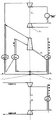
fig. 1 is a schematic thermodynamic system diagram of a combined cycle heat pump apparatus 1 in accordance with the present invention.
Fig. 2 is a schematic thermodynamic system diagram of a 2 nd principle of a combined cycle heat pump apparatus provided in accordance with the present invention.
Fig. 3 is a 3 rd principle thermodynamic system diagram of a combined cycle heat pump apparatus provided in accordance with the present invention.
Fig. 4 is a diagram of a 4 th principle thermodynamic system of a combined cycle heat pump apparatus provided in accordance with the present invention.
Fig. 5 is a diagram of a 5 th principle thermodynamic system of a combined cycle heat pump apparatus provided in accordance with the present invention.
Fig. 6 is a 6 th principle thermodynamic system diagram of a combined cycle heat pump apparatus provided in accordance with the present invention.
Fig. 7 is a 7 th principle thermodynamic system diagram of a combined cycle heat pump apparatus provided in accordance with the present invention.
Fig. 8 is a diagram of an 8 th principle thermodynamic system of a combined cycle heat pump apparatus provided in accordance with the present invention.
Fig. 9 is a diagram of a 9 th principal thermodynamic system of a combined cycle heat pump apparatus provided in accordance with the present invention.
Fig. 10 is a diagram of a 10 th principal thermodynamic system of a combined cycle heat pump apparatus provided in accordance with the present invention.
Fig. 11 is a diagram of a principal 11 thermodynamic system of a combined cycle heat pump apparatus according to the present invention.
Fig. 12 is a 12 th principle thermodynamic system diagram of a combined cycle heat pump apparatus provided in accordance with the present invention.
Fig. 13 is a 13 th principal thermodynamic system diagram of a combined cycle heat pump apparatus provided in accordance with the present invention.
In the figure, 1-compressor, 2-gas turbine, 3-combustion chamber, 4-expander, 5-second expander, 6-circulating pump, 7-second circulating pump, 8-heat supplier, 9-low temperature evaporator, 10-medium temperature evaporator, 11-second compressor, 12-third expander, 13-second heat supplier, 14-low temperature heat regenerator, 15-low temperature heat exchanger, 16-throttle valve, 17-evaporator, 18-heat regenerator, 19-second heat regenerator, 20-third circulating pump, 21-fourth circulating pump, 22-preheater, 23-second preheater, 24-intermediate reheater, 25-third heat supplier, 26-high temperature regenerator.
The specific implementation mode is as follows:
it is to be noted that, in the description of the structure and the flow, the repetition is not necessary; obvious flow is not described. The invention is described in detail below with reference to the figures and examples.
The combined cycle heat pump apparatus shown in fig. 1 is realized by:
(1) structurally, the system mainly comprises a compressor, a gas turbine, a combustion chamber, an expander, a second expander, a circulating pump, a second circulating pump, a heat supply device, a low-temperature evaporator, a medium-temperature evaporator, a second compressor, a third expander and a second heat supply device; the heat supplier 8 is provided with a condensate pipeline which is communicated with the low-temperature evaporator 9 through the circulating pump 6, the low-temperature evaporator 9 is also provided with a steam channel which is communicated with the expander 4, and the expander 4 is also provided with a steam channel which is communicated with the heat supplier 8; the heat supplier 8 is also provided with a condensate pipeline which is communicated with the medium temperature evaporator 10 through a second circulating pump 7, then the medium temperature evaporator 10 is further provided with a steam channel which is communicated with the second expander 5, and the second expander 5 is also provided with a steam channel which is communicated with the heat supplier 8; an air channel is arranged outside and communicated with the compressor 1, the compressor 1 is also provided with an air channel which is communicated with the combustion chamber 3, a fuel channel is also arranged outside and communicated with the combustion chamber 3, the combustion chamber 3 is also provided with a gas channel which is communicated with the gas turbine 2, and the gas turbine 2 is also provided with a gas channel which is communicated with the outside through the medium-temperature evaporator 10 and the low-temperature evaporator 9; a low-temperature heat medium channel is arranged outside and communicated with the second compressor 11, the second compressor 11 is also provided with a low-temperature heat medium channel which is communicated with the third expander 12 through the second heat supplier 13, and the third expander 12 is also provided with a low-temperature heat medium channel which is communicated with the outside; the heat supply device 8 and the second heat supply device 13 are also respectively communicated with the outside through heated medium channels, and the gas turbine 2, the expander 4, the second expander 5 and the third expander 12 are connected with the compressor 1 and the second compressor 11 and transmit power.
(2) In the process, external air flows through the compressor 1, is boosted and heated, then enters the combustion chamber 3, external fuel enters the combustion chamber 3, is mixed with the air and is combusted into high-temperature fuel gas, the fuel gas flows through the gas turbine 2, is reduced in pressure and does work, flows through the medium-temperature evaporator 10 and the low-temperature evaporator 9, gradually releases heat, and then is externally discharged; the condensate of the heat supply device 8 is divided into two paths, wherein the first path is pressurized by the circulating pump 6 and enters the low-temperature evaporator 9 to absorb heat and vaporize, and the second path is pressurized by the second circulating pump 7 and enters the medium-temperature evaporator 10 to absorb heat and vaporize; the steam generated by the low-temperature evaporator 9 enters the expansion machine 4 to reduce the pressure and do work, and then enters the heat supply device 8 to release heat and condense; the steam generated by the medium temperature evaporator 10 flows through the second expander 5 to reduce the pressure and do work, and then enters the heat supply device 8 to release heat and condense; the external low-temperature heat medium enters the second compressor 11 to be boosted and heated, flows through the second heat supply device 13 to release heat, flows through the third expansion machine 12 to be decompressed and work, and is discharged outwards; the fuel is combusted in the combustion chamber 3 to provide a driving heat load, the medium-temperature heat load is taken away by the heated medium through the heat supply device 8 and the second heat supply device 13, the low-temperature heat load is provided by the low-temperature heat medium through an inlet and outlet flow path, and the work output by the gas turbine 2, the expansion machine 4, the second expansion machine 5 and the third expansion machine 12 is provided for the compressor 1 and the second compressor 11 as power, so that the combined cycle heat pump device is formed.
The combined cycle heat pump apparatus shown in fig. 2 is realized by:
(1) structurally, the system mainly comprises a compressor, a gas turbine, a combustion chamber, an expander, a second expander, a circulating pump, a second circulating pump, a heat supply device, a low-temperature evaporator, a medium-temperature evaporator, a second compressor, a third expander, a second heat supply device and a low-temperature heat regenerator; the heat supplier 8 is provided with a condensate pipeline which is communicated with the low-temperature evaporator 9 through the circulating pump 6, the low-temperature evaporator 9 is also provided with a steam channel which is communicated with the expander 4, and the expander 4 is also provided with a steam channel which is communicated with the heat supplier 8; the heat supplier 8 is also provided with a condensate pipeline which is communicated with the medium temperature evaporator 10 through a second circulating pump 7, then the medium temperature evaporator 10 is further provided with a steam channel which is communicated with the second expander 5, and the second expander 5 is also provided with a steam channel which is communicated with the heat supplier 8; an air channel is arranged outside and communicated with the compressor 1, the compressor 1 is also provided with an air channel which is communicated with the combustion chamber 3, a fuel channel is also arranged outside and communicated with the combustion chamber 3, the combustion chamber 3 is also provided with a gas channel which is communicated with the gas turbine 2, and the gas turbine 2 is also provided with a gas channel which is communicated with the outside through the medium-temperature evaporator 10 and the low-temperature evaporator 9; a low-temperature heat medium channel is arranged outside and communicated with the second compressor 11 through a low-temperature heat regenerator 14, the second compressor 11 is also provided with a low-temperature heat medium channel which is communicated with a third expander 12 through a second heat supplier 13 and the low-temperature heat regenerator 14, and the third expander 12 is also provided with a low-temperature heat medium channel which is communicated with the outside; the heat supply device 8 and the second heat supply device 13 are also respectively communicated with the outside through heated medium channels, and the gas turbine 2, the expander 4, the second expander 5 and the third expander 12 are connected with the compressor 1 and the second compressor 11 and transmit power.
(2) In the process, external air flows through the compressor 1, is boosted and heated, then enters the combustion chamber 3, external fuel enters the combustion chamber 3, is mixed with the air and is combusted into high-temperature fuel gas, the fuel gas flows through the gas turbine 2, is reduced in pressure and does work, flows through the medium-temperature evaporator 10 and the low-temperature evaporator 9, gradually releases heat, and then is externally discharged; the condensate of the heater 8 is divided into two paths, wherein the first path is pressurized by the circulating pump 6 and enters the low-temperature evaporator 9 to absorb heat and vaporize, and the second path is pressurized by the second circulating pump 7 and enters the medium-temperature evaporator 10 to absorb heat and vaporize; the steam generated by the low-temperature evaporator 9 enters the expansion machine 4 to reduce the pressure and do work, and then enters the heat supply device 8 to release heat and condense; the steam generated by the medium temperature evaporator 10 flows through the second expander 5 to reduce the pressure and do work, and then enters the heat supply device 8 to release heat and condense; the external low-temperature heat medium flows through the low-temperature heat regenerator 14 to absorb heat, flows through the second compressor 11 to increase the pressure and the temperature, flows through the second heat supplier 13 and the low-temperature heat regenerator 14 to gradually release heat, flows through the third expander 12 to reduce the pressure and do work, and is externally discharged; the fuel is combusted in the combustion chamber 3 to provide a driving heat load, the medium-temperature heat load is taken away by the heated medium through the heat supply device 8 and the second heat supply device 13, the low-temperature heat load is provided by the low-temperature heat medium through an inlet and outlet flow path, and the work output by the gas turbine 2, the expansion machine 4, the second expansion machine 5 and the third expansion machine 12 is provided for the compressor 1 and the second compressor 11 as power, so that the combined cycle heat pump device is formed.
The combined cycle heat pump apparatus shown in fig. 3 is realized by:
(1) structurally, the system mainly comprises a compressor, a gas turbine, a combustion chamber, an expander, a second expander, a circulating pump, a second circulating pump, a heat supply device, a low-temperature evaporator, a medium-temperature evaporator, a second compressor, a third expander, a second heat supply device and a low-temperature heat exchanger; the heat supplier 8 is provided with a condensate pipeline which is communicated with the low-temperature evaporator 9 through the circulating pump 6, the low-temperature evaporator 9 is also provided with a steam channel which is communicated with the expander 4, and the expander 4 is also provided with a steam channel which is communicated with the heat supplier 8; the heat supplier 8 is also provided with a condensate pipeline which is communicated with the medium-temperature evaporator 10 through a second circulating pump 7, then the medium-temperature evaporator 10 is also provided with a steam channel which is communicated with the second expander 5, and the second expander 5 is also provided with a steam channel which is communicated with the heat supplier 8; an air channel is arranged outside and communicated with the compressor 1, the compressor 1 is also provided with an air channel which is communicated with the combustion chamber 3, a fuel channel is also arranged outside and communicated with the combustion chamber 3, the combustion chamber 3 is also provided with a gas channel which is communicated with the gas turbine 2, and the gas turbine 2 is also provided with a gas channel which is communicated with the outside through the medium-temperature evaporator 10 and the low-temperature evaporator 9; the second compressor 11 is provided with a circulating medium channel which is communicated with the third expander 12 through the second heat supplier 13, and the third expander 12 is also provided with a circulating medium channel which is communicated with the second compressor 11 through the low-temperature heat exchanger 15; the heat supply device 8 and the second heat supply device 13 are respectively communicated with the outside through heated medium channels, the low-temperature heat exchanger 15 is also communicated with the outside through a low-temperature heat medium channel, and the gas turbine 2, the expander 4, the second expander 5 and the third expander 12 are connected with the compressor 1 and the second compressor 11 and transmit power.
(2) In the process, external air flows through the compressor 1, is boosted and heated, then enters the combustion chamber 3, external fuel enters the combustion chamber 3, is mixed with the air and is combusted into high-temperature fuel gas, the fuel gas flows through the gas turbine 2, is reduced in pressure and does work, flows through the medium-temperature evaporator 10 and the low-temperature evaporator 9, gradually releases heat, and then is externally discharged; the condensate of the heater 8 is divided into two paths, wherein the first path is pressurized by the circulating pump 6 and enters the low-temperature evaporator 9 to absorb heat and vaporize, and the second path is pressurized by the second circulating pump 7 and enters the medium-temperature evaporator 10 to absorb heat and vaporize; the steam generated by the low-temperature evaporator 9 enters the expansion machine 4 to reduce the pressure and do work, and then enters the heat supply device 8 to release heat and condense; the steam generated by the medium temperature evaporator 10 flows through the second expander 5 to reduce the pressure and do work, and then enters the heat supply device 8 to release heat and condense; the circulating medium discharged from the second compressor 11 flows through the second heat supply device 13 and releases heat, flows through the third expansion machine 12 to reduce pressure and do work, flows through the low-temperature heat exchanger 15 and absorbs heat, and then enters the second compressor 11 to increase pressure and temperature; the fuel is combusted in the combustion chamber 3 to provide driving heat load, the medium temperature heat load is taken away by the heated medium through the heat supplier 8 and the second heat supplier 13, the low temperature heat load is provided by the low temperature heat exchanger 15, the work output by the gas turbine 2, the expander 4, the second expander 5 and the third expander 12 is provided for the compressor 1 and the second compressor 11 as power, and the combined cycle heat pump device is formed.
The combined cycle heat pump apparatus shown in fig. 4 is realized by:
(1) structurally, the system mainly comprises a compressor, a gas turbine, a combustion chamber, an expander, a second expander, a circulating pump, a second circulating pump, a heat supply device, a low-temperature evaporator, a medium-temperature evaporator, a second compressor, a third expander, a second heat supply device, a low-temperature heat regenerator and a low-temperature heat exchanger; the heat supplier 8 is provided with a condensate pipeline which is communicated with the low-temperature evaporator 9 through the circulating pump 6, the low-temperature evaporator 9 is also provided with a steam channel which is communicated with the expander 4, and the expander 4 is also provided with a steam channel which is communicated with the heat supplier 8; the heat supplier 8 is also provided with a condensate pipeline which is communicated with the medium temperature evaporator 10 through a second circulating pump 7, then the medium temperature evaporator 10 is further provided with a steam channel which is communicated with the second expander 5, and the second expander 5 is also provided with a steam channel which is communicated with the heat supplier 8; an air channel is arranged outside and communicated with the compressor 1, the compressor 1 is also provided with an air channel which is communicated with the combustion chamber 3, a fuel channel is also arranged outside and communicated with the combustion chamber 3, the combustion chamber 3 is also provided with a gas channel which is communicated with the gas turbine 2, and the gas turbine 2 is also provided with a gas channel which is communicated with the outside through the medium-temperature evaporator 10 and the low-temperature evaporator 9; the second compressor 11 is provided with a circulating medium channel which is communicated with the third expander 12 through the second heat supplier 13 and the low-temperature regenerator 14, and the third expander 12 is also provided with a circulating medium channel which is communicated with the second compressor 11 through the low-temperature heat exchanger 15 and the low-temperature regenerator 14; the heat supply device 8 and the second heat supply device 13 are respectively communicated with the outside through heated medium channels, the low-temperature heat exchanger 15 is also communicated with the outside through a low-temperature heat medium channel, and the gas turbine 2, the expander 4, the second expander 5 and the third expander 12 are connected with the compressor 1 and the second compressor 11 and transmit power.
(2) In the process, external air flows through the compressor 1, is boosted and heated, then enters the combustion chamber 3, external fuel enters the combustion chamber 3, is mixed with the air and is combusted into high-temperature fuel gas, the fuel gas flows through the gas turbine 2, is reduced in pressure and does work, flows through the medium-temperature evaporator 10 and the low-temperature evaporator 9, gradually releases heat, and then is externally discharged; the condensate of the heater 8 is divided into two paths, wherein the first path is pressurized by the circulating pump 6 and enters the low-temperature evaporator 9 to absorb heat and vaporize, and the second path is pressurized by the second circulating pump 7 and enters the medium-temperature evaporator 10 to absorb heat and vaporize; the steam generated by the low-temperature evaporator 9 enters the expander 4 to reduce pressure and do work, and then enters the heat supplier 8 to release heat and condense; the steam generated by the medium temperature evaporator 10 flows through the second expander 5 to reduce the pressure and do work, and then enters the heat supply device 8 to release heat and condense; the circulating medium discharged from the second compressor 11 flows through the second heat supply device 13 and the low-temperature heat regenerator 14 and gradually releases heat, flows through the third expansion machine 12 to reduce pressure and do work, flows through the low-temperature heat exchanger 15 and the low-temperature heat regenerator 14 and gradually absorbs heat, and then enters the second compressor 11 to increase pressure and temperature; the fuel is combusted in the combustion chamber 3 to provide driving heat load, the medium temperature heat load is taken away by the heated medium through the heat supplier 8 and the second heat supplier 13, the low temperature heat load is provided by the low temperature heat exchanger 15, the work output by the gas turbine 2, the expander 4, the second expander 5 and the third expander 12 is provided for the compressor 1 and the second compressor 11 as power, and the combined cycle heat pump device is formed.
The combined cycle heat pump apparatus shown in fig. 5 is realized by:
(1) structurally, the system mainly comprises a compressor, a gas turbine, a combustion chamber, an expander, a second expander, a circulating pump, a second circulating pump, a heat supply device, a low-temperature evaporator, a medium-temperature evaporator, a second compressor, a second heat supply device, a throttle valve and an evaporator; the heat supplier 8 is provided with a condensate pipeline which is communicated with the low-temperature evaporator 9 through the circulating pump 6, the low-temperature evaporator 9 is also provided with a steam channel which is communicated with the expander 4, and the expander 4 is also provided with a steam channel which is communicated with the heat supplier 8; the heat supplier 8 is also provided with a condensate pipeline which is communicated with the medium-temperature evaporator 10 through a second circulating pump 7, then the medium-temperature evaporator 10 is also provided with a steam channel which is communicated with the second expander 5, and the second expander 5 is also provided with a steam channel which is communicated with the heat supplier 8; an air channel is arranged outside and communicated with the compressor 1, the compressor 1 is also provided with an air channel which is communicated with the combustion chamber 3, a fuel channel is also arranged outside and communicated with the combustion chamber 3, the combustion chamber 3 is also provided with a gas channel which is communicated with the gas turbine 2, and the gas turbine 2 is also provided with a gas channel which is communicated with the outside through the medium-temperature evaporator 10 and the low-temperature evaporator 9; the second compressor 11 is provided with a circulating medium channel which is communicated with the second heat supplier 13, the second heat supplier 13 is also provided with a circulating medium channel which is communicated with the evaporator 17 through a throttle valve 16, and the evaporator 17 is also provided with a circulating medium channel which is communicated with the second compressor 11; the heat supply device 8 and the second heat supply device 13 are respectively communicated with the outside through heated medium channels, the medium temperature evaporator 10 is also communicated with the outside through a heat source medium channel, the evaporator 17 is also communicated with the outside through a low temperature medium channel, and the gas turbine 2, the expander 4 and the second expander 5 are connected with the compressor 1 and the second compressor 11 and transmit power.
(2) In the process, external air flows through the compressor 1, is boosted and heated, then enters the combustion chamber 3, external fuel enters the combustion chamber 3, is mixed with the air and is combusted into high-temperature fuel gas, the fuel gas flows through the gas turbine 2, is reduced in pressure and does work, flows through the medium-temperature evaporator 10 and the low-temperature evaporator 9, gradually releases heat, and then is externally discharged; the condensate of the heater 8 is divided into two paths, wherein the first path is pressurized by the circulating pump 6 and enters the low-temperature evaporator 9 to absorb heat and vaporize, and the second path is pressurized by the second circulating pump 7 and enters the medium-temperature evaporator 10 to absorb heat and vaporize; the steam generated by the low-temperature evaporator 9 enters the expansion machine 4 to reduce the pressure and do work, and then enters the heat supply device 8 to release heat and condense; the steam generated by the medium temperature evaporator 10 flows through the second expander 5 to reduce the pressure and do work, and then enters the heat supply device 8 to release heat and condense; the circulating medium discharged by the second compressor 11 enters the second heat supply device 13 to release heat and condense, the condensate flows through the throttle valve 16 to be throttled and decompressed and then enters the evaporator 17 to absorb heat to form steam, and the circulating medium discharged by the evaporator 17 enters the second compressor 11 to be boosted and heated; the fuel is combusted in the combustion chamber 3 to provide driving heat load, the heat source medium provides driving heat load through the medium-temperature evaporator 10, the medium to be heated takes the medium-temperature heat load through the heat supply device 8 and the second heat supply device 13, the low-temperature heat load is provided through the evaporator 17, the work output by the gas turbine 2, the expansion machine 4 and the second expansion machine 5 is provided for the compressor 1 and the second compressor 11 as power, and the combined cycle heat pump device is formed.
The combined cycle heat pump apparatus shown in fig. 6 is realized by:
(1) structurally, in the combined cycle heat pump device shown in fig. 1, a heat regenerator, a second heat regenerator, a third circulating pump and a fourth circulating pump are added, a condensate pipeline of a heat supplier 8 is communicated with a low-temperature evaporator 9 through a circulating pump 6 and is adjusted to be communicated with the heat regenerator 18 through the circulating pump 6, a steam extraction channel is additionally arranged on an expander 4 and is communicated with the heat regenerator 18, and the heat regenerator 18 is further communicated with the low-temperature evaporator 9 through a condensate pipeline through a third circulating pump 20; a condensing liquid pipeline of the heat supply device 8 is communicated with the medium temperature evaporator 10 through the second circulating pump 7, the condition that the condensing liquid pipeline of the heat supply device 8 is communicated with the second heat regenerator 19 through the second circulating pump 7 is adjusted, the second expansion machine 5 is additionally provided with a steam extraction channel which is communicated with the second heat regenerator 19, and the second heat regenerator 19 is communicated with the medium temperature evaporator 10 through a fourth circulating pump 21.
(2) In the process, compared with the combined cycle heat pump device shown in fig. 1, the difference lies in that a first path of condensate of the heat supplier 8 is pressurized by the circulating pump 6 and enters the heat regenerator 18, the extracted steam of the expander 4 enters the heat regenerator 18 to be mixed with the condensate and then releases heat for condensation, and the condensate of the heat regenerator 18 is pressurized by the third circulating pump 20 and enters the low-temperature evaporator 9 to absorb heat and vaporize; the second path of condensate is pressurized by a second circulating pump 7 and enters a second heat regenerator 19, the extracted steam of the second expander 5 enters the second heat regenerator 19 to be mixed with the condensate, then the heat is released and the condensate is condensed, and the condensate of the second heat regenerator 19 is pressurized by a fourth circulating pump 21 and then enters a medium temperature evaporator 10 to absorb heat and vaporize; the steam generated by the low-temperature evaporator 9 is provided for the expansion machine 4, the steam enters the expansion machine 4 to complete partial work and then is divided into two paths, the first path enters the heat regenerator 18, and the second path continues to reduce the pressure and work and then enters the heat supplier 8 to release heat and condense; the steam generated by the medium temperature evaporator 10 passes through the second expander 5 to complete partial pressure reduction work and then is divided into two paths, the first path enters the second heat regenerator 19, and the second path enters the heat supplier 8 to release heat and condense after completing the pressure reduction work, so that the combined cycle heat pump device is formed.
The combined cycle heat pump apparatus shown in fig. 7 is realized by:
(1) structurally, in the combined cycle heat pump device shown in fig. 1, a preheater and a second preheater are added, a condensate pipeline of a heat supply device 8 is communicated and adjusted to the heat supply device 8 through a circulating pump 6 and a low-temperature evaporator 9, the condensate pipeline of the heat supply device 8 is communicated with the low-temperature evaporator 9 through the circulating pump 6 and the preheater 22, the heat supply device 8 is communicated and adjusted to the heat supply device 8 through the second circulating pump 7 and a medium-temperature evaporator 10, the condensate pipeline of the heat supply device 8 is communicated with the medium-temperature evaporator 10 through the second circulating pump 7 and the second preheater 23, and the preheater 22 and the second preheater 23 are respectively communicated with a heat source medium channel and the outside.
(2) Compared with the combined cycle heat pump device shown in fig. 1, the difference in the process is that the first path of condensate of the heat supplier 8 is pressurized by the circulating pump 6, flows through the preheater 22 to absorb heat and raise temperature, then enters the low-temperature evaporator 9 to absorb heat and vaporize, the second path of condensate is pressurized by the second circulating pump 7, flows through the second preheater 23 to absorb heat and raise temperature, then enters the medium-temperature evaporator 10 to absorb heat and vaporize, and the combined cycle heat pump device is formed.
The combined cycle heat pump apparatus shown in fig. 8 is realized by:
(1) structurally, in the combined cycle heat pump apparatus shown in fig. 1, a preheater and a second preheater are added, a condensate pipeline of the heat supply device 8 is communicated with the low temperature evaporator 9 through the circulating pump 6, a condensate pipeline of the heat supply device 8 is communicated with the medium temperature evaporator 10 through the second circulating pump 7, the heat supply device 8 is adjusted to be divided into two paths after the condensate pipeline of the heat supply device 8 passes through the circulating pump 6 and the preheater 22, the first path is directly communicated with the low temperature evaporator 9, the second path is communicated with the medium temperature evaporator 10 through the second circulating pump 7 and the second preheater 23, and the preheater 22 and the second preheater 23 are respectively communicated with the outside through heat source medium channels.
(2) Compared with the combined cycle heat pump device shown in fig. 1, the difference in the process is that the condensate of the heat supplier 8 is pressurized by the circulating pump 6 and absorbs heat by flowing through the preheater 22, and then is divided into two paths, wherein the first path directly enters the low-temperature evaporator 9 to absorb heat for vaporization, and the second path is pressurized by the second circulating pump 7 and absorbs heat by flowing through the second preheater 13 to enter the medium-temperature evaporator 10 to absorb heat for vaporization, so that the combined cycle heat pump device is formed.
The combined cycle heat pump apparatus shown in fig. 9 is realized by:
(1) structurally, in the combined cycle heat pump apparatus shown in fig. 1, an intermediate reheater is added, and the intermediate temperature evaporator 10 having a steam passage communicating with the second expander 5 and the second expander 5 having a steam passage communicating with the heat supply unit 8 are adjusted such that the intermediate temperature evaporator 10 having a steam passage communicating with the second expander 5, the second expander 5 having an intermediate reheater steam passage communicating with the second expander 5 via the intermediate reheater 24 and the second expander 5 having a steam passage communicating with the heat supply unit 8, and the intermediate reheater 24 having a heat source medium passage communicating with the outside.
(2) Compared with the combined cycle heat pump device shown in fig. 1, the difference in the process is that the steam output by the intermediate temperature evaporator 10 enters the second expander 5 to reduce the pressure and do work to a certain intermediate pressure, is led out, enters the intermediate reheater 24 through the intermediate reheating steam channel to absorb heat and raise the temperature, then enters the second expander 5 through the intermediate reheating steam channel to continue reducing the pressure and do work, and then enters the heat supplier 8 to release heat and condense, so as to form the combined cycle heat pump device.
The combined cycle heat pump apparatus shown in fig. 10 is realized by:
(1) structurally, in the combined cycle heat pump apparatus shown in fig. 1, a third heat supply device is added, the second expander 5 is adjusted to have a steam passage to communicate with the heat supply device 8, the second expander 5 has a steam passage to communicate with the third heat supply device 25, the heat supply device 8 has a condensate pipeline to communicate with the intermediate temperature evaporator 10 through the second circulation pump 7, the third heat supply device 25 has a condensate pipeline to communicate with the intermediate temperature evaporator 10 through the second circulation pump 7, and the third heat supply device 25 also has a heated medium passage to communicate with the outside.
(2) Compared with the combined cycle heat pump device shown in fig. 1, the difference in the process is that the steam discharged by the second expander 5 enters the third heat supply device 25 to release heat to the heated medium and is condensed, the condensate of the third condenser 25 flows through the second circulating pump 7 to increase the pressure, flows through the medium temperature evaporator 10 to absorb heat and is vaporized, and then flows through the second expander 5 to reduce the pressure and do work, so as to form the combined cycle heat pump device.
The combined cycle heat pump apparatus shown in fig. 11 is realized by:
(1) structurally, in the combined cycle heat pump device shown in fig. 1, a high temperature heat regenerator is added, an air channel of a compressor 1 is communicated with a combustion chamber 3 and adjusted to be communicated with the combustion chamber 3 through the high temperature heat regenerator 26, and a gas channel of a gas turbine 2 is communicated with the outside through a medium temperature evaporator 10 and a low temperature evaporator 9 and adjusted to be communicated with the outside through the high temperature heat regenerator 26, the medium temperature evaporator 10 and the low temperature evaporator 9.
(2) In the process, compared with the combined cycle heat pump device shown in fig. 1, the difference lies in that the air discharged from the compressor 1 enters the combustion chamber 3 after flowing through the high temperature heat regenerator 26 to absorb heat, and the gas discharged from the gas turbine 2 is discharged to the outside after flowing through the high temperature heat regenerator 26, the medium temperature evaporator 10 and the low temperature evaporator 9 to gradually release heat and reduce temperature, so as to form the combined cycle heat pump device.
The combined cycle steam power plant shown in fig. 12 is implemented as follows:
in the combined cycle steam power plant shown in fig. 1, the second expander 5 having a steam passage communicating with the heat supplier 8 is adjusted so that the second expander 5 having a steam passage communicating with the expander 4; the steam entering the second expander 5 completes partial pressure reduction work, then enters the expander 4 to continue pressure reduction work, and then enters the heat supply device 8 to release heat and condense, so as to form the combined cycle heat pump device.
The combined cycle heat pump apparatus shown in fig. 13 is realized by:
(1) structurally, in the combined cycle heat pump apparatus shown in fig. 1, the second expander is eliminated, the steam passage through which the second expander 5 communicates with the heat supply device 8 is eliminated, the medium temperature evaporator 10 having the steam passage communicating with the second expander 5 is adjusted to the medium temperature evaporator 10 having the steam passage communicating with the expander 4, and the low temperature evaporator 9 having the steam passage communicating with the expander 4 is adjusted to the low temperature evaporator 9 communicating with the expander 4 through the intermediate steam inlet passage.
(2) Compared with the combined cycle heat pump device shown in fig. 1, the difference in the flow is that the steam discharged from the medium temperature evaporator 10 flows through the expansion machine 4 to perform decompression work, and then enters the heat supply device 8; the steam discharged from the low-temperature evaporator 9 enters the expander 4 through the middle steam inlet channel to reduce pressure and do work, and then enters the heat supply device 8 to form the combined cycle heat pump device.
The effect that the technology of the invention can realize-the combined cycle heat pump device provided by the invention has the following effects and advantages:
(1) provides a new idea and a new technology for utilizing the temperature difference.
(2) High-efficiency heat supply or cold supply is actively realized, and the cost is reduced.
(3) The intermediate temperature zone is utilized in a grading way, so that the reasonable utilization of temperature difference is realized; reduce the irreversible loss of heat transfer and improve the utilization rate of heat energy.
(4) Multiple working medium circulation, and greatly expanded working parameter range.
(5) Can actively and independently realize cold supply or heat supply, and can actively provide cold and heat cogeneration, heat cogeneration or cold and heat cogeneration at the same time.
(6) The temperature difference can be effectively utilized independently or the heat energy and the mechanical energy can be effectively utilized simultaneously.
(7) Two-end or multi-end heat supply is realized in the flow of the compression heat pump, which is beneficial to improving the performance index and improving the energy utilization rate.
Claims (21)
1. The combined cycle heat pump device mainly comprises a compressor, a gas turbine, a combustion chamber, an expander, a second expander, a circulating pump, a second circulating pump, a heat supply device, a low-temperature evaporator, a medium-temperature evaporator, a second compressor, a third expander and a second heat supply device; the heat supply device (8) is provided with a condensate pipeline which is communicated with the low-temperature evaporator (9) through the circulating pump (6), the low-temperature evaporator (9) is also provided with a steam channel which is communicated with the expander (4), and the expander (4) is also provided with a steam channel which is communicated with the heat supply device (8); the heat supplier (8) is also provided with a condensate pipeline which is communicated with the medium temperature evaporator (10) through a second circulating pump (7), then the medium temperature evaporator (10) is also provided with a steam channel which is communicated with the second expander (5), and the second expander (5) is also provided with a steam channel which is communicated with the heat supplier (8); an air channel is arranged outside and communicated with the compressor (1), the compressor (1) is also provided with an air channel communicated with the combustion chamber (3), a fuel channel is also arranged outside and communicated with the combustion chamber (3), the combustion chamber (3) is also provided with a gas channel communicated with the gas turbine (2), and the gas turbine (2) is also provided with a gas channel communicated with the outside through the medium-temperature evaporator (10) and the low-temperature evaporator (9); a low-temperature heat medium channel is arranged outside and communicated with the second compressor (11), the second compressor (11) is also provided with a low-temperature heat medium channel which is communicated with the third expander (12) through the second heat supply device (13), and the third expander (12) is also provided with a low-temperature heat medium channel which is communicated with the outside; the heat supply device (8) and the second heat supply device (13) are also respectively communicated with the outside through heated medium channels, and the gas turbine (2), the expander (4), the second expander (5) and the third expander (12) are connected with the compressor (1) and the second compressor (11) and transmit power to form a combined cycle heat pump device.
2. The combined cycle heat pump device mainly comprises a compressor, a gas turbine, a combustion chamber, an expander, a second expander, a circulating pump, a second circulating pump, a heat supplier, a low-temperature evaporator, a medium-temperature evaporator, a second compressor, a third expander, a second heat supplier and a low-temperature heat regenerator; the heat supply device (8) is provided with a condensate pipeline which is communicated with the low-temperature evaporator (9) through the circulating pump (6), the low-temperature evaporator (9) is also provided with a steam channel which is communicated with the expander (4), and the expander (4) is also provided with a steam channel which is communicated with the heat supply device (8); the heat supplier (8) is also provided with a condensate pipeline which is communicated with the medium temperature evaporator (10) through a second circulating pump (7), then the medium temperature evaporator (10) is also provided with a steam channel which is communicated with the second expander (5), and the second expander (5) is also provided with a steam channel which is communicated with the heat supplier (8); an air channel is arranged outside and communicated with the compressor (1), the compressor (1) is also provided with an air channel communicated with the combustion chamber (3), a fuel channel is also arranged outside and communicated with the combustion chamber (3), the combustion chamber (3) is also provided with a gas channel communicated with the gas turbine (2), and the gas turbine (2) is also provided with a gas channel communicated with the outside through the medium-temperature evaporator (10) and the low-temperature evaporator (9); a low-temperature heat medium channel is arranged outside and is communicated with a second compressor (11) through a low-temperature heat regenerator (14), the second compressor (11) is also provided with a low-temperature heat medium channel which is communicated with a third expander (12) through a second heat supplier (13) and the low-temperature heat regenerator (14), and the third expander (12) is also provided with a low-temperature heat medium channel which is communicated with the outside; the heat supply device (8) and the second heat supply device (13) are also respectively communicated with the outside through heated medium channels, and the gas turbine (2), the expander (4), the second expander (5) and the third expander (12) are connected with the compressor (1) and the second compressor (11) and transmit power to form a combined cycle heat pump device.
3. The combined cycle heat pump device mainly comprises a compressor, a gas turbine, a combustion chamber, an expander, a second expander, a circulating pump, a second circulating pump, a heat supplier, a low-temperature evaporator, a medium-temperature evaporator, a second compressor, a third expander, a second heat supplier and a low-temperature heat exchanger; the heat supplier (8) is provided with a condensate pipeline which is communicated with the low-temperature evaporator (9) through the circulating pump (6), the low-temperature evaporator (9) is also provided with a steam channel which is communicated with the expander (4), and the expander (4) is also provided with a steam channel which is communicated with the heat supplier (8); the heat supplier (8) is also provided with a condensate pipeline which is communicated with the medium temperature evaporator (10) through a second circulating pump (7), then the medium temperature evaporator (10) is also provided with a steam channel which is communicated with the second expander (5), and the second expander (5) is also provided with a steam channel which is communicated with the heat supplier (8); an air channel is arranged outside and communicated with the compressor (1), the compressor (1) is also provided with an air channel and communicated with the combustion chamber (3), a fuel channel is also arranged outside and communicated with the combustion chamber (3), the combustion chamber (3) is also provided with a gas channel and communicated with the gas turbine (2), and the gas turbine (2) is also provided with a gas channel and communicated with the outside through the medium-temperature evaporator (10) and the low-temperature evaporator (9); the second compressor (11) is provided with a circulating medium channel which is communicated with a third expander (12) through a second heat supply device (13), and the third expander (12) is also provided with a circulating medium channel which is communicated with the second compressor (11) through a low-temperature heat exchanger (15); the heat supply device (8) and the second heat supply device (13) are also respectively communicated with the outside through heated medium channels, the low-temperature heat exchanger (15) is also communicated with the outside through a low-temperature heat medium channel, and the gas turbine (2), the expander (4), the second expander (5) and the third expander (12) are connected with the compressor (1) and the second compressor (11) and transmit power to form the combined cycle heat pump device.
4. The combined cycle heat pump device mainly comprises a compressor, a gas turbine, a combustion chamber, an expander, a second expander, a circulating pump, a second circulating pump, a heat supply device, a low-temperature evaporator, a medium-temperature evaporator, a second compressor, a third expander, a second heat supply device, a low-temperature heat regenerator and a low-temperature heat exchanger; the heat supply device (8) is provided with a condensate pipeline which is communicated with the low-temperature evaporator (9) through the circulating pump (6), the low-temperature evaporator (9) is also provided with a steam channel which is communicated with the expander (4), and the expander (4) is also provided with a steam channel which is communicated with the heat supply device (8); the heat supplier (8) is also provided with a condensate pipeline which is communicated with the medium temperature evaporator (10) through a second circulating pump (7), then the medium temperature evaporator (10) is also provided with a steam channel which is communicated with the second expander (5), and the second expander (5) is also provided with a steam channel which is communicated with the heat supplier (8); an air channel is arranged outside and communicated with the compressor (1), the compressor (1) is also provided with an air channel and communicated with the combustion chamber (3), a fuel channel is also arranged outside and communicated with the combustion chamber (3), the combustion chamber (3) is also provided with a gas channel and communicated with the gas turbine (2), and the gas turbine (2) is also provided with a gas channel and communicated with the outside through the medium-temperature evaporator (10) and the low-temperature evaporator (9); the second compressor (11) is provided with a circulating medium channel which is communicated with a third expander (12) through a second heat supply device (13) and a low-temperature heat regenerator (14), and the third expander (12) is also provided with a circulating medium channel which is communicated with the second compressor (11) through a low-temperature heat exchanger (15) and the low-temperature heat regenerator (14); the heat supply device (8) and the second heat supply device (13) are also respectively communicated with the outside through heated medium channels, the low-temperature heat exchanger (15) is also communicated with the outside through a low-temperature heat medium channel, and the gas turbine (2), the expander (4), the second expander (5) and the third expander (12) are connected with the compressor (1) and the second compressor (11) and transmit power to form the combined cycle heat pump device.
5. The combined cycle heat pump device mainly comprises a compressor, a gas turbine, a combustion chamber, an expander, a second expander, a circulating pump, a second circulating pump, a heat supplier, a low-temperature evaporator, a medium-temperature evaporator, a second compressor, a second heat supplier, a throttle valve and an evaporator; the heat supply device (8) is provided with a condensate pipeline which is communicated with the low-temperature evaporator (9) through the circulating pump (6), the low-temperature evaporator (9) is also provided with a steam channel which is communicated with the expander (4), and the expander (4) is also provided with a steam channel which is communicated with the heat supply device (8); the heat supplier (8) is also provided with a condensate pipeline which is communicated with the medium-temperature evaporator (10) through a second circulating pump (7), then a steam channel of the medium-temperature evaporator (10) is communicated with the second expander (5), and the second expander (5) is also provided with a steam channel which is communicated with the heat supplier (8); an air channel is arranged outside and communicated with the compressor (1), the compressor (1) is also provided with an air channel and communicated with the combustion chamber (3), a fuel channel is also arranged outside and communicated with the combustion chamber (3), the combustion chamber (3) is also provided with a gas channel and communicated with the gas turbine (2), and the gas turbine (2) is also provided with a gas channel and communicated with the outside through the medium-temperature evaporator (10) and the low-temperature evaporator (9); the second compressor (11) is provided with a circulating medium channel which is communicated with the second heat supply device (13), the second heat supply device (13) is also provided with a circulating medium channel which is communicated with the evaporator (17) through a throttle valve (16), and the evaporator (17) is also provided with a circulating medium channel which is communicated with the second compressor (11); the heat supply device (8) and the second heat supply device (13) are also respectively communicated with the outside through heated medium channels, the evaporator (17) is also communicated with the outside through low-temperature heat medium channels, and the gas turbine (2), the expander (4) and the second expander (5) are connected with the compressor (1) and the second compressor (11) and transmit power to form a combined cycle heat pump device.
6. A combined cycle heat pump device is characterized in that a heat regenerator and a third circulating pump are added in any combined cycle heat pump device of claims 1 to 5, a condensing liquid pipeline of a heat supplier (8) is communicated with a low-temperature evaporator (9) through a circulating pump (6) and is adjusted to be communicated with a heat regenerator (18) through the circulating pump (6) and the condensing liquid pipeline of the heat supplier (8), an additional steam extraction channel of an expander (4) or a second expander (5) is communicated with the heat regenerator (18), and the condensing liquid pipeline of the heat regenerator (18) is communicated with the low-temperature evaporator (9) through the third circulating pump (20) to form the combined cycle heat pump device.
7. A combined cycle heat pump device is characterized in that a heat regenerator and a third circulating pump are added in any combined cycle heat pump device of claims 1-5, a condensate pipeline of a heat supplier (8) is communicated with a medium temperature evaporator (10) through a second circulating pump (7) and is adjusted to be communicated with a heat regenerator (18) through the second circulating pump (7) and the condensate pipeline of the heat supplier (8), an expansion machine (4) or a second expansion machine (5) is additionally provided with a steam extraction channel to be communicated with the heat regenerator (18), and the heat regenerator (18) is further communicated with the medium temperature evaporator (10) through the third circulating pump (20) through the condensate pipeline to form the combined cycle heat pump device.
8. A combined cycle heat pump device is characterized in that a heat regenerator, a second heat regenerator, a third circulating pump and a fourth circulating pump are added in any combined cycle heat pump device of claims 1 to 5, a condensing liquid pipeline of a heat supplier (8) is communicated with a low-temperature evaporator (9) through a circulating pump (6) and is adjusted to be communicated with a condensing liquid pipeline of the heat supplier (8) and a heat regenerator (18) through the circulating pump (6), an expansion machine (4) or the second expansion machine (5) is additionally provided with a steam extraction channel to be communicated with the heat regenerator (18), and the condensing liquid pipeline of the heat regenerator (18) is communicated with the low-temperature evaporator (9) through a third circulating pump (20); a heat supply device (8) is provided with a condensate pipeline which is communicated with a medium temperature evaporator (10) through a second circulating pump (7) and adjusted to be that the heat supply device (8) is provided with a condensate pipeline which is communicated with a second heat regenerator (19) through the second circulating pump (7), a steam extraction channel is additionally arranged on an expander (4) or a second expander (5) and is communicated with the second heat regenerator (19), and the second heat regenerator (19) is provided with a condensate pipeline which is communicated with the medium temperature evaporator (10) through a fourth circulating pump (21), so that the combined cycle heat pump device is formed.
9. A combined cycle heat pump device is characterized in that a preheater is added in any combined cycle heat pump device as claimed in claims 1-5, a condensate pipeline of a heat supply device (8) is communicated with a low-temperature evaporator (9) through a circulating pump (6) and is adjusted to be communicated with the low-temperature evaporator (9) through the circulating pump (6) and the preheater (22), a condensate pipeline of the heat supply device (8) is communicated with the low-temperature evaporator (9), and the preheater (22) is also communicated with the outside through a heat source medium channel to form the combined cycle heat pump device.
10. A combined cycle heat pump device is characterized in that a preheater is added in any combined cycle heat pump device in claims 1-5, a condensate pipeline of a heat supply device (8) is communicated with a medium temperature evaporator (10) through a second circulating pump (7) and is adjusted to be communicated with the medium temperature evaporator (10) through the second circulating pump (7) and the preheater (22), a condensate pipeline of the heat supply device (8) is communicated with the medium temperature evaporator (10), and the preheater (22) is also communicated with the outside through a heat source medium channel to form the combined cycle heat pump device.
11. A combined cycle heat pump device is characterized in that a preheater and a second preheater are added in any combined cycle heat pump device of claims 1-5, a condensed fluid pipeline of a heat supplier (8) is communicated with a low-temperature evaporator (9) through a circulating pump (6) and adjusted to be communicated with the low-temperature evaporator (9) through the circulating pump (6) and the preheater (22) in the heat supplier (8), the condensed fluid pipeline of the heat supplier (8) is communicated with a medium-temperature evaporator (10) through the second circulating pump (7) and adjusted to be communicated with the heat supplier (8), the condensed fluid pipeline of the heat supplier (8) is communicated with the medium-temperature evaporator (10) through the second circulating pump (7) and the second preheater (23), and the preheater (22) and the second preheater (23) are respectively communicated with the outside through heat source medium channels to form the combined cycle heat pump device.
12. A combined cycle heat pump device is characterized in that a preheater and a second preheater are added in any combined cycle heat pump device of claims 1-5, a heat supplier (8) is provided with a condensate pipeline which is communicated with a low temperature evaporator (9) through a circulating pump (6), the heat supplier (8) is provided with a condensate pipeline which is communicated with a medium temperature evaporator (10) through a second circulating pump (7), the heat supplier (8) is adjusted to be provided with a condensate pipeline which is divided into two paths after passing through the circulating pump (6) and the preheater (22), the first path is directly communicated with the low temperature evaporator (9), the second path is communicated with the medium temperature evaporator (10) through the second circulating pump (7) and the second preheater (23), and the preheater (22) and the second preheater (23) are respectively provided with a heat source medium channel which is communicated with the outside to form the combined cycle heat pump device.
13. A combined cycle heat pump device, in any combined cycle heat pump device of claims 1-12, an intermediate reheater is added, a medium temperature evaporator (10) is provided with a steam passage communicated with a second expander (5) and the second expander (5) is provided with a steam passage communicated with a heat supply device (8), the medium temperature evaporator (10) is provided with a steam passage communicated with the second expander (5), the second expander (5) and an intermediate reheater steam passage are communicated with the second expander (5) through the intermediate reheater (24), the second expander (5) and a steam passage are communicated with the heat supply device (8), and the intermediate reheater (24) and a heat source medium passage are communicated with the outside to form the combined cycle heat pump device.
14. A combined cycle heat pump device is characterized in that a third heat supply device is added in any combined cycle heat pump device of claims 1-5, a second expander (5) is communicated with the heat supply device (8) through a steam channel, the second expander (5) is communicated with the third heat supply device (25) through a steam channel, the heat supply device (8) is communicated with a medium temperature evaporator (10) through a second circulating pump (7) through a condensate pipeline, the third heat supply device (25) is communicated with the medium temperature evaporator (10) through the second circulating pump (7) through a condensate pipeline, and the third heat supply device (25) is also communicated with the outside through a heated medium channel to form the combined cycle heat pump device.
15. A combined cycle heat pump device is characterized in that a high-temperature heat regenerator is added in any combined cycle heat pump device of claims 1-14, an air channel of a compressor (1) is communicated with a combustion chamber (3) and adjusted to be communicated with the combustion chamber (3) through the high-temperature heat regenerator (26), a gas channel of a gas turbine (2) is communicated with the outside through a medium-temperature evaporator (10) and a low-temperature evaporator (9) and adjusted to be communicated with the outside through the high-temperature heat regenerator (26), the medium-temperature evaporator (10) and the low-temperature evaporator (9), and the gas channel of the gas turbine (2) is communicated with the outside through the high-temperature heat regenerator (26), the medium-temperature evaporator (10) and the low-temperature evaporator (9), so that the combined cycle heat pump device is formed.
16. A combined cycle heat pump device, in any one of the combined cycle heat pump devices of claims 1 to 13 and 15, the second expander (5) is provided with a steam channel to communicate with the heat supplier (8) and is adjusted to be provided with a steam channel to communicate with the expander (4) so as to form the combined cycle heat pump device.
17. A combined cycle heat pump device, in any combined cycle heat pump device of claims 1-13, 15, a second expander is cancelled, a steam channel of the second expander (5) communicated with a heat supply device (8) is cancelled, the communication of the medium temperature evaporator (10) with the steam channel and the second expander (5) is adjusted to the communication of the medium temperature evaporator (10) with the steam channel and the expander (4), the communication of the low temperature evaporator (9) with the expander (4) is adjusted to the communication of the low temperature evaporator (9) with the expander (4) through a middle steam inlet channel, and the combined cycle heat pump device is formed.
18. A combined cycle heat pump device, in any combined cycle heat pump device of claims 1-17, a heat source medium channel is additionally arranged on the low temperature evaporator (9) or the medium temperature evaporator (10) to be communicated with the outside, thereby forming the combined cycle heat pump device.
19. A combined cycle heat pump device is characterized in that in any combined cycle heat pump device of claims 1-17, a heat source medium channel is respectively added on the low temperature evaporator (9) and the medium temperature evaporator (10) to be communicated with the outside to form the combined cycle heat pump device.
20. The combined cycle heat pump device is characterized in that a power machine is added in any combined cycle heat pump device of claims 1-19, the power machine is connected with the second compressor (11) and provides power for the second compressor (11), and the combined cycle heat pump device driven by additional external power is formed.
21. The combined cycle heat pump device is characterized in that a working machine is added in any combined cycle heat pump device of claims 1-19, and a gas turbine (2) is connected with and provides power for the working machine to form the combined cycle heat pump device which additionally provides power load to the outside.
Applications Claiming Priority (2)
| Application Number | Priority Date | Filing Date | Title |
|---|---|---|---|
| CN201810545986 | 2018-05-20 | ||
| CN2018105459869 | 2018-05-20 |
Publications (2)
| Publication Number | Publication Date |
|---|---|
| CN110542242A CN110542242A (en) | 2019-12-06 |
| CN110542242B true CN110542242B (en) | 2022-09-23 |
Family
ID=68709520
Family Applications (1)
| Application Number | Title | Priority Date | Filing Date |
|---|---|---|---|
| CN201910455857.5A Active CN110542242B (en) | 2018-05-20 | 2019-05-17 | Combined cycle heat pump device |
Country Status (1)
| Country | Link |
|---|---|
| CN (1) | CN110542242B (en) |
Families Citing this family (1)
| Publication number | Priority date | Publication date | Assignee | Title |
|---|---|---|---|---|
| WO2022148329A1 (en) * | 2021-01-11 | 2022-07-14 | 李华玉 | Dual-fuel gas-steam combined cycle power equipment |
Citations (9)
| Publication number | Priority date | Publication date | Assignee | Title |
|---|---|---|---|---|
| DE102010061525A1 (en) * | 2010-12-23 | 2012-06-28 | Benteler Automobiltechnik Gmbh | Device for inter-cooling of turbocharged internal combustion engine, has compressor of compression refrigerating machine, which stands in work connection with turbine |
| DE102015003546A1 (en) * | 2015-03-19 | 2015-08-20 | Daimler Ag | Air conditioning device for a vehicle |
| CN104879177A (en) * | 2015-04-21 | 2015-09-02 | 同济大学 | Organic Rankin cycle and heat pump cycle coupling system |
| CN106225281A (en) * | 2015-12-30 | 2016-12-14 | 李华玉 | First kind thermal drivers compression heat pump |
| CN106352578A (en) * | 2015-12-30 | 2017-01-25 | 李华玉 | First-type thermally driven compression heat pump |
| CN106403370A (en) * | 2015-12-30 | 2017-02-15 | 李华玉 | First-type thermally-driven compression heat pump |
| CN106440511A (en) * | 2015-12-30 | 2017-02-22 | 李华玉 | First-kind thermally-driven compression type heat pump |
| CN106969401A (en) * | 2017-05-17 | 2017-07-21 | 中能服能源科技股份有限公司 | A kind of new central heating system of air source heat pump and gas fired-boiler |
| CN107605554A (en) * | 2015-11-27 | 2018-01-19 | 张玉良 | Self-cooled thermal circulation method |
-
2019
- 2019-05-17 CN CN201910455857.5A patent/CN110542242B/en active Active
Patent Citations (9)
| Publication number | Priority date | Publication date | Assignee | Title |
|---|---|---|---|---|
| DE102010061525A1 (en) * | 2010-12-23 | 2012-06-28 | Benteler Automobiltechnik Gmbh | Device for inter-cooling of turbocharged internal combustion engine, has compressor of compression refrigerating machine, which stands in work connection with turbine |
| DE102015003546A1 (en) * | 2015-03-19 | 2015-08-20 | Daimler Ag | Air conditioning device for a vehicle |
| CN104879177A (en) * | 2015-04-21 | 2015-09-02 | 同济大学 | Organic Rankin cycle and heat pump cycle coupling system |
| CN107605554A (en) * | 2015-11-27 | 2018-01-19 | 张玉良 | Self-cooled thermal circulation method |
| CN106225281A (en) * | 2015-12-30 | 2016-12-14 | 李华玉 | First kind thermal drivers compression heat pump |
| CN106352578A (en) * | 2015-12-30 | 2017-01-25 | 李华玉 | First-type thermally driven compression heat pump |
| CN106403370A (en) * | 2015-12-30 | 2017-02-15 | 李华玉 | First-type thermally-driven compression heat pump |
| CN106440511A (en) * | 2015-12-30 | 2017-02-22 | 李华玉 | First-kind thermally-driven compression type heat pump |
| CN106969401A (en) * | 2017-05-17 | 2017-07-21 | 中能服能源科技股份有限公司 | A kind of new central heating system of air source heat pump and gas fired-boiler |
Also Published As
| Publication number | Publication date |
|---|---|
| CN110542242A (en) | 2019-12-06 |
Similar Documents
| Publication | Publication Date | Title |
|---|---|---|
| CN108119195B (en) | Combined cycle power plant | |
| CN108662809B (en) | Double-working medium combined cycle compression heat pump | |
| CN110530058B (en) | Combined cycle heat pump device | |
| WO2020224284A1 (en) | Combined cycle power plant | |
| CN110542242B (en) | Combined cycle heat pump device | |
| WO2021068431A1 (en) | Single-working-medium combined cycle heat pump device | |
| CN112344586A (en) | Single-working medium combined cycle heat pump device | |
| CN112344583A (en) | Single-working medium combined cycle heat pump device | |
| CN110953026A (en) | Combined cycle power plant | |
| WO2021068429A1 (en) | Single-working-medium combined cycle heat pump device | |
| WO2021072991A1 (en) | Single-working medium combined cycle heat pump device | |
| WO2022105044A1 (en) | First-type thermally-driven combined cycle heat pump apparatus | |
| WO2021072994A1 (en) | Single working medium combined cycle heat pump device | |
| WO2021072989A1 (en) | Single-working medium combined cycle heat pump device | |
| WO2021068428A1 (en) | Single-working-medium combined cycle heat pump device | |
| WO2021072993A1 (en) | Single-working-medium combined cycle heat pump device | |
| WO2021244028A1 (en) | First-type thermally-driven combined cycle heat pump device | |
| WO2021072992A1 (en) | Single working medium combined circulation heat pump device | |
| WO2021072990A1 (en) | Single-working medium combined cycle heat pump device | |
| CN113685241A (en) | Internal combustion engine type combined cycle power plant | |
| CN113217126A (en) | Internal combustion engine type combined cycle power plant | |
| CN110985150A (en) | Combined cycle power plant | |
| CN115387870A (en) | Double-heat source combined cycle steam power device | |
| CN112344585A (en) | Single-working medium combined cycle heat pump device | |
| CN112344584A (en) | Single-working medium combined cycle heat pump device |
Legal Events
| Date | Code | Title | Description |
|---|---|---|---|
| PB01 | Publication | ||
| PB01 | Publication | ||
| SE01 | Entry into force of request for substantive examination | ||
| SE01 | Entry into force of request for substantive examination | ||
| GR01 | Patent grant | ||
| GR01 | Patent grant |