CN110509941B - Seat for passenger compartment of rail transit vehicle - Google Patents
Seat for passenger compartment of rail transit vehicle Download PDFInfo
- Publication number
- CN110509941B CN110509941B CN201910877672.3A CN201910877672A CN110509941B CN 110509941 B CN110509941 B CN 110509941B CN 201910877672 A CN201910877672 A CN 201910877672A CN 110509941 B CN110509941 B CN 110509941B
- Authority
- CN
- China
- Prior art keywords
- seat
- bracket
- rotating arm
- passenger compartment
- rail transit
- Prior art date
- Legal status (The legal status is an assumption and is not a legal conclusion. Google has not performed a legal analysis and makes no representation as to the accuracy of the status listed.)
- Active
Links
Images
Classifications
-
- B—PERFORMING OPERATIONS; TRANSPORTING
- B61—RAILWAYS
- B61D—BODY DETAILS OR KINDS OF RAILWAY VEHICLES
- B61D33/00—Seats
- B61D33/0007—Details; Accessories
Landscapes
- Engineering & Computer Science (AREA)
- Mechanical Engineering (AREA)
- Fittings On The Vehicle Exterior For Carrying Loads, And Devices For Holding Or Mounting Articles (AREA)
Abstract
Description
技术领域technical field
本发明涉及轨道车辆配套设施领域,具体为一种轨道交通车辆客厢用座椅。The invention relates to the field of rail vehicle supporting facilities, in particular to a passenger compartment seat for rail transit vehicles.
背景技术Background technique
随着人口数量的增多以及人们消费水平的提高,城市交通中存在的汽车数量与日俱增,道路交通存在拥挤问题,而诸如地铁、轻轨这类轨道车辆因为其不与汽车共用公路而是走单独线路,所以其运行的速度快而且无拥堵情况,行驶平稳能让乘客感觉舒适,并且载客量大也是其出色的优点,因此地铁和轻轨这类城市轨道交通车辆备受出行人们的青睐,但是由于人流量大,车厢内乘客往往会拿出手机观看影片来消遣时间,但是长时间手持移动设备会造成胳膊酸痛的情况,所以现需要一种具有人性化设计的车厢座椅来给乘客提供人性化的服务。With the increase of the population and the improvement of people's consumption level, the number of cars in urban transportation is increasing day by day, and road traffic is crowded. However, rail vehicles such as subways and light rails take separate routes because they do not share roads with cars. Therefore, its running speed is fast and there is no congestion. The smooth driving can make passengers feel comfortable, and its large passenger capacity is also its excellent advantage. Therefore, urban rail transit vehicles such as subway and light rail are favored by travelers, but due to people The traffic is large, and passengers in the carriage often take out their mobile phones to watch videos to pass the time, but holding the mobile device for a long time will cause arm soreness. Serve.
发明内容SUMMARY OF THE INVENTION
本发明的目的在于提供一种轨道交通车辆客厢用座椅,以解决上述背景技术中提出的问题。The purpose of the present invention is to provide a passenger compartment seat of a rail transit vehicle, so as to solve the above-mentioned problems in the background art.
为实现上述目的,本发明提供如下技术方案:一种轨道交通车辆客厢用座椅,包括座椅,所述座椅下部与顶部托架可拆卸连接,所述顶部托架与后支腿以及前支腿焊接,所述后支腿和所述前支腿的底部均与底板焊接,所述前支腿之间可拆卸连接有弧形挡板,所述弧形挡板中部通过归位减震弹簧与磁力板连接,所述顶部托架的前部下方具有铰接座,所述铰接座通过扭簧轴与转动臂铰接,所述转动臂的端部与设备托架一面的方套插接配合并通过定位销固定,所述设备托架上螺接有调节螺栓。In order to achieve the above object, the present invention provides the following technical solutions: a passenger compartment seat for a rail transit vehicle, comprising a seat, the lower part of the seat is detachably connected to a top bracket, the top bracket is connected to the rear legs and The front outriggers are welded, the bottoms of the rear outriggers and the front outriggers are welded to the bottom plate, an arc baffle is detachably connected between the front legs, and the middle of the arc baffle is reduced by homing. The shock spring is connected with the magnetic plate, and there is a hinge seat under the front part of the top bracket, the hinge seat is hinged with the rotating arm through the torsion spring shaft, and the end of the rotating arm is inserted into the square sleeve on one side of the equipment bracket Matching and fixing by positioning pins, the device bracket is screwed with adjustment bolts.
优选的,所述转动臂的中部一面具有拉手,所述转动臂的中部另一面加工有吸附平面,所述吸附平面与所述磁力板适配。Preferably, one side of the middle part of the rotating arm has a handle, and the other side of the middle part of the rotating arm is machined with an adsorption plane, and the adsorption plane is adapted to the magnetic plate.
优选的,所述设备托架上加工有台阶,所述调节螺栓与所述台阶螺接并贯穿所述设备托架。Preferably, a step is processed on the equipment bracket, and the adjusting bolt is screwed with the step and penetrates through the equipment bracket.
优选的,所述设备托架的一边加工有回钩状的折边,所述设备托架上贴设有橡胶垫。Preferably, a hook-shaped folded edge is processed on one side of the equipment bracket, and a rubber pad is attached to the equipment bracket.
优选的,所述座椅前端下方通过若干出位减震弹簧与橡胶块连接,所述橡胶块与所述转动臂适配。Preferably, the lower part of the front end of the seat is connected to a rubber block through a plurality of out-position shock-absorbing springs, and the rubber block is adapted to the rotating arm.
与现有技术相比,本发明的有益效果是:该轨道交通车辆客厢用座椅使用时,转动臂在不用的情况下是翻转到座椅下方收纳起来的,不锈钢材质制作的转动臂的吸附平面会被磁力板吸住,当乘客坐在座椅上需要使用设备托架来放置手机或平板电脑这类移动设备时,使用者可伸手拉住拉手,克服磁力板对转动臂的吸附力将转动臂与磁力板分开,拉开后,则转动臂会在扭簧轴的回弹力作用下自动转动到座椅上方位置,这个过程由于惯性原因,转动臂转出速度越来越快,为了避免转动臂与座椅发生磕碰,座椅前端下方的橡胶块就起到减震作用,转动臂转出后会与橡胶块接触,而橡胶块通过出位减震弹簧与座椅连接,在出位减震弹簧和橡胶块的双重减震作用下,转动臂不会与座椅发生硬性磕碰,避免了座椅或转动臂被磕伤磕坏的情况,转动臂转出后,则乘客可将手机或平板电脑放在设备托架上,设备托架的折边可防止手机或平板电脑滑落,设备托架上的橡胶垫起到防滑作用,调节螺栓通过旋转可以改变伸出到设备托架上方部分的长度,而手机和平板电脑就会在调节螺栓的支撑作用下改变倾角,这样就实现了调节手机或平板电脑放置角度的目的,当乘客不需要使用设备托架时,则克服扭簧轴的弹力将转动臂推回到座椅下方,使得转动臂的吸附平面与磁力板接触,则可完成转动臂与磁力板的配合,归位减震弹簧起到减震作用,避免转动臂推回时转动臂与磁力板发生硬性磕碰而损坏;本装置结构简单,使用方便,设计合理,不易损坏,使用寿命长,占用空间适中,可供乘客放置手机或平板电脑,避免乘客在车上观看视频时手臂长时间托举手机而酸痛,十分人性化。Compared with the prior art, the beneficial effects of the present invention are: when the passenger compartment seat of the rail transit vehicle is in use, the rotating arm is turned over to be stored under the seat when not in use, and the rotating arm made of stainless steel The adsorption plane will be attracted by the magnetic plate. When the passenger sits on the seat and needs to use the device bracket to place mobile devices such as mobile phones or tablets, the user can reach out and pull the handle to overcome the magnetic plate’s adsorption force on the rotating arm Separate the rotating arm from the magnetic plate and pull it apart, the rotating arm will automatically rotate to the position above the seat under the action of the rebound force of the torsion spring shaft. In this process, due to inertia, the rotating arm rotates out faster and faster. In order to To avoid collision between the rotating arm and the seat, the rubber block under the front end of the seat acts as a shock absorber. After the rotating arm is rotated out, it will come into contact with the rubber block, and the rubber block is connected to the seat through the out-position shock-absorbing spring. Under the double shock absorption effect of the shock-absorbing spring and the rubber block, the rotating arm will not collide with the seat rigidly, avoiding the situation that the seat or the rotating arm is damaged and damaged. After the rotating arm is rotated out, the passengers can The mobile phone or tablet is placed on the device bracket. The folded edge of the device bracket can prevent the mobile phone or tablet from slipping off. The rubber pad on the device bracket acts as a non-slip. The adjusting bolt can be rotated to change the extension above the device bracket. Part of the length, and the mobile phone and tablet will change the inclination under the support of the adjustment bolt, so that the purpose of adjusting the placement angle of the mobile phone or tablet is achieved, when the passenger does not need to use the device bracket, it overcomes the torsion spring shaft. The elastic force pushes the rotating arm back under the seat, so that the adsorption plane of the rotating arm is in contact with the magnetic plate, and the cooperation between the rotating arm and the magnetic plate can be completed. When the rotating arm and the magnetic plate are hard bumped and damaged; the device is simple in structure, easy to use, reasonable in design, not easy to damage, long in service life, moderate in space, and can be used by passengers to place mobile phones or tablet computers to avoid passengers watching videos in the car When the arm is held up for a long time and the mobile phone is sore, it is very humane.
附图说明Description of drawings
图1为本发明结构示意图。Figure 1 is a schematic structural diagram of the present invention.
图2为图1将转动臂收起后的结构示意图。FIG. 2 is a schematic view of the structure of FIG. 1 after the rotating arm is retracted.
图3为图1中圈出部分的局部放大示意图。FIG. 3 is a partial enlarged schematic view of the part circled in FIG. 1 .
图4为图1中顶部托架部分的仰视图。FIG. 4 is a bottom view of the top bracket portion of FIG. 1 .
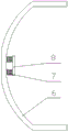
图5为图1中户型挡板部分的仰视图。FIG. 5 is a bottom view of the baffle part of the household type in FIG. 1 .
图6为图1中转动臂部分的结构示意图。FIG. 6 is a schematic structural diagram of the rotating arm part in FIG. 1 .
图7为图6中设备托架部分的结构示意图。FIG. 7 is a schematic structural diagram of the device bracket part in FIG. 6 .
图8为图1拆下转动臂后的右视图。Fig. 8 is a right side view of Fig. 1 with the pivot arm removed.
图9为本发明设备托架的正面视图。Figure 9 is a front view of the device tray of the present invention.
图10为图9的后视图。FIG. 10 is a rear view of FIG. 9 .
图中:1、座椅,2、顶部托架,3、后支腿,4、前支腿,5、底板,6、弧形挡板,7、归位减震弹簧,8、磁力板,9、铰接座,10、扭簧轴,11、转动臂,12、设备托架,13、方套,14、定位销,15、调节螺栓,16、拉手,17、吸附平面,18、台阶,19、折边,20、橡胶垫,21、出位减震弹簧,22、橡胶块。In the picture: 1. Seat, 2. Top bracket, 3. Rear outrigger, 4. Front outrigger, 5. Bottom plate, 6. Curved baffle, 7. Return shock spring, 8. Magnetic plate, 9. Hinged seat, 10, torsion spring shaft, 11, rotating arm, 12, equipment bracket, 13, square sleeve, 14, locating pin, 15, adjusting bolt, 16, handle, 17, adsorption plane, 18, step, 19, hemming, 20, rubber pad, 21, out of position shock-absorbing spring, 22, rubber block.
具体实施方式Detailed ways
下面将结合本发明实施例中的附图,对本发明实施例中的技术方案进行清楚、完整地描述,显然,所描述的实施例仅仅是本发明一部分实施例,而不是全部的实施例。基于本发明中的实施例,本领域普通技术人员在没有做出创造性劳动前提下所获得的所有其他实施例,都属于本发明保护的范围。The technical solutions in the embodiments of the present invention will be clearly and completely described below with reference to the accompanying drawings in the embodiments of the present invention. Obviously, the described embodiments are only a part of the embodiments of the present invention, but not all of the embodiments. Based on the embodiments of the present invention, all other embodiments obtained by those of ordinary skill in the art without creative efforts shall fall within the protection scope of the present invention.
请参阅图1-10,本发明提供一种技术方案:一种轨道交通车辆客厢用座椅,包括座椅1,所述座椅1下部与顶部托架2可拆卸连接,所述顶部托架2与后支腿3以及前支腿4焊接,所述后支腿3和所述前支腿4的底部均与底板5焊接,所述前支腿4之间可拆卸连接有弧形挡板6,所述弧形挡板6中部通过归位减震弹簧7与磁力板8连接,所述顶部托架2的前部下方具有铰接座9,所述铰接座9通过扭簧轴10与转动臂11铰接,所述转动臂11的端部与设备托架12一面的方套13插接配合并通过定位销14固定,所述设备托架12上螺接有调节螺栓15,所述转动臂11的中部一面具有拉手16,所述转动臂11的中部另一面加工有吸附平面17,所述吸附平面17与所述磁力板8适配,所述设备托架12上加工有台阶18,所述调节螺栓15与所述台阶18螺接并贯穿所述设备托架12,所述设备托架12的一边加工有回钩状的折边19,所述设备托架12上贴设有橡胶垫20,所述座椅1前端下方通过若干出位减震弹簧21与橡胶块22连接,所述橡胶块22与所述转动臂11适配。1-10, the present invention provides a technical solution: a seat for a passenger compartment of a rail transit vehicle, comprising a
工作原理:在使用该轨道交通车辆客厢用座椅时,转动臂11在不用的情况下是翻转到座椅1下方收纳起来的,不锈钢材质制作的转动臂11的吸附平面17会被磁力板8吸住,当乘客坐在座椅1上需要使用设备托架12来放置手机或平板电脑这类移动设备时,使用者可伸手拉住拉手16,克服磁力板8对转动臂11的吸附力将转动臂11与磁力板8分开,拉开后,则转动臂11会在扭簧轴10的回弹力作用下自动转动到座椅1上方位置,这个过程由于惯性原因,转动臂11转出速度越来越快,为了避免转动臂11与座椅1发生磕碰,座椅1前端下方的橡胶块22就起到减震作用,转动臂11转出后会与橡胶块22接触,而橡胶块22通过出位减震弹簧21与座椅1连接,在出位减震弹簧21和橡胶块22的双重减震作用下,转动臂11不会与座椅1发生硬性磕碰,避免了座椅1或转动臂11被磕伤磕坏的情况,转动臂11转出后,则乘客可将手机或平板电脑放在设备托架12上,设备托架12的折边19可防止手机或平板电脑滑落,设备托架12上的橡胶垫20起到防滑作用,调节螺栓15通过旋转可以改变伸出到设备托架12上方部分的长度,而手机和平板电脑就会在调节螺栓15的支撑作用下改变倾角,这样就实现了调节手机或平板电脑放置角度的目的,当乘客不需要使用设备托架12时,则克服扭簧轴10的弹力将转动臂11推回到座椅1下方,使得转动臂11的吸附平面17与磁力板8接触,则可完成转动臂11与磁力板8的配合,归位减震弹簧7起到减震作用,避免转动臂11推回时转动臂11与磁力板8发生硬性磕碰而损坏。Working principle: When using the passenger compartment seat of the rail transit vehicle, the rotating
尽管已经示出和描述了本发明的实施例,对于本领域的普通技术人员而言,可以理解在不脱离本发明的原理和精神的情况下可以对这些实施例进行多种变化、修改、替换和变型,本发明的范围由所附权利要求及其等同物限定。Although embodiments of the present invention have been shown and described, it will be understood by those skilled in the art that various changes, modifications, and substitutions can be made in these embodiments without departing from the principle and spirit of the invention and modifications, the scope of the present invention is defined by the appended claims and their equivalents.
Claims (5)
Priority Applications (1)
| Application Number | Priority Date | Filing Date | Title |
|---|---|---|---|
| CN201910877672.3A CN110509941B (en) | 2019-09-17 | 2019-09-17 | Seat for passenger compartment of rail transit vehicle |
Applications Claiming Priority (1)
| Application Number | Priority Date | Filing Date | Title |
|---|---|---|---|
| CN201910877672.3A CN110509941B (en) | 2019-09-17 | 2019-09-17 | Seat for passenger compartment of rail transit vehicle |
Publications (2)
| Publication Number | Publication Date |
|---|---|
| CN110509941A CN110509941A (en) | 2019-11-29 |
| CN110509941B true CN110509941B (en) | 2020-07-28 |
Family
ID=68632445
Family Applications (1)
| Application Number | Title | Priority Date | Filing Date |
|---|---|---|---|
| CN201910877672.3A Active CN110509941B (en) | 2019-09-17 | 2019-09-17 | Seat for passenger compartment of rail transit vehicle |
Country Status (1)
| Country | Link |
|---|---|
| CN (1) | CN110509941B (en) |
Citations (4)
| Publication number | Priority date | Publication date | Assignee | Title |
|---|---|---|---|---|
| CN101519051A (en) * | 2007-10-23 | 2009-09-02 | 格拉默股份有限公司 | Seat with extendable table |
| CN102846058A (en) * | 2011-06-29 | 2013-01-02 | 上海阿旺特家具有限公司 | Chair capable of facilitating use of tablet computer |
| CN203063949U (en) * | 2013-01-15 | 2013-07-17 | 陈勇 | Train seat with book support |
| CN204420511U (en) * | 2015-01-15 | 2015-06-24 | 浙江大学 | A kind of clipping flat bracket |
Family Cites Families (1)
| Publication number | Priority date | Publication date | Assignee | Title |
|---|---|---|---|---|
| US20160001786A1 (en) * | 2014-07-03 | 2016-01-07 | Foster-Miller, Inc. | User-centered locomotive crew console |
-
2019
- 2019-09-17 CN CN201910877672.3A patent/CN110509941B/en active Active
Patent Citations (4)
| Publication number | Priority date | Publication date | Assignee | Title |
|---|---|---|---|---|
| CN101519051A (en) * | 2007-10-23 | 2009-09-02 | 格拉默股份有限公司 | Seat with extendable table |
| CN102846058A (en) * | 2011-06-29 | 2013-01-02 | 上海阿旺特家具有限公司 | Chair capable of facilitating use of tablet computer |
| CN203063949U (en) * | 2013-01-15 | 2013-07-17 | 陈勇 | Train seat with book support |
| CN204420511U (en) * | 2015-01-15 | 2015-06-24 | 浙江大学 | A kind of clipping flat bracket |
Also Published As
| Publication number | Publication date |
|---|---|
| CN110509941A (en) | 2019-11-29 |
Similar Documents
| Publication | Publication Date | Title |
|---|---|---|
| CN106166975B (en) | A kind of automotive seat folding table | |
| CN206664394U (en) | The foot-rest device and automobile of automobile | |
| CN110509941B (en) | Seat for passenger compartment of rail transit vehicle | |
| CN201021161Y (en) | Seat headrest with cushioning device | |
| CN106427717A (en) | Vehicular folding tray table | |
| CN108407686A (en) | A kind of chair used for buses to take a break convenient for passenger | |
| CN204161383U (en) | A kind of intercity motor train unit and seat assembly thereof | |
| CN111605485A (en) | A buffer and shock absorption structure for a car navigator | |
| CN218085208U (en) | A rear seat armrest that reduces the impact of bumps | |
| CN218720376U (en) | Intelligent enterprise information matching system | |
| US2673592A (en) | Hinged plate movable seat construction | |
| CN113944832A (en) | Notebook computer support | |
| CN211869470U (en) | A mobile rack for electromechanical equipment | |
| CN205181644U (en) | Wheelchair with buffer structure | |
| CN104044666A (en) | Rollover prevention support of electric bicycle | |
| CN211166713U (en) | Positioning and cushioning support for vehicle-mounted computer | |
| CN210881772U (en) | Vehicle-mounted computer operating table | |
| CN211943315U (en) | Damping device for railway vehicle | |
| CN109050562A (en) | A kind of Novel fire garage Lee's placing device | |
| CN206345615U (en) | A kind of constructional engineering vehicle | |
| JP3105824U (en) | Step over wheels | |
| CN211844527U (en) | Copper roll carrying vehicle | |
| CN111483369A (en) | Compression spring type vehicle seat vibration damping structure | |
| CN219192419U (en) | An electric vehicle that is convenient for carrying children | |
| CN219941105U (en) | Medical trolley with buffer structure |
Legal Events
| Date | Code | Title | Description |
|---|---|---|---|
| PB01 | Publication | ||
| PB01 | Publication | ||
| SE01 | Entry into force of request for substantive examination | ||
| SE01 | Entry into force of request for substantive examination | ||
| TA01 | Transfer of patent application right |
Effective date of registration: 20200702 Address after: 317100 Haiyou Street Jinye village, Sanmen County, Taizhou City, Zhejiang Province Applicant after: Sanmen KEBA Trade Co.,Ltd. Address before: 241002 College of Automobile and Track, Anhui Mechatronics Vocational and Technical College, No. 16 Wenjin West Road, Yijiang District Higher Education Park, Wuhu City, Anhui Province Applicant before: Zhang Guofan |
|
| TA01 | Transfer of patent application right | ||
| GR01 | Patent grant | ||
| GR01 | Patent grant | ||
| TR01 | Transfer of patent right |
Effective date of registration: 20211201 Address after: 276000 Room 518, administrative service center, No. 1, Renmin Road, Pingshang Town, Lingang Economic Development Zone, Linyi City, Shandong Province Patentee after: Linyi xingchuangda Intellectual Property Operation Co.,Ltd. Address before: 317100 Hai You Jie Dao Jin Ye Cun, Sanmen County, Taizhou City, Zhejiang Province Patentee before: Sanmen KEBA Trade Co.,Ltd. |
|
| TR01 | Transfer of patent right | ||
| TR01 | Transfer of patent right |
Effective date of registration: 20240123 Address after: Room 1102, Rongchuang Building, Pingshang Town, Lingang Economic Development Zone, Linyi City, Shandong Province, 276624 Patentee after: Linyi Shenggang Investment Development and Construction Co.,Ltd. Country or region after: China Address before: 276000 Room 518, administrative service center, No. 1, Renmin Road, Pingshang Town, Lingang Economic Development Zone, Linyi City, Shandong Province Patentee before: Linyi xingchuangda Intellectual Property Operation Co.,Ltd. Country or region before: China |
|
| TR01 | Transfer of patent right | ||
| TR01 | Transfer of patent right |
Effective date of registration: 20251201 Address after: 523000 Guangdong Province Dongguan City Chang'an Town Lianxin West Road No. 1 Patentee after: Dongguan City Ekide Metal & Plastic Product Ltd. Country or region after: China Address before: Room 1102, Rongchuang Building, Pingshang Town, Lingang Economic Development Zone, Linyi City, Shandong Province, 276624 Patentee before: Linyi Shenggang Investment Development and Construction Co.,Ltd. Country or region before: China |
|
| TR01 | Transfer of patent right |