CN110500021B - External sunshade combined window - Google Patents
External sunshade combined window Download PDFInfo
- Publication number
- CN110500021B CN110500021B CN201910692416.7A CN201910692416A CN110500021B CN 110500021 B CN110500021 B CN 110500021B CN 201910692416 A CN201910692416 A CN 201910692416A CN 110500021 B CN110500021 B CN 110500021B
- Authority
- CN
- China
- Prior art keywords
- window
- louver
- frame
- shutter
- sling
- Prior art date
- Legal status (The legal status is an assumption and is not a legal conclusion. Google has not performed a legal analysis and makes no representation as to the accuracy of the status listed.)
- Active
Links
Images


Classifications
-
- E—FIXED CONSTRUCTIONS
- E06—DOORS, WINDOWS, SHUTTERS, OR ROLLER BLINDS IN GENERAL; LADDERS
- E06B—FIXED OR MOVABLE CLOSURES FOR OPENINGS IN BUILDINGS, VEHICLES, FENCES OR LIKE ENCLOSURES IN GENERAL, e.g. DOORS, WINDOWS, BLINDS, GATES
- E06B7/00—Special arrangements or measures in connection with doors or windows
- E06B7/02—Special arrangements or measures in connection with doors or windows for providing ventilation, e.g. through double windows; Arrangement of ventilation roses
- E06B7/08—Louvre doors, windows or grilles
- E06B7/084—Louvre doors, windows or grilles with rotatable lamellae
- E06B7/086—Louvre doors, windows or grilles with rotatable lamellae interconnected for concurrent movement
-
- E—FIXED CONSTRUCTIONS
- E06—DOORS, WINDOWS, SHUTTERS, OR ROLLER BLINDS IN GENERAL; LADDERS
- E06B—FIXED OR MOVABLE CLOSURES FOR OPENINGS IN BUILDINGS, VEHICLES, FENCES OR LIKE ENCLOSURES IN GENERAL, e.g. DOORS, WINDOWS, BLINDS, GATES
- E06B9/00—Screening or protective devices for wall or similar openings, with or without operating or securing mechanisms; Closures of similar construction
- E06B9/02—Shutters, movable grilles, or other safety closing devices, e.g. against burglary
- E06B9/04—Shutters, movable grilles, or other safety closing devices, e.g. against burglary of wing type, e.g. revolving or sliding
-
- E—FIXED CONSTRUCTIONS
- E06—DOORS, WINDOWS, SHUTTERS, OR ROLLER BLINDS IN GENERAL; LADDERS
- E06B—FIXED OR MOVABLE CLOSURES FOR OPENINGS IN BUILDINGS, VEHICLES, FENCES OR LIKE ENCLOSURES IN GENERAL, e.g. DOORS, WINDOWS, BLINDS, GATES
- E06B9/00—Screening or protective devices for wall or similar openings, with or without operating or securing mechanisms; Closures of similar construction
- E06B9/24—Screens or other constructions affording protection against light, especially against sunshine; Similar screens for privacy or appearance; Slat blinds
- E06B9/26—Lamellar or like blinds, e.g. venetian blinds
- E06B9/28—Lamellar or like blinds, e.g. venetian blinds with horizontal lamellae, e.g. non-liftable
- E06B9/30—Lamellar or like blinds, e.g. venetian blinds with horizontal lamellae, e.g. non-liftable liftable
- E06B9/32—Operating, guiding, or securing devices therefor
- E06B9/322—Details of operating devices, e.g. pulleys, brakes, spring drums, drives
-
- E—FIXED CONSTRUCTIONS
- E06—DOORS, WINDOWS, SHUTTERS, OR ROLLER BLINDS IN GENERAL; LADDERS
- E06B—FIXED OR MOVABLE CLOSURES FOR OPENINGS IN BUILDINGS, VEHICLES, FENCES OR LIKE ENCLOSURES IN GENERAL, e.g. DOORS, WINDOWS, BLINDS, GATES
- E06B9/00—Screening or protective devices for wall or similar openings, with or without operating or securing mechanisms; Closures of similar construction
- E06B9/24—Screens or other constructions affording protection against light, especially against sunshine; Similar screens for privacy or appearance; Slat blinds
- E06B9/26—Lamellar or like blinds, e.g. venetian blinds
- E06B9/28—Lamellar or like blinds, e.g. venetian blinds with horizontal lamellae, e.g. non-liftable
- E06B9/30—Lamellar or like blinds, e.g. venetian blinds with horizontal lamellae, e.g. non-liftable liftable
- E06B9/32—Operating, guiding, or securing devices therefor
- E06B9/326—Details of cords, e.g. buckles, drawing knobs
Abstract
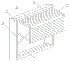
The invention provides an external sunshade combined window, which comprises a combined window frame, a built-in window sash arranged on the inner side of the combined window frame and a shutter arranged on the outer side of the combined window frame, wherein the shutter comprises a shutter transverse frame, a shutter vertical frame and a shutter enclosed in the shutter transverse frame and the shutter vertical frame, the shutter can be divided into an upper section and a lower section which are hinged, the upper section can extend outwards and extend upwards to form a certain angle, and the lower section can be bent downwards. The structure is firm and reliable, the safety is high, and the device can be particularly used in high-rise buildings; the sun-shading structure has the advantages of good sun-shading effect, capability of integrating the advantages of the louver and the overhung sun-shading structure, capability of easily realizing plane sun shading, capability of outwards overhanging and extending out a sun-shading form, convenience in adjusting the brightness and sight of the external sun-shading louver, and capability of realizing the advantages of good ventilation and sun shading when the built-in window is opened. When the shutter is closed, the shutter can prevent burglary, and when the shutter extends out, the shutter can be used as a fire escape passage.
Description
Technical Field
The invention belongs to the field of building doors and windows, and particularly relates to an external sunshade combined window.
Background
The existing sun-shading device for building doors and windows is divided into three types of inner sun-shading, middle sun-shading and outer sun-shading: the inner sunshade structure is characterized in that a curtain, a roller shutter and the like are arranged on the inner surface of a glass door and window, so that the inner sunshade structure is more in practical application; the middle sun-shading structure is that an inner louver is arranged in the middle of the interlayer of the hollow glass; the outer sunshade structure, namely a vertical blind window is arranged on the outer surface of a glass door or window or an outward extending upper-projecting sunshade device and the like is arranged, and is mainly applied to a bottom building. Compared with the three sun-shading devices, the external sun-shading product can directly block the solar radiation heat energy outside the glass window, so that the building energy saving of the external sun-shading product is 30 to 50 percent higher than that of the medium sun-shading product and the internal sun-shading product.
But the reason for limiting the further popularization of the external sunshade products is that: 1. most of the existing external sunshade products are special in structure, cannot be compatible with other window structures for buildings, need to take the external sunshade structure into consideration during initial design and construction of a window, and are not beneficial to external sunshade transformation and increase of the existing window; for example, the external sunshade of the vertical louver structure cannot be matched and adapted with an external-opening window such as a casement window. 2. The existing external sunshade product has the defects of single thin structure, unstable frame connection, poor load resistance and unreliable safety performance, so that the external sunshade product cannot be applied to high-rise buildings. 3. The sun-shading effect is not ideal, for example, when the upturning angle of the upturning type sun-shading structure is too large, the upturning type sun-shading structure can not shade the obliquely-projected sunlight to directly enter the room. 4. The vertical sun-shading shutter structure can block the exchange of indoor air and outside air to a certain extent while closing the blades to shade the sun, and influence indoor lighting.
Disclosure of Invention
The invention provides an external sunshade combined window, which is formed by combining an internal window sash (a window for the existing building) and an external sunshade shutter, has strong compatibility, and can be matched with structures such as a sliding window, a casement window or a multifunctional window in a matching way; the structure is firm and reliable, the safety is high, and the building is completely suitable for various buildings; the sun-shading structure has the advantages of good sun-shading effect, capability of integrating the advantages of the louver and the overhung sun-shading structure, capability of easily realizing plane sun shading, capability of outwards overhanging and extending out a sun-shading form, convenience in adjusting the brightness and sight of the external sun-shading louver, and capability of realizing the advantages of good ventilation and sun shading when the built-in window is opened.
The technical scheme adopted by the invention is as follows:
the combined window frame includes combined window horizontal frame and combined window vertical frame, its built-in window sash is mounted in the inner side of combined window frame, and the louver is mounted in the outer side of combined window frame, and the louver includes louver horizontal frame, louver vertical frame and louver enclosed in them, and the louver can be divided into upper and lower two sections which are hinged, and its upper section can be extended outwards and upwards extended to form a certain angle, and its lower section can be bent downwards. The built-in window sash can be a sliding window, a casement window or a multifunctional window and other various window types.
After the louver is stretched outwards and raised upwards, the louver is positioned through the inclined strut, and the inclined strut can be in various forms, such as a mechanical or pneumatic window strut and the like.
The connection part of the vertical frame of the louver between the upper section and the lower section of the louver is connected and plugged by a flexible plate, the flexible plate is fixedly anchored and connected with the upper section, and the flexible plate is freely connected with the lower section in a sliding manner. The flexible plate is used for plugging holes in the cross section of the vertical frame section of the louver, so that rainwater is prevented from entering the section, and the shape is attractive. The flexible plate can be made of materials such as a PVC plate or a strength plate. The endurance plate is also called PC plate, polycarbonate, solid plate, bulletproof glass, card bloom plate, plastic solid plate, polycarbonate plate and aviation perspective plate. The characteristics are as follows: the impact and breakage resistance strength of the composite material exceeds that of tempered glass and acrylic plates by hundreds of times, and the composite material is tough, safe, anti-theft and bulletproof. Can be arched and bent: good processability and strong plasticity, and can be bent into arch, semicircle and other patterns according to the actual needs of a construction site.
The middle of the louver is provided with a shaft hole, the louver shaft penetrates through the shaft hole, the cross section of the louver shaft is waist-shaped, and two ends of the louver shaft are positioned in sliding grooves on the sides of vertical frames of the louver. The shutter is a hard shutter made of aluminum alloy or other materials, the shutter can rotate around the shutter shaft to change the angle, but the shutter shaft cannot rotate and only can move up and down due to the waist shape of the shutter shaft and the limitation of the end part in the sliding groove on the side of the shutter frame.
The receipts of tripe are folded the mode and are had two kinds, and the realization of two kinds receipts are folded the mode, need change the structure of shutter inner part:
the first folding mode is that the shutter is folded from bottom to top, and the inner part structure of the shutter is arranged as follows: sling wire holes are formed in the two end portions of the louver shaft, sling wire holes are formed in the screwed-in bolts, a sling wire can penetrate into each sling wire hole, one end of the sling wire is fixedly connected to the lower end of the louver, the sling wire is turned through a lifting pulley fixed in the combined window frame to join the sling wires at the left end and the right end, the two sling wires are combined into a sling wire, and finally the other end of the sling wire is connected to a louver sling wire knob; the end part of the louver shaft is provided with a chain cable hole through which a chain cable penetrates, each louver shaft is uniformly distributed on the chain cable, and the chain cable is tightly pressed by a screwing-in bolt so that the louver shaft and the chain cable are fixed. The upper end of the chain cable is fixed in the upper transverse frame of the shutter, and the lower end of the chain cable is fixed at the end part of the sling; chain cable grooves are arranged beside the chain cables on the section of the vertical frame of the shutter. An operator rotates the shutter sling knob to wind the sling, the lowermost end of the shutter is gradually lifted, and the shutter is gradually folded from bottom to top.
Another kind of receipts is folded the mode and is, from last down folding of tripe, and the interior part structure of its shutter sets up to: one end of each sling is fixedly connected to the upper end of the louver, the slings are turned through a lifting pulley fixed in the combined window frame to join the left and right slings, the two slings are combined into one sling, and finally the other end of each sling is connected to a louver sling knob; the end part of the louver shaft is provided with a chain cable hole through which a chain cable penetrates, each louver shaft is uniformly distributed and fixed on the chain cable, the lower end of the chain cable is fixed in the lower transverse frame of the louver, and the upper end of the chain cable is fixed at the end part of the sling; chain cable grooves are arranged beside the chain cables on the section of the vertical frame of the shutter. An operator rotates a shutter sling knob to wind the sling, and the uppermost end of the shutter gradually descends under the action of gravity, so that the shutter is gradually folded from top to bottom.
The chain cable groove is arranged beside the chain cable, and when the louver rises and is folded, the chain lock groove is used for containing the folded chain cable.
The louver is provided with a rotating blade hole, a rotating blade cable penetrates through the rotating blade hole and is fixed with the rotating blade hole, the rotating blade cable is fixed with each louver through a cable knot, two ends of the rotating blade cable are fixedly connected to two sides of the louver at the uppermost end, the rotating blade cable is wound around a louver transverse frame below the rotating blade cable, and when a user pulls the rotating blade cable up and down, the angle deflection of the louver can be realized, and the light inlet quantity of the louver is adjusted.
The inner side of the lower frame of the transverse frame of the combined window is provided with a window lock, and window lock holes with the same shape as the window lock locking parts are correspondingly arranged on the louver frame. The section of the locking part of the window lock is specially-shaped, preferably waist-shaped, and after a window lock shaft penetrates into the combined window transverse frame and the shutter transverse frame respectively at a specific angle, the window lock can be rotated to connect and fix the two layers of window frames so as to achieve the locking and anti-theft functions.
Compared with the prior art, the invention has the advantages that:
1. the invention has higher structural stability and high safety, each part forms firm connection with the combined window frame, and the glass curtain wall can resist the interference of strong wind when being used in high-rise buildings, and the connection strength is the same as that of the existing glass curtain wall.
2. The invention has excellent sun-shading effect, integrates the advantages of the louver and the overhanging sun-shading structure, easily realizes plane sun-shading, can conveniently adjust the brightness and sight of the outer sun-shading louver in an overhanging and extending sun-shading mode, realizes the advantages of both ventilation and sun-shading when the built-in window is opened, and realizes the advantages of both ventilation and sun-shading when the built-in window is opened. When the shutter is closed, the shutter can prevent burglary, and when the shutter extends out, the shutter can be used as a fire escape passage.
Drawings
FIG. 1 is a schematic view of the external structure of the present invention in the open state;
FIG. 2 is a schematic side view of the present invention in an open state;
FIG. 3 is a schematic view of the cross-sectional structure A-A of FIG. 2;
FIG. 4 is an enlarged view at II of FIG. 2;
FIG. 5 is a schematic view of the cross-sectional structure of the cross-section D-D of FIG. 4
FIG. 6 is a schematic side view of the closed state of the present invention;
FIG. 7 is a schematic view of the cross-sectional structure of B-B of FIG. 6;
FIG. 8 is a schematic view of the cross-sectional structure of FIG. 6 at section C-C;
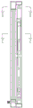
FIG. 9 is a schematic view of the blind of the present invention closed with the blind half pulled up and reflecting the blind, slings, pulleys and the blind sling knob;
FIG. 10 is an enlarged view of a portion of FIG. 9 at I;
FIG. 11 is a side view schematic view of the blind;
the reference numbers and names are as follows:
1. a window sash is arranged inside; 11. a combined window transverse frame; 12. a mullion of the combination window; 21. a horizontal frame of the shutter; 22. a louver mullion; 23. a blind window; 24. bracing; 25. a louver hinge; 26. a locking knob; 27. a window lock; 28. loose leaves; 29. a shutter sling knob; 30. a window lock hole; 31. a lifting pulley; 32. a louver shaft; 33, louver; 34. a chain cable hole; 35. a sling hole; 36. rotating the leaf hole; 37. a chain cable groove; 39. a flexible board; 40. a sling; 41. rotating a leaf cable; 42. and (4) a chain cable.
Detailed Description
Example 1
As shown in figures 1-10;
an external sun-shading combined window comprises a combined window frame, a combined window frame and a combined window, wherein the combined window frame comprises a combined window horizontal frame 11 and a combined window vertical frame 12, a built-in window sash 1 is arranged on the inner side of the combined window frame, a blind window 23 is arranged on the outer side of the combined window frame, the blind window 23 comprises a blind window horizontal frame 21, a blind window vertical frame 22 and a blind window 33 enclosed in the blind window horizontal frame and the blind window vertical frame, the blind window 23 can be divided into an upper section and a lower section which are hinged, the upper section can extend outwards and upwards extend to form a certain angle, and the lower section can be bent downwards;
the outward extending upper opening state of the louver 22 is positioned by a cross diagonal brace 24, one end of two support rods of the cross diagonal brace 24 is respectively fixed on an upper slide block and a lower slide block which are arranged in the combined window frame 21 through hinges, and the other end of the two support rods is respectively fixed on the upper end and the lower end of the outer side surface of the lower louver frame 23 through hinges; the upper sliding block can move up and down in an upper sliding groove in the combined window frame, and one end of the upper sliding block is hinged with the support rod A; the lower sliding block can move up and down in a lower sliding groove in the combined window frame, and one end of the lower sliding block is hinged with the supporting rod B; the other end of the support rod A and the other end of the support rod B are respectively hinged with the upper end and the lower end of the outer side surface of the lower section of the louver frame after the support rod A and the support rod B are crossed, and the crossed part of the two support rods is connected by a hinge; a section of through groove is respectively arranged at the middle motion interference section of each support rod, and a hinged sliding rivet is arranged for connection;
when the shutter is opened, the upper sliding block moves downwards, the lower sliding block moves upwards, the two supporting rods push out the lower section of the shutter like a scissors fork, then the locking knob is twisted into the positioning hole to be inserted and positioned, and the positioning holes are uniformly distributed on the combined window frame, so that different positioning holes can be selected for positioning according to the opening degree of the shutter. When the shutter is closed, the upper sliding block moves upwards, the lower sliding block moves downwards, the supporting rod is retracted, and finally the combined window frame is parallel to the combined window frame;
and a locking knob is connected to the lower sliding block in the combined window frame and is locked by being screwed into a locking hole formed in the combined window frame. The locking knob is fixed on the lower lengthened part of the lower sliding block;
the joint of the vertical frame 22 of the louver between the upper section and the lower section of the louver 23 is blocked by a groove-shaped endurance plate 39, the flexible plate 39 is fixedly connected with the upper section, and the flexible plate 39 is connected with the lower section in a sliding way;
a locking knob 26 is connected to the lower sliding block in the combined window frame 21, and the locking knob 26 is locked by being screwed into a locking hole formed in the combined window frame 21;
a shaft hole is formed in the middle of the louver 33, the louver shaft 32 penetrates through the shaft hole, the section of the louver shaft 32 is waist-shaped, and two ends of the louver shaft 32 are located in sliding grooves in the side edges of the louver frame 23;
one end of the sling 40 is fixedly connected with the upper end of the shutter 33, the sling 40 is turned by a lifting pulley 31 fixed in the combined window frame 11, the left end sling 40 and the right end sling 40 are combined, two slings 40 are combined into one sling, and the other end is connected to a shutter sling knob 29; the end part of each blind shaft 32 is provided with a chain cable hole 34 through which a chain cable 42 penetrates, each blind shaft 32 is uniformly fixed on the chain cable 42, the lower end of the chain cable 42 is fixed in the lower transverse frame 21 of the blind, and the upper end of the chain cable 42 is fixed at the end part of a suspension cable 40; chain cable grooves 37 are arranged beside the chain cables 42 on the cross section of the shutter mullion 22; the shutter can be folded from bottom to top;
the inner side of the lower frame of the combined window transverse frame 11 is provided with a window lock 27, and window lock holes 30 with the same shape of the locking parts of the window lock 27 are correspondingly arranged on the combined window transverse frame 11 and the shutter transverse frame 21.
Example 2
It differs from example 1 in that:
the louver 33 is provided with a rotating vane hole 36, a rotating vane cable 41 is inserted into the rotating vane hole 36 and fixed with the rotating vane hole 36, and the rotating vane cable 41 forms a closed loop cable through a rotating vane pulley 38 arranged in the upper transverse frame 21 of the louver. The louver 33 is provided with a rotating vane hole 36, a rotating vane cable 41 penetrates through the rotating vane hole 36 and is fixed with the rotating vane hole 36, the rotating vane cable 41 is fixed with each louver 33 through a cable knot, two ends of the rotating vane cable 41 are fixedly connected with two sides of the louver 33 at the uppermost end, and the rotating vane cable 41 winds through the louver transverse frame 21 below; the shutter can be folded from top to bottom.
Claims (7)
1. An external sunshade composite window, characterized in that: the combined window frame comprises a combined window transverse frame (11) and a combined window vertical frame (12), a built-in window sash (1) is installed on the inner side of the combined window frame, a blind window (23) is installed on the outer side of the combined window frame, the blind window (23) comprises a blind window transverse frame (21), a blind window vertical frame (22) and a plurality of blind windows (33) enclosed in the blind window transverse frame, the blind window (23) can be divided into an upper section and a lower section which are hinged, the upper section can extend outwards and upwards extend to form a certain angle, and the lower section can be bent downwards;
the outward extending upper-opening state of the louver (23) is positioned through a cross diagonal brace (24), one end of each of two support rods of the cross diagonal brace (24) is fixed on an upper sliding block and a lower sliding block which are arranged in the combined window frame (21) through hinges, and the other end of each of the two support rods is fixed on the upper end and the lower end of the outer side surface of the lower louver frame through hinges; the upper sliding block can move up and down in an upper sliding groove in the combined window frame, and one end of the upper sliding block is hinged with the support rod A; the lower sliding block can move up and down in a lower sliding groove in the combined window frame, and one end of the lower sliding block is hinged with the supporting rod B; the other end of the support rod A and the other end of the support rod B are respectively hinged with the upper end and the lower end of the outer side surface of the lower section of the louver frame after the support rod A and the support rod B are crossed, and the crossed part of the two support rods is connected by a hinge; the middle movement interference section of each support rod is provided with a section of through groove respectively and is connected with a hinged sliding rivet.
2. The external sunshade composite window of claim 1, wherein: the connection part of the vertical frame (22) of the louver between the upper section and the lower section of the louver (23) is connected and plugged by a flexible plate (39), the flexible plate (39) is fixedly connected with the upper section, and the flexible plate (39) is freely connected with the lower section in a sliding manner.
3. The external sunshade composite window of claim 1, wherein: the middle of the louver (33) is provided with a shaft hole, the louver shaft (32) penetrates through the shaft hole, the section of the louver shaft (32) is waist-shaped, and two ends of the louver shaft (32) are positioned in sliding grooves on the side edges of the louver vertical frames (22).
4. The external sunshade composite window of claim 3, wherein: sling holes (35) are formed in two end portions of the louver shaft (32), a sling (40) can penetrate through each sling hole (35), one end of the sling (40) is fixedly connected to the lower end of the louver (33), the sling (40) turns through a lifting pulley (31) fixed in the combined window frame (11), the slings (40) at the left end and the right end are converged, the two slings (40) are combined into a sling, and the other end of the sling is connected to a louver sling knob (29); the end part of the blind shaft (32) is provided with a chain cable hole (34) through which a chain cable (42) penetrates, each blind shaft (32) is uniformly fixed on the chain cable (42), the upper end of the chain cable (42) is fixed in the upper transverse frame (21) of the blind, and the lower end of the chain cable (42) is fixed at the end part of a suspension cable (40); chain cable grooves (37) are arranged beside the chain cables (42) on the cross section of the shutter mullion (22).
5. The external sunshade composite window of claim 1, wherein: the upper end of the louver (33) is fixedly connected with a sling (40), the sling (40) turns through a lifting pulley (31) fixed in the combined window frame (11), the slings (40) at the left end and the right end are converged, the two slings (40) are combined into one sling, and the other end of the sling is connected to a louver sling knob (29); the end part of the blind shaft (32) is provided with a chain cable hole (34) through which a chain cable (42) penetrates, each blind shaft (32) is uniformly fixed on the chain cable (42), the lower end of the chain cable (42) is fixed in the lower transverse frame (21) of the blind, and the upper end of the chain cable (42) is fixed at the end part of a suspension cable (40); chain cable grooves (37) are arranged beside the chain cables (42) on the cross section of the shutter mullion (22).
6. The external sunshade composite window of claim 1, wherein: the louver (33) is provided with a rotating blade hole (36), a rotating blade cable (41) penetrates through the rotating blade hole (36) and is fixed with the rotating blade hole, the rotating blade cable (41) is fixed with each louver (33) through a cable knot, two ends of the rotating blade cable (41) are fixedly connected with two sides of the louver (33) at the uppermost end, and the rotating blade cable (41) winds through the louver transverse frame (21) below.
7. The external sunshade composite window of claim 1, wherein: the inner side of the lower frame of the combined window transverse frame (11) is provided with a window lock (27), and the combined window transverse frame (11) and the shutter lower transverse frame (21) are correspondingly provided with window lock holes (30) with the same shapes as the locking parts of the window lock (27).
Priority Applications (1)
| Application Number | Priority Date | Filing Date | Title |
|---|---|---|---|
| CN201910692416.7A CN110500021B (en) | 2019-07-30 | 2019-07-30 | External sunshade combined window |
Applications Claiming Priority (1)
| Application Number | Priority Date | Filing Date | Title |
|---|---|---|---|
| CN201910692416.7A CN110500021B (en) | 2019-07-30 | 2019-07-30 | External sunshade combined window |
Publications (2)
| Publication Number | Publication Date |
|---|---|
| CN110500021A CN110500021A (en) | 2019-11-26 |
| CN110500021B true CN110500021B (en) | 2021-12-14 |
Family
ID=68587591
Family Applications (1)
| Application Number | Title | Priority Date | Filing Date |
|---|---|---|---|
| CN201910692416.7A Active CN110500021B (en) | 2019-07-30 | 2019-07-30 | External sunshade combined window |
Country Status (1)
| Country | Link |
|---|---|
| CN (1) | CN110500021B (en) |
Families Citing this family (4)
| Publication number | Priority date | Publication date | Assignee | Title |
|---|---|---|---|---|
| CN110965923A (en) * | 2020-01-22 | 2020-04-07 | 陆中选 | Plane external sunshade door and window |
| CN111576702B (en) * | 2020-05-30 | 2021-06-01 | 内蒙古科达铝业装饰工程有限公司 | Building curtain wall and mounting method thereof |
| CN112554764B (en) * | 2020-11-02 | 2023-01-17 | 陈艳 | Solar curtain |
| CN113445885A (en) * | 2021-07-31 | 2021-09-28 | 北京建磊国际装饰工程股份有限公司 | Double-layer linkage opening and closing glass curtain wall capable of adjusting indoor temperature difference |
Citations (2)
| Publication number | Priority date | Publication date | Assignee | Title |
|---|---|---|---|---|
| CN203531610U (en) * | 2013-08-08 | 2014-04-09 | 广东华昌铝厂有限公司 | Electric push-pull window |
| CN106948739A (en) * | 2016-01-06 | 2017-07-14 | 南宁市海汇新材料科技有限公司 | A kind of preparation method of brace type telescopic folding external sunshade shutter system |
Family Cites Families (7)
| Publication number | Priority date | Publication date | Assignee | Title |
|---|---|---|---|---|
| US4665964A (en) * | 1983-10-05 | 1987-05-19 | Zommers G Juris | Foldably extensible and collapsible track-mounted shade device for skylight-type window |
| CN2321854Y (en) * | 1997-07-18 | 1999-06-02 | 温永彪 | Multi-function window awning for sunshading and rain-proof |
| CN201705168U (en) * | 2010-06-22 | 2011-01-12 | 上海青鹰实业股份有限公司 | External sun shading double swing arm shutter |
| CN202047737U (en) * | 2011-04-07 | 2011-11-23 | 罗玉君 | Embedded type lily door window |
| CN103899239B (en) * | 2014-03-06 | 2015-06-17 | 哈尔滨工程大学 | Vertical retractable door with transmission function |
| CN107313677A (en) * | 2017-08-10 | 2017-11-03 | 谢安鹏 | One kind is exclusively used in planting greenhouse close window self-checking device |
| CN108571259A (en) * | 2018-05-17 | 2018-09-25 | 张伟 | A kind of drift guiding window |
-
2019
- 2019-07-30 CN CN201910692416.7A patent/CN110500021B/en active Active
Patent Citations (2)
| Publication number | Priority date | Publication date | Assignee | Title |
|---|---|---|---|---|
| CN203531610U (en) * | 2013-08-08 | 2014-04-09 | 广东华昌铝厂有限公司 | Electric push-pull window |
| CN106948739A (en) * | 2016-01-06 | 2017-07-14 | 南宁市海汇新材料科技有限公司 | A kind of preparation method of brace type telescopic folding external sunshade shutter system |
Also Published As
| Publication number | Publication date |
|---|---|
| CN110500021A (en) | 2019-11-26 |
Similar Documents
| Publication | Publication Date | Title |
|---|---|---|
| CN110500021B (en) | External sunshade combined window | |
| CN101550800B (en) | A multi-functional shutter | |
| CN201567909U (en) | Novel energy-saving roller window | |
| CN105484619A (en) | Inward tilt-turn window | |
| KR101930341B1 (en) | Blind APPARATUS FOR INSTALLED TO A CEILING, SLOPING SURFACE, CURVED SURFACE OF HOUSE AND SUNSHADE OUTSIDE OF HOUSE | |
| CN201367833Y (en) | Novel shutter | |
| CN110397395B (en) | Multipurpose blind curtain capable of changing shaft spacing | |
| CN212079150U (en) | Plane external sunshade door and window | |
| CN212001960U (en) | Overhauling skylight structure | |
| CN212359554U (en) | Double glazing curtain convenient to ventilate | |
| CN110965923A (en) | Plane external sunshade door and window | |
| CN210858526U (en) | Rolling gate | |
| CN209742738U (en) | Integrated external sunshade energy-saving window | |
| CN207863743U (en) | A kind of elevation of building bay window and air-conditioner outdoor unit bit combination structure | |
| CN201850967U (en) | Movable blind window | |
| KR101208010B1 (en) | blind | |
| DE10028433B4 (en) | Photovoltaic solar shutter with hexagonal solar cells | |
| CN110469256A (en) | A kind of triplex glass shutter | |
| CN107023250B (en) | A kind of rain-proof sunshade ventilation double-skin glass window | |
| CN214365809U (en) | Environment-friendly built-in louver glass window with ventilation and air purification functions | |
| CN220185021U (en) | Integrated inner sunshade multifunctional roller shutter window | |
| CN105781042B (en) | A kind of building external shading system of foldable unlatching | |
| CN215718200U (en) | Outward-opening top-hung sliding combined window | |
| CN220151232U (en) | Polyurethane window structure with ultralow energy consumption | |
| CN214303622U (en) | Double-layer energy-saving door and window capable of reasonably collecting light |
Legal Events
| Date | Code | Title | Description |
|---|---|---|---|
| PB01 | Publication | ||
| PB01 | Publication | ||
| SE01 | Entry into force of request for substantive examination | ||
| SE01 | Entry into force of request for substantive examination | ||
| TA01 | Transfer of patent application right |
Effective date of registration: 20211125 Address after: 530031 block a, 28 / F, international trade building, No.17 Jiangnan Road, Jiangnan District, Nanning City, Guangxi Zhuang Autonomous Region Applicant after: Guangxi Aoyuan Construction Technology Development Co.,Ltd. Address before: 530021 room 804, building B, No. 58 Jinhu Road, Qingxiu District, Nanning City, Guangxi Zhuang Autonomous Region Applicant before: Lu Zhongxuan |
|
| TA01 | Transfer of patent application right | ||
| GR01 | Patent grant | ||
| GR01 | Patent grant |