CN110495240B - Scheduling and transmission schemes for periodic and aperiodic control information - Google Patents
Scheduling and transmission schemes for periodic and aperiodic control information Download PDFInfo
- Publication number
- CN110495240B CN110495240B CN201880024387.0A CN201880024387A CN110495240B CN 110495240 B CN110495240 B CN 110495240B CN 201880024387 A CN201880024387 A CN 201880024387A CN 110495240 B CN110495240 B CN 110495240B
- Authority
- CN
- China
- Prior art keywords
- uci
- grant
- resource grant
- uci resource
- control information
- Prior art date
- Legal status (The legal status is an assumption and is not a legal conclusion. Google has not performed a legal analysis and makes no representation as to the accuracy of the status listed.)
- Active
Links
Images


Classifications
-
- H—ELECTRICITY
- H04—ELECTRIC COMMUNICATION TECHNIQUE
- H04J—MULTIPLEX COMMUNICATION
- H04J3/00—Time-division multiplex systems
- H04J3/16—Time-division multiplex systems in which the time allocation to individual channels within a transmission cycle is variable, e.g. to accommodate varying complexity of signals, to vary number of channels transmitted
- H04J3/1694—Allocation of channels in TDM/TDMA networks, e.g. distributed multiplexers
-
- H—ELECTRICITY
- H04—ELECTRIC COMMUNICATION TECHNIQUE
- H04L—TRANSMISSION OF DIGITAL INFORMATION, e.g. TELEGRAPHIC COMMUNICATION
- H04L5/00—Arrangements affording multiple use of the transmission path
- H04L5/003—Arrangements for allocating sub-channels of the transmission path
- H04L5/0053—Allocation of signaling, i.e. of overhead other than pilot signals
-
- H—ELECTRICITY
- H04—ELECTRIC COMMUNICATION TECHNIQUE
- H04L—TRANSMISSION OF DIGITAL INFORMATION, e.g. TELEGRAPHIC COMMUNICATION
- H04L5/00—Arrangements affording multiple use of the transmission path
- H04L5/003—Arrangements for allocating sub-channels of the transmission path
- H04L5/0078—Timing of allocation
- H04L5/0082—Timing of allocation at predetermined intervals
-
- H—ELECTRICITY
- H04—ELECTRIC COMMUNICATION TECHNIQUE
- H04L—TRANSMISSION OF DIGITAL INFORMATION, e.g. TELEGRAPHIC COMMUNICATION
- H04L5/00—Arrangements affording multiple use of the transmission path
- H04L5/0091—Signaling for the administration of the divided path
- H04L5/0094—Indication of how sub-channels of the path are allocated
-
- H—ELECTRICITY
- H04—ELECTRIC COMMUNICATION TECHNIQUE
- H04W—WIRELESS COMMUNICATION NETWORKS
- H04W72/00—Local resource management
- H04W72/12—Wireless traffic scheduling
- H04W72/1263—Mapping of traffic onto schedule, e.g. scheduled allocation or multiplexing of flows
- H04W72/1268—Mapping of traffic onto schedule, e.g. scheduled allocation or multiplexing of flows of uplink data flows
-
- H—ELECTRICITY
- H04—ELECTRIC COMMUNICATION TECHNIQUE
- H04W—WIRELESS COMMUNICATION NETWORKS
- H04W72/00—Local resource management
- H04W72/20—Control channels or signalling for resource management
- H04W72/23—Control channels or signalling for resource management in the downlink direction of a wireless link, i.e. towards a terminal
-
- H—ELECTRICITY
- H04—ELECTRIC COMMUNICATION TECHNIQUE
- H04W—WIRELESS COMMUNICATION NETWORKS
- H04W72/00—Local resource management
- H04W72/50—Allocation or scheduling criteria for wireless resources
- H04W72/535—Allocation or scheduling criteria for wireless resources based on resource usage policies
-
- H—ELECTRICITY
- H04—ELECTRIC COMMUNICATION TECHNIQUE
- H04L—TRANSMISSION OF DIGITAL INFORMATION, e.g. TELEGRAPHIC COMMUNICATION
- H04L5/00—Arrangements affording multiple use of the transmission path
- H04L5/0001—Arrangements for dividing the transmission path
- H04L5/0003—Two-dimensional division
- H04L5/0005—Time-frequency
- H04L5/0007—Time-frequency the frequencies being orthogonal, e.g. OFDM(A), DMT
- H04L5/001—Time-frequency the frequencies being orthogonal, e.g. OFDM(A), DMT the frequencies being arranged in component carriers
-
- H—ELECTRICITY
- H04—ELECTRIC COMMUNICATION TECHNIQUE
- H04L—TRANSMISSION OF DIGITAL INFORMATION, e.g. TELEGRAPHIC COMMUNICATION
- H04L5/00—Arrangements affording multiple use of the transmission path
- H04L5/0001—Arrangements for dividing the transmission path
- H04L5/0014—Three-dimensional division
- H04L5/0023—Time-frequency-space
-
- H—ELECTRICITY
- H04—ELECTRIC COMMUNICATION TECHNIQUE
- H04W—WIRELESS COMMUNICATION NETWORKS
- H04W72/00—Local resource management
- H04W72/20—Control channels or signalling for resource management
- H04W72/21—Control channels or signalling for resource management in the uplink direction of a wireless link, i.e. towards the network
Abstract
Aspects of the present disclosure provide scheduling and transmission schemes for managing multiple Uplink Control Information (UCI) resource grants for periodic UCI and aperiodic UCI for a particular User Equipment (UE). A grant selection rule may be defined to enable the UE to select one or more of the UCI resource grants allocated within a particular time period. Moreover, the grant selection rule may further enable the UE to combine both periodic and aperiodic UCI within a particular UCI resource grant. The grant selection rule may further enable the UE to multiplex UCI on multiple UCI resource grants. Other aspects, embodiments, and features are also claimed and described.
Description
Cross Reference to Related Applications
This application claims priority and benefit from provisional application No. 62/485,862, filed at U.S. patent and trademark office at 14.4.2017 and non-provisional application No. 15/951,691, filed at 12.4.2018, which are hereby incorporated by reference in their entirety as if fully set forth below and for all applicable purposes.
Technical Field
The techniques discussed below relate generally to wireless communication systems and, more particularly, to scheduling and transmission of Uplink Control Information (UCI).
Introduction to
Wireless transmissions between a base station and one or more User Equipments (UEs) within a cell are typically scheduled in each subframe or time slot. For example, a base station may assign resources (e.g., time-frequency resources) to downlink transmissions to one or more UEs and grant resources for uplink transmissions from one or more UEs. These downlink assignments and uplink grants may be provided to the UE via a Physical Downlink Control Channel (PDCCH) or via higher layer signaling, such as Radio Resource Control (RRC) signaling.
Uplink grants may be designated for uplink user data traffic. Further, an Uplink Control Information (UCI) resource grant may be designated for a particular UCI. Examples of UCI include scheduling requests for uplink user data traffic, channel Quality Information (CQI), multiple-input multiple-output (MIMO) parameters such as rank and precoder index, and hybrid automatic repeat request (HARQ) feedback transmissions such as an Acknowledgement (ACK) or Negative Acknowledgement (NACK) of downlink transmissions. UCI may be transmitted via a Physical Uplink Control Channel (PUCCH) or via a Physical Uplink Shared Channel (PUSCH). Further, the base station may allocate UCI resources to the UE dynamically using dynamic signaling (e.g., as Downlink Control Information (DCI) within the PDCCH) or semi-statically using higher layer signaling (e.g., RRC signaling). In legacy (e.g., 4G) wireless communication networks, such as Long Term Evolution (LTE) wireless networks, PUCCH resources are typically allocated semi-statically, while PUSCH resources are typically allocated dynamically.
However, in next generation (e.g., 5G) wireless networks, such as New Radio (NR) wireless networks, PUCCH resources may be semi-statically and dynamically allocated. The semi-static PUCCH resource grant may carry, for example, a periodic UCI, such as a periodic scheduling request, CQI, and HARQ feedback transmission for periodic or semi-persistent downlink transmissions. The dynamic PUCCH or PUSCH grant may carry, for example, aperiodic UCI, such as HARQ feedback transmission for regular downlink transmission (e.g., aperiodic or semi-persistent downlink transmission), HARQ feedback transmission for certain PDCCH information, and aperiodic CQI reports. Research and development continues into various mechanisms for managing both dynamic (aperiodic) and semi-static (periodic) UCI grants.
Brief summary of some examples
The following presents a simplified summary of one or more aspects of the disclosure in order to provide a basic understanding of such aspects. This summary is not an extensive overview of all contemplated features of the disclosure, and is intended to neither identify key or critical elements of all aspects of the disclosure, nor delineate the scope of any or all aspects of the disclosure. Its sole purpose is to present some concepts of one or more aspects of the disclosure in a simplified form as a prelude to the more detailed description that is presented later.
Various aspects of the present disclosure relate to scheduling and transmission schemes for managing multiple Uplink Control Information (UCI) resource grants for periodic UCI and aperiodic UCI for a particular UE. A grant selection rule may be defined to enable the UE to select one or more of the UCI resource grants allocated within a particular time period. Moreover, the grant selection rule may further enable the UE to combine both periodic and aperiodic UCI for transmission on the selected uplink resources. This may enable some of the granted uplink resources to be released for other uplink transmissions. The grant selection rules may further enable the UE to multiplex UCI on multiple UCI resource grants to provide greater coding gain as a result of a larger block size.
In one aspect of the disclosure, a method of wireless communication in a wireless communication network is provided. The method comprises the following steps: the method may include receiving, at a scheduled entity, a first Uplink Control Information (UCI) resource grant that allocates a first set of resource elements used by the scheduled entity to transmit first uplink control information to a scheduling entity, receiving, at the scheduled entity, a second UCI resource grant that allocates a second set of resource elements used by the scheduled entity to transmit second uplink control information to the scheduling entity, and selecting at least one of the first UCI resource grant or the second UCI resource grant based on one or more grant selection rules when a time difference between the first set of resource elements and the second set of resource elements is less than a threshold indicating that the first UCI resource grant and the second UCI resource grant occur within a same time period, wherein the threshold corresponds to the time period.
Another aspect of the present disclosure provides a scheduled entity in wireless communication with a scheduling entity in a wireless communication network. The scheduled entity includes a processor, a transceiver communicatively coupled to the processor, and a memory communicatively coupled to the processor. The processor is configured to: the method may include receiving, via a transceiver, a first Uplink Control Information (UCI) resource grant that allocates a first set of resource elements used by a scheduled entity to transmit first uplink control information to a scheduling entity, receiving, via the transceiver, a second UCI resource grant that allocates a second set of resource elements used by the scheduled entity to transmit second uplink control information to the scheduling entity, and selecting at least one of the first UCI resource grant or the second UCI resource grant based on one or more grant selection rules when a time difference between the first set of resource elements and the second set of resource elements is less than a threshold indicating that the first UCI resource grant and the second UCI resource grant occur within a same time period, wherein the threshold corresponds to the time period.
Another aspect of the present disclosure provides a scheduled entity in wireless communication with a scheduling entity in a wireless communication network. The scheduled entity includes: the apparatus generally includes means for receiving a first Uplink Control Information (UCI) resource grant allocating a first set of resource elements used by a scheduled entity to transmit first uplink control information to a scheduling entity, means for receiving a second UCI resource grant allocating a second set of resource elements used by the scheduled entity to transmit second uplink control information to the scheduling entity, and means for selecting at least one of the first UCI resource grant or the second UCI resource grant based on one or more grant selection rules when a time difference between the first set of resource elements and the second set of resource elements is less than a threshold indicating that the first UCI resource grant and the second UCI resource grant occurred within a same time period, wherein the threshold corresponds to the time period.
Another aspect of the disclosure provides a non-transitory computer-readable medium storing computer-executable code. The non-transitory computer-readable medium includes code for causing a computer to: the method may include receiving, at a scheduled entity, a first Uplink Control Information (UCI) resource grant that allocates a first set of resource elements used by the scheduled entity to transmit first uplink control information to a scheduling entity, receiving, at the scheduled entity, a second UCI resource grant that allocates a second set of resource elements used by the scheduled entity to transmit second uplink control information to the scheduling entity, and selecting at least one of the first UCI resource grant or the second UCI resource grant based on one or more grant selection rules when a time difference between the first set of resource elements and the second set of resource elements is less than a threshold indicating that the first UCI resource grant and the second UCI resource grant occur within a same time period, wherein the threshold corresponds to the time period.
These and other aspects of the present invention will be more fully understood after a review of the following detailed description. Other aspects, features and embodiments of the present invention will become apparent to those ordinarily skilled in the art upon review of the following description of specific exemplary embodiments of the invention in conjunction with the accompanying figures. While features of the invention may be discussed below with respect to certain embodiments and figures, all embodiments of the invention can include one or more of the advantageous features discussed herein. In other words, while one or more embodiments may have been discussed as having certain advantageous features, one or more of such features may also be used in accordance with the various embodiments of the invention discussed herein. In a similar manner, although example embodiments may be discussed below as device, system, or method embodiments, it should be appreciated that such example embodiments may be implemented in a variety of devices, systems, and methods.
Brief Description of Drawings
Fig. 1 is a schematic illustration of a wireless communication system.
Fig. 2 is a conceptual illustration of an example of a radio access network.
Fig. 3 is a diagram illustrating an example of a frame structure used in a radio access network.
Fig. 4 is a diagram illustrating an example of a Downlink (DL) centric time slot.
Fig. 5 is a diagram illustrating an example of an Uplink (UL) centric time slot.
Fig. 6 is a signaling diagram illustrating exemplary signaling for dynamic scheduling.
Fig. 7 is a signaling diagram illustrating exemplary signaling for semi-persistent scheduling.
Fig. 8 is a diagram illustrating an example of multiple Uplink Control Information (UCI) resource grants occurring within a given time period, in accordance with some aspects of the present disclosure.
Fig. 9 is a diagram illustrating time periods including one or more Transmission Time Intervals (TTIs) according to some aspects of the present disclosure.
Fig. 10 is a diagram illustrating an example of selecting one or more UCI resource grants to transmit UCI within a given time period, in accordance with some aspects of the present disclosure.
Fig. 11 is a diagram illustrating another example of selecting one or more UCI resources to transmit UCI within a given time period, in accordance with some aspects of the present disclosure.
Fig. 12 is a diagram illustrating another example of selecting one or more UCI resource grants to transmit UCI within a given time period, in accordance with some aspects of the present disclosure.
Fig. 13 is a diagram illustrating another example of selecting one or more UCI resource grants to transmit UCI within a given time period, in accordance with some aspects of the present disclosure.
Fig. 14 is a diagram illustrating an example of a threshold value set equal to a time period of one OFDM symbol to determine alignment of the start and/or end of UCI resource grants, according to some aspects of the present disclosure.
Fig. 15 is a block diagram illustrating an example of a hardware implementation of a scheduling entity employing a processing system in accordance with some aspects of the present disclosure.
Fig. 16 is a block diagram illustrating an example of a hardware implementation of a scheduled entity employing a processing system in accordance with some aspects of the present disclosure.
Fig. 17 is a diagram illustrating an example of a Physical Downlink Control Channel (PDCCH) carrying downlink control information, according to some aspects of the disclosure.
Fig. 18 is a flow diagram illustrating an example process for managing multiple Uplink Control Information (UCI) resource grants to transmit UCI in a wireless communication network, in accordance with some aspects of the present disclosure.
Fig. 19 is a flow diagram illustrating another example process for managing multiple Uplink Control Information (UCI) resource grants to transmit UCI in a wireless communication network, in accordance with some aspects of the present disclosure.
Fig. 20 is a flow diagram illustrating another example process of an example process for managing multiple Uplink Control Information (UCI) resource grants to transmit UCI in a wireless communication network in accordance with some aspects of the present disclosure.
Fig. 21 is a flow diagram illustrating another example process for managing multiple Uplink Control Information (UCI) resource grants to transmit UCI in a wireless communication network in accordance with some aspects of the present disclosure.
Fig. 22 is a flow diagram illustrating an example process for managing multiple Uplink Control Information (UCI) resource grants to a scheduled entity to receive UCI in a wireless communication network, in accordance with some aspects of the present disclosure.
Detailed Description
The detailed description set forth below in connection with the appended drawings is intended as a description of various configurations and is not intended to represent the only configurations in which the concepts described herein may be practiced. The detailed description includes specific details to provide a thorough understanding of the various concepts. It will be apparent, however, to one skilled in the art that these concepts may be practiced without these specific details. In some instances, well-known structures and components are shown in block diagram form in order to avoid obscuring such concepts.
While aspects and embodiments in this application are described by way of illustration of some examples, those skilled in the art will appreciate that additional implementations and use cases may be generated in many different arrangements and scenarios. The innovations described herein may be implemented across many different platform types, devices, systems, shapes, sizes, packaging arrangements. For example, embodiments and/or uses can be produced via integrated chip embodiments and other non-module component-based devices (e.g., end-user devices, vehicles, communication devices, computing devices, industrial equipment, retail/purchase devices, medical devices, AI-enabled devices, etc.). While some examples may or may not be specific to each use case or application, broad applicability of the described innovations may occur. Implementations may range from chip-level or modular components to non-module, non-chip-level implementations, and further to aggregated, distributed, or OEM devices or systems incorporating one or more aspects of the described innovations. In some practical settings, a device incorporating the described aspects and features may also include additional components and features as necessary to implement and practice the various embodiments as claimed and described. For example, the transmission and reception of wireless signals must include several components for analog and digital purposes (e.g., hardware components including antennas, RF chains, power amplifiers, modulators, buffers, processor(s), interleavers, adders/summers, etc.). The innovations described herein are intended to be practiced in a wide variety of devices, chip-level components, systems, distributed arrangements, end-user devices, and the like, of various sizes, shapes, and configurations.
The various concepts presented throughout this disclosure may be implemented across a wide variety of telecommunications systems, network architectures, and communication standards. Referring now to fig. 1, as an illustrative example and not limitation, aspects of the present disclosure are illustrated with reference to a wireless communication system 100. The wireless communication system 100 includes three interaction domains: a core network 102, a Radio Access Network (RAN) 104, and a User Equipment (UE) 106. By way of the wireless communication system 100, the UE 106 may be enabled to perform data communications with an external data network 110, such as, but not limited to, the internet.
The RAN 104 may implement any suitable wireless communication technology or technologies to provide radio access to the UEs 106. As one example, RAN 104 may operate in accordance with the third generation partnership project (3 GPP) New Radio (NR) specification, commonly referred to as 5G. As another example, the RAN 104 may operate under a mix of 5G NR and evolved universal terrestrial radio access network (eUTRAN) standards, commonly referred to as LTE. The 3GPP refers to this hybrid RAN as the next generation RAN, or NG-RAN. Of course, many other examples may be utilized within the scope of the present disclosure.
As illustrated, RAN 104 includes multiple base stations 108. Broadly, a base station is a network element in a radio access network responsible for radio transmission and reception in one or more cells to or from a UE. A base station may also be referred to variously by those skilled in the art as a Base Transceiver Station (BTS), a radio base station, a radio transceiver, a transceiver function, a Basic Service Set (BSS), an Extended Service Set (ESS), an Access Point (AP), a Node B (NB), an evolved node B (eNB), a g B node (gNB), or some other suitable terminology, in different technologies, standards, or contexts.
The radio access network 104 is further illustrated as supporting wireless communication for a plurality of mobile devices. A mobile device may be referred to as a User Equipment (UE) in the 3GPP standards, but may also be referred to by those skilled in the art as a Mobile Station (MS), a subscriber station, a mobile unit, a subscriber unit, a wireless unit, a remote unit, a mobile device, a wireless communications device, a remote device, a mobile subscriber station, an Access Terminal (AT), a mobile terminal, a wireless terminal, a remote terminal, a handset, a terminal, a user agent, a mobile client, a client, or some other suitable terminology. A UE may be a device that provides a user with access to network services.
Within this document, a "mobile" device does not necessarily need to have mobility capabilities, and may be stationary. The term mobile device or mobile equipment generally refers to a wide variety of equipment and technologies. A UE may include several hardware structural components sized, shaped, and arranged to facilitate communication; such components may include antennas, antenna arrays, RF chains, amplifiers, one or more processors, and so forth, electrically coupled to each other. For example, some non-limiting examples of mobile devices include mobile devices, cellular (cell) phones, smart phones, session Initiation Protocol (SIP) phones, laptops, personal Computers (PCs), notebooks, netbooks, smartbooks, tablets, personal Digital Assistants (PDAs), and a wide variety of embedded systems, e.g., corresponding to the "internet of things" (IoT). The mobile apparatus may additionally be a self-propelled or other transport vehicle, a remote sensor or actuator, a robot or robotic device, a satellite radio, a Global Positioning System (GPS) device, an object tracking device, a drone, a multi-axis vehicle, a quadcopter, a remote control device, a consumer, and/or a wearable device, such as glasses, wearable cameras, virtual reality devices, smart watches, health or fitness trackers, digital audio players (e.g., MP3 players), cameras, game consoles, and so forth. The mobile device may additionally be a digital home or smart home device, such as a home audio, video, and/or multimedia device, appliance, vending machine, smart lighting, home security system, smart meter, and so forth. The mobile device may additionally be a smart energy device, a security device, a solar panel or solar array, a city infrastructure device that controls electrical power (e.g., a smart grid), lighting, water, etc.; industrial automation and enterprise equipment; a logistics controller; agricultural equipment; military defense equipment, vehicles, aircraft, boats, and weaponry, among others. Still further, the mobile device may provide networked medical or telemedicine support, i.e., remote health care. The remote healthcare devices may include remote healthcare monitoring devices and remote healthcare supervisory devices whose communications may be given priority or preferential access over other types of information, for example in the form of prioritized access to critical service data transmissions and/or associated QoS for critical service data transmissions.
Wireless communication between RAN 104 and UE 106 may be described as utilizing an air interface. Transmissions from a base station (e.g., base station 108) to one or more UEs (e.g., UE 106) over the air interface may be referred to as Downlink (DL) transmissions. In accordance with certain aspects of the present disclosure, the term downlink may refer to a point-to-multipoint transmission originating at a scheduling entity (described further below; e.g., base station 108). Another way of describing this scheme may be to use the term broadcast channel multiplexing. Transmissions from a UE (e.g., UE 106) to a base station (e.g., base station 108) may be referred to as Uplink (UL) transmissions. According to further aspects of the disclosure, the term uplink may refer to a point-to-point transmission originating at a scheduled entity (described further below; e.g., the UE 106).
In some examples, access to the air interface may be scheduled, where a scheduling entity (e.g., base station 108) allocates resources for communication between some or all of the devices and equipment within its service area or cell. Within this disclosure, the scheduling entity may be responsible for scheduling, assigning, reconfiguring, and releasing resources for one or more scheduled entities, as discussed further below. That is, for scheduled communications, the UE 106 (which may be a scheduled entity) may utilize resources allocated by the scheduling entity 108.
As illustrated in fig. 1, the scheduling entity 108 may broadcast downlink traffic 112 to one or more scheduled entities 106. Broadly, the scheduling entity 108 is a node or device responsible for scheduling traffic (including downlink traffic 112 and, in some examples, also uplink traffic 116 from one or more scheduled entities 106 to the scheduling entity 108) in a wireless communication network. On the other hand, the scheduled entity 106 is a node or device that receives downlink control information 114 (including but not limited to scheduling information (e.g., grants), synchronization or timing information), or other control information from another entity in the wireless communication network, such as the scheduling entity 108.
In addition, uplink and/or downlink control information and/or traffic information may be divided in time into frames, subframes, slots, and/or symbols. As used herein, a symbol may refer to a unit of time that carries one Resource Element (RE) per subcarrier in an Orthogonal Frequency Division Multiplexing (OFDM) waveform. A slot may carry 7 or 14 OFDM symbols. A subframe may refer to a duration of 1 ms. Multiple subframes or slots may be grouped together to form a single frame or radio frame. Of course, these definitions are not required, and the waveforms may be organized using any suitable scheme, and the various time divisions of the waveforms may have any suitable duration.
In general, the base station 108 may include a backhaul interface for communicating with a backhaul portion 120 of a wireless communication system. The backhaul 120 may provide a link between the base station 108 and the core network 102. Further, in some examples, a backhaul network may provide interconnection between respective base stations 108. Various types of backhaul interfaces may be employed, such as direct physical connections using any suitable transport network, virtual networks, and so forth.
The core network 102 may be part of the wireless communication system 100 and may be independent of the radio access technology used in the RAN 104. In some examples, the core network 102 may be configured according to the 5G standard (e.g., 5 GC). In other examples, the core network 102 may be configured according to a 4G Evolved Packet Core (EPC), or any other suitable standard or configuration.
Referring now to fig. 2, a schematic illustration of a RAN 200 is provided by way of example and not limitation. In some examples, RAN 200 may be the same as RAN 104 described above and illustrated in fig. 1. The geographic area covered by the RAN 200 may be divided into cellular regions (cells) that may be uniquely identified by a User Equipment (UE) based on an identification broadcast from one access point or base station. Fig. 2 illustrates macro cells 202, 204, and 206, and small cell 208, each of which may include one or more sectors (not shown). A sector is a sub-area of a cell. All sectors within a cell are served by the same base station. A radio link within a sector may be identified by a single logical identification belonging to the sector. In a cell divided into sectors, the multiple sectors within the cell may be formed by groups of antennas, with each antenna responsible for communication with UEs in a portion of the cell.
In fig. 2, two base stations 210 and 212 are shown in cells 202 and 204; and a third base station 214 is shown controlling a Remote Radio Head (RRH) 216 in the cell 206. That is, the base station may have an integrated antenna, or may be connected to an antenna or RRH by a feeder cable. In the illustrated example, cells 202, 204, and 126 may be referred to as macro cells because base stations 210, 212, and 214 support cells having large sizes. Further, a base station 218 is shown in a small cell 208 (e.g., a microcell, picocell, femtocell, home base station, home node B, home enodeb, etc.), which small cell 208 may overlap with one or more macro cells. In this example, cell 208 may be referred to as a small cell because base station 218 supports cells having a relatively small size. Cell sizing may be done according to system design and component constraints.
It is to be understood that the radio access network 200 may include any number of wireless base stations and cells. Further, relay nodes may be deployed to extend the size or coverage area of a given cell. The base stations 210, 212, 214, 218 provide wireless access points to the core network for any number of mobile devices. In some examples, the base stations 210, 212, 214, and/or 218 may be the same as the base station/scheduling entity 108 described above and illustrated in fig. 1.
Within the RAN 200, cells may include UEs that may be in communication with one or more sectors of each cell. Further, each base station 210, 212, 214, and 218 may be configured to provide an access point to the core network 102 for all UEs in the respective cell (see fig. 1). For example, UEs 222 and 224 may be in communication with base station 210; UEs 226 and 228 may be in communication with base station 212; UEs 230 and 232 may be in communication with base station 214 via RRH 216; and the UE 234 may be in communication with the base station 218. In some examples, the UEs 222, 224, 226, 228, 230, 232, 234, 238, 240, and/or 242 may be the same as the UEs/scheduled entities 106 described above and illustrated in fig. 1.
In some examples, an Unmanned Aerial Vehicle (UAV) 220 (which may be a drone or a quadcopter) may be a mobile network node and may be configured to function as a UE. For example, the UAV 220 may operate within the cell 202 by communicating with the base station 210.
In a further aspect of RAN 200, side-link signals may be used between UEs without having to rely on scheduling or control information from the base station. For example, two or more UEs (e.g., UEs 226 and 228) may communicate with each other using peer-to-peer (P2P) or sidelink signals 227 without relaying the communication through a base station (e.g., base station 212). In a further example, UE 238 is illustrated as communicating with UEs 240 and 242. Here, UE 238 may serve as a scheduling entity or a primary side link device, and UEs 240 and 242 may serve as scheduled entities or non-primary (e.g., secondary) side link devices. In yet another example, the UE may function as a scheduling entity in a device-to-device (D2D), peer-to-peer (P2P), or vehicle-to-vehicle (V2V) network, and/or in a mesh network. In the mesh network example, UEs 240 and 242 may optionally communicate directly with each other in addition to communicating with scheduling entity 238. Thus, in a wireless communication system having scheduled access to time-frequency resources and having a cellular configuration, a P2P configuration, or a mesh configuration, a scheduling entity and one or more scheduled entities may communicate utilizing the scheduled resources. In some examples, the sidelink signal 227 includes sidelink traffic and sidelink control. The side link control information may include a request signal in some examples, such as a Request To Send (RTS), a Source Transport Signal (STS), and/or a Direction Selection Signal (DSS). The request signal is available for the scheduled entity to request a time duration to maintain a sidelink channel available for sidelink signals. The sidelink control information may further include a response signal such as a Clear To Send (CTS) and/or a Destination Received Signal (DRS). The response signal is available for the scheduled entity to indicate the availability of the sidelink channel, e.g., within the requested time duration. The exchange of request and response signals (e.g., handshaking) may enable different scheduled entities performing sidelink communications to negotiate the availability of sidelink channels prior to the communication of sidelink traffic information.
In the radio access network 200, the ability of a UE to communicate when moving independent of its location is referred to as mobility. The various physical channels between the UE and the radio access network are typically set up, maintained and released under the control of access and mobility management functions (AMF, not illustrated, part of the core network 102 in fig. 1), which may include a Security Context Management Function (SCMF) that manages the security context for both control plane and user plane functionality, and a security anchor point function (SEAF) that performs authentication.
The radio access network 200 may utilize DL-based mobility or UL-based mobility to enable mobility and handover (i.e., transfer of a UE's connection from one radio channel to another). In a network configured for DL-based mobility, during a call with a scheduling entity, or at any other time, a UE may monitor various parameters of signals from its serving cell as well as various parameters of neighboring cells. Depending on the quality of these parameters, the UE may maintain communication with one or more neighboring cells. During this time, if the UE moves from one cell to another cell, or if the signal quality from the neighboring cell exceeds the signal quality from the serving cell for a given amount of time, the UE may perform a handover or handoff from the serving cell to the neighboring (target) cell. For example, UE 224 (illustrated as a vehicle, but any suitable form of UE may be used) may move from a geographic area corresponding to its serving cell 202 to a geographic area corresponding to a neighbor cell 206. When the signal strength or quality from the neighbor cell 206 exceeds the signal strength or quality of its serving cell 202 for a given amount of time, the UE 224 may transmit a report message to its serving base station 210 indicating the condition. In response, UE 224 may receive a handover command and the UE may experience a handover to cell 206.
In a network configured for UL-based mobility, UL reference signals from each UE may be used by the network to select a serving cell for each UE. In some examples, the base stations 210, 212, and 214/216 may broadcast a unified synchronization signal (e.g., a unified Primary Synchronization Signal (PSS), a unified Secondary Synchronization Signal (SSS), and a unified Physical Broadcast Channel (PBCH)). UEs 222, 224, 226, 228, 230, and 232 may receive the unified synchronization signals, derive carrier frequencies and slot timings from the synchronization signals, and transmit uplink pilot or reference signals in response to the derived timings. The uplink pilot signals transmitted by the UE (e.g., UE 224) may be received concurrently by two or more cells (e.g., base stations 210 and 214/216) within the radio access network 200. Each of these cells may measure the strength of the pilot signal, and the radio access network (e.g., one or more of base stations 210 and 214/216 and/or a central node within the core network) may determine the serving cell for UE 224. As the UE 224 moves through the radio access network 200, the network may continue to monitor the uplink pilot signals transmitted by the UE 224. When the signal strength or quality of the pilot signal measured by the neighboring cell exceeds the signal strength or quality measured by the serving cell, the network 200 may handover the UE 224 from the serving cell to the neighboring cell with or without notification of the UE 224.
Although the synchronization signal transmitted by the base stations 210, 212, and 214/216 may be uniform, the synchronization signal may not identify a particular cell, but may identify a region that includes multiple cells operating on the same frequency and/or having the same timing. The use of zones in a 5G network or other next generation communication network enables an uplink-based mobility framework and improves the efficiency of both the UE and the network, as the number of mobility messages that need to be exchanged between the UE and the network can be reduced.
In various implementations, the air interface in the radio access network 200 may utilize a licensed spectrum, an unlicensed spectrum, or a shared spectrum. Licensed spectrum typically provides exclusive use of a portion of the spectrum by means of mobile network operators who purchase licenses from government regulatory agencies. Unlicensed spectrum provides shared use of a portion of spectrum without government-granted licenses. Any operator or device may gain access, although some technical rules generally still need to be followed to access the unlicensed spectrum. The shared spectrum may fall between licensed and unlicensed spectrum, where technical rules or restrictions may be required to access the spectrum, but the spectrum may still be shared by multiple operators and/or multiple RATs. For example, a licensed holder of a portion of a licensed spectrum may provide a Licensed Shared Access (LSA) to share the spectrum with other parties, e.g., to gain access with conditions determined by an appropriate licensee.
In order to achieve a low block error rate (BLER) for transmissions over the radio access network 200 while still achieving very high data rates, channel coding may be used. That is, wireless communications may generally utilize a suitable error correction block code. In a typical block code, an information message or sequence is broken into Code Blocks (CBs), and an encoder (e.g., CODEC) at the transmitting device then mathematically adds redundancy to the information message. The use of this redundancy in the encoded information message may improve the reliability of the message, thereby enabling the correction of any bit errors that may occur due to noise.
In the earlier 5G NR specifications, user data traffic was encoded using a quasi-cyclic Low Density Parity Check (LDPC) with two different base patterns: one base map is used for large code blocks and/or high code rates, while another base map is used for other cases. Control information and a Physical Broadcast Channel (PBCH) are encoded using polar coding based on nested sequences. For these channels, puncturing, shortening, and repetition are used for rate matching.
However, one of ordinary skill in the art will appreciate that aspects of the present disclosure may be implemented using any suitable channel code. Various implementations of the scheduling entity 108 and scheduled entity 106 may include suitable hardware and capabilities (e.g., encoders, decoders, and/or CODECs) to utilize one or more of these channel codes for wireless communications.
The air interface in the radio access network 200 may utilize one or more multiplexing and multiple access algorithms to enable simultaneous communication of the various devices. For example, the 5G NR specification utilizes Orthogonal Frequency Division Multiplexing (OFDM) with Cyclic Prefix (CP) to provide multiple access for UL transmissions from UEs 222 and 224 to base station 210 and multiplexing for DL transmissions from base station 210 to one or more UEs 222 and 224. In addition, for UL transmission, the 5G NR specification provides support for discrete fourier transform spread OFDM with CP (DFT-s-OFDM), also known as single carrier FDMA (SC-FDMA). However, within the scope of the present disclosure, multiplexing and multiple access are not limited to the above schemes and may be provided using Time Division Multiple Access (TDMA), code Division Multiple Access (CDMA), frequency Division Multiple Access (FDMA), sparse Code Multiple Access (SCMA), resource Spreading Multiple Access (RSMA), or other suitable multiple access schemes. Further, multiplexing DL transmissions from the base station 210 to the UEs 222 and 224 may be provided using Time Division Multiplexing (TDM), code Division Multiplexing (CDM), frequency Division Multiplexing (FDM), orthogonal Frequency Division Multiplexing (OFDM), sparse Code Multiplexing (SCM), or other suitable multiplexing schemes.
The air interface in the radio access network 200 may further utilize one or more duplexing algorithms. Duplex refers to a point-to-point communication link where both end points can communicate with each other in both directions. Full duplex means that two endpoints can communicate with each other at the same time. Half-duplex means that only one endpoint can send information to another endpoint at a time. In wireless links, full-duplex channels typically rely on physical isolation of the transmitter and receiver, as well as appropriate interference cancellation techniques. Full duplex emulation is typically achieved for wireless links by utilizing Frequency Division Duplex (FDD) or Time Division Duplex (TDD). In FDD, transmissions in different directions operate at different carrier frequencies. In TDD, transmissions in different directions on a given channel are separated from each other using time division multiplexing. That is, at some times the channel is dedicated to transmissions in one direction, and at other times the channel is dedicated to transmissions in another direction, where the direction may change very quickly, e.g., several times per slot.
Various aspects of the present disclosure will be described with reference to OFDM waveforms schematically illustrated in fig. 3. It will be appreciated by one of ordinary skill in the art that various aspects of the disclosure may be applied to SC-FDMA waveforms in substantially the same manner as described below. That is, while some examples of the disclosure may focus on OFDM links for clarity, it should be understood that the same principles may also be applied to SC-FDMA waveforms.
Referring now to fig. 3, an expanded view of an exemplary DL subframe 302 is illustrated showing an OFDM resource grid. However, as those skilled in the art will readily appreciate, the PHY transmission structure for any particular application may vary from the examples described herein depending on any number of factors. Here, time is in the horizontal direction of a unit having an OFDM symbol; and the frequency is in the vertical direction of the unit with subcarriers.
The resource grid 304 may be used to schematically represent time-frequency resources for a given antenna port. That is, in a multiple-input multiple-output (MIMO) implementation where multiple antenna ports are available, there may be a corresponding multiple number of resource grids 304 available for communication. Resource grid 304 is divided into a plurality of Resource Elements (REs) 306. The RE (which is 1 subcarrier x 1 symbol) is the smallest discrete part of the time-frequency grid and contains a single complex value representing the data from the physical channel or signal. Each RE may represent one or more information bits, depending on the modulation utilized in a particular implementation. In some examples, the RE blocks may be referred to as Physical Resource Blocks (PRBs) or more simply Resource Blocks (RBs) 308, which contain any suitable number of consecutive subcarriers in the frequency domain. In one example, an RB may include 12 subcarriers, the number being independent of the parameter design used. In some examples, the RB may include any suitable number of consecutive OFDM symbols in the time domain, depending on the parameter design. Within this disclosure, it is assumed that a single RB, such as RB 308, corresponds entirely to a single direction of communication (transmission or reception for a given device).
A contiguous or non-contiguous set of resource blocks may be referred to herein as a Resource Block Group (RBG) or subband. The subband sets may span the entire bandwidth. Scheduling a UE (scheduled entity) for downlink or uplink transmission typically involves scheduling one or more resource elements 306 within one or more subbands. Thus, the UE generally utilizes only a subset of resource grid 304. The RB may be the smallest resource unit that can be allocated to the UE. Thus, the more RBs scheduled for a UE and the higher the modulation scheme selected for the air interface, the higher the data rate for that UE.
In this illustration, RB 308 is shown to occupy less than the entire bandwidth of subframe 302, with some subcarriers above and below RB 308 illustrated. In a given implementation, subframe 302 may have a bandwidth corresponding to any number of one or more RBs 308. Further, in this illustration, RB 308 is shown to occupy less than the entire duration of subframe 302, although this is just one possible example.
Each 1ms subframe 302 may include one or more adjacent slots. As an illustrative example, in the example shown in fig. 3, one subframe 302 includes four slots 310. In some examples, a slot may be defined according to a specified number of OFDM symbols having a given Cyclic Prefix (CP) length. For example, a slot may include 7 or 14 OFDM symbols with a nominal CP. Additional examples may include mini-slots having shorter durations (e.g., one or two OFDM symbols). In some cases, these mini-slots may be transmitted occupying resources scheduled for ongoing slot transmissions for the same or different UEs. Any number of resource blocks or groups of resource blocks (e.g., groups of subcarriers and OFDM symbols) may be utilized within a subframe or slot.
An expanded view of one of the slots 310 illustrates the slot 310 including a control region 312 and a data region 314. In general, the control region 312 may carry a control channel (e.g., PDCCH) and the data region 314 may carry a data channel (e.g., PDSCH or PUSCH). Of course, a slot may contain all DL, all UL, or at least one DL portion and at least one UL portion. The simple structure illustrated in fig. 3 is merely exemplary in nature and different slot structures may be utilized and may include one or more of each control region and data region.
Although not illustrated in fig. 3, individual REs 306 within an RB 308 may be scheduled to carry one or more physical channels, including control channels, shared channels, data channels, and so on. Other REs 306 within RB 308 may also carry pilot or reference signals including, but not limited to, demodulation reference signals (DMRS), control Reference Signals (CRS), or Sounding Reference Signals (SRS). These pilot or reference signals may be used by a receiving device to perform channel estimation for the corresponding channel, which may enable coherent demodulation/detection of the control and/or data channels within the RB 308.
In a DL transmission, a transmitting device (e.g., scheduling entity 108) may allocate one or more REs 306 (e.g., within control region 312) to carry DL control information to one or more scheduled entities, the DL control information including one or more DL control channels, such as PBCH; PSS; SSS; physical Control Format Indicator Channel (PCFICH); a physical hybrid automatic repeat request (HARQ) indicator channel (PHICH); and/or a Physical Downlink Control Channel (PDCCH), etc. The PCFICH provides information to assist the receiving device in receiving and decoding the PDCCH. The PDCCH carries Downlink Control Information (DCI) including, but not limited to, power control commands, scheduling information, grants, and/or assignments of REs for DL and UL transmissions. The PHICH carries HARQ feedback transmissions, such as an Acknowledgement (ACK) or Negative Acknowledgement (NACK). HARQ is a technique well known to those of ordinary skill in the art, wherein the integrity of a packet transmission may be checked on the receiving side, e.g., using any suitable integrity checking mechanism, such as a checksum (checksum) or a Cyclic Redundancy Check (CRC), for accuracy. An ACK may be transmitted if the integrity of the transmission is acknowledged and a NACK may be transmitted if not acknowledged. In response to the NACK, the transmitting device may send a HARQ retransmission, which may implement chase combining, incremental redundancy, and so on.
In UL transmissions, a transmitting device (e.g., scheduled entity 106) may utilize one or more REs 306 to carry UL control information to a scheduling entity, which includes one or more UL control channels, such as a Physical Uplink Control Channel (PUCCH). The UL control information may include various packet types and categories, including pilots, reference signals, and information configured to enable or assist in decoding uplink data transmissions. In some examples, the control information may include a Scheduling Request (SR), i.e., a request to a scheduling entity to schedule an uplink transmission. Here, in response to the SR transmitted on the control channel, the scheduling entity may transmit downlink control information that can schedule resources for uplink packet transmission. The UL control information may also include HARQ feedback, channel State Feedback (CSF), or any other suitable UL control information.
In addition to control information, one or more REs 306 (e.g., within data region 314) may also be allocated for user data traffic. Such traffic may be carried on one or more traffic channels, such as for DL transmissions, may be carried on a Physical Downlink Shared Channel (PDSCH); or may be carried on the Physical Uplink Shared Channel (PUSCH) for UL transmissions. In some examples, one or more REs 306 within data region 314 may be configured to carry System Information Blocks (SIBs) that carry information that may enable access to a given cell.
These physical channels described above are typically multiplexed and mapped to transport channels for handling at the Medium Access Control (MAC) layer. The transport channels carry blocks of information, called Transport Blocks (TBs). The Transport Block Size (TBS), which may correspond to the number of information bits, may be a controlled parameter based on the Modulation Coding Scheme (MCS) and the number of RBs in a given transmission.
The channels or carriers illustrated in fig. 3 are not necessarily all channels or carriers available between the scheduling entity and the scheduled entity, and one of ordinary skill in the art will recognize that other channels or carriers may be utilized in addition to those illustrated, such as other traffic, control, and feedback channels.
According to an aspect of the present disclosure, one or more slots may be structured as self-contained slots. For example, fig. 4 and 5 illustrate two example structures of self-contained slots 400 and 500. In some examples, self-contained slots 400 and/or 500 may be used in place of slot 310 described above and illustrated in fig. 3.
Fig. 4 is a diagram illustrating an example of a Downlink (DL) centric time slot 400 in accordance with some aspects of the present disclosure. Named DL centric generally refers to a structure in which more resources are allocated for transmission in the DL direction (e.g., transmission from scheduling entity 108 to scheduled entity 106). In the example shown in fig. 4, time is illustrated along the horizontal axis, and frequency is illustrated along the vertical axis. The time-frequency resources of DL centric slot 400 may be divided into DL burst 402, DL traffic region 404, and UL burst 406.
The DL burst 402 may be present in the initial or beginning portion of the DL-centric timeslot. The DL burst 402 may include any suitable DL information in one or more channels. In some examples, DL burst 402 may include various scheduling information and/or control information corresponding to various portions of a DL centric time slot. In some configurations, the DL burst 402 may be a Physical DL Control Channel (PDCCH), as indicated in fig. 4. The DL centric time slot may also include a DL traffic region 404. The DL traffic region 404 may sometimes be referred to as the payload of a DL centric timeslot. The DL traffic region 404 may include communication resources for communicating DL user data traffic from the scheduling entity 108 (e.g., eNB) to the scheduled entity 106 (e.g., UE). In some configurations, the DL traffic region 404 may include a Physical DL Shared Channel (PDSCH).
UL burst 406 may include any suitable UL information in one or more channels. In some examples, UL burst 406 may include feedback information corresponding to various other portions of the DL centric timeslot. For example, UL burst 406 may include feedback information corresponding to DL burst 402 and/or DL traffic region 404. Non-limiting examples of feedback information may include ACK signals, NACK signals, HARQ indicators, and/or various other suitable types of information. UL burst 406 may include additional or alternative information, such as information related to Random Access Channel (RACH) procedures, scheduling Requests (SRs) (e.g., within PUCCH), and various other suitable types of information.
Here, a time slot, such as DL centric time slot 400, may be referred to as a self-contained time slot when all data carried in DL traffic region 404 is scheduled in DL burst 402 of the same time slot, and further when all data carried in DL traffic region 404 is acknowledged (or has at least a chance of being acknowledged) in UL burst 406 of the same time slot. In this way, each self-contained time slot may be considered a self-contained entity, not necessarily requiring any other time slot to complete a schedule-transmission-acknowledgement cycle for any given packet.
As illustrated in fig. 4, the end of the DL traffic region 404 may be separated in time from the beginning of the UL burst 406. The time interval may sometimes be referred to as a gap, a guard period, a guard interval, and/or various other suitable terms. The separation provides time for a handover from DL communication (e.g., a receive operation by a scheduled entity 106 (e.g., a UE)) to UL communication (e.g., a transmission by the scheduled entity 106 (e.g., a UE)). Those of ordinary skill in the art will appreciate that the foregoing is merely one example of a DL centric timeslot and that alternative structures having similar features may exist without necessarily departing from the aspects described herein.
Fig. 5 is a diagram illustrating an example of an Uplink (UL) centric time slot 500, in accordance with some aspects of the present disclosure. Named UL centric generally refers to a structure in which more resources are allocated for transmission in the UL direction (e.g., transmission from scheduled entity 106 to scheduling entity 108). In the example shown in fig. 5, time is illustrated along the horizontal axis, and frequency is illustrated along the vertical axis. The time-frequency resources of UL centric time slot 500 may be divided into DL burst 502, UL traffic region 504, and UL burst 506.
DL burst 502 may be present in the initial or beginning portion of the UL centric timeslot. DL burst 502 in fig. 5 may be similar to DL burst 402 described above with reference to fig. 4. The UL centric time slot may also include a UL traffic region 504.UL traffic region 504 may sometimes be referred to as the payload of a UL centric time slot. UL traffic region 504 may include communication resources for communicating UL user data traffic from scheduled entity 106 (e.g., a UE) to scheduling entity 108 (e.g., an eNB). In some configurations, UL traffic region 504 may be a Physical UL Shared Channel (PUSCH). As illustrated in fig. 5, the end of DL burst 502 may be separated in time from the beginning of UL traffic region 504. The time separation may sometimes be referred to as a gap, guard period, guard interval, and/or various other suitable terms. The separation provides time for a handover from DL communication (e.g., a receive operation by a scheduled entity 106 (e.g., a UE)) to UL communication (e.g., a transmission by the scheduled entity 106 (e.g., a UE)).
UL burst 506 in fig. 5 may be similar to UL burst 406 described above with reference to fig. 4.UL burst 506 may additionally or alternatively include information related to Channel Quality Indicators (CQIs), sounding Reference Signals (SRS), and various other suitable types of information. Those of ordinary skill in the art will appreciate that the foregoing is merely one example of a UL centric timeslot and that alternative structures having similar characteristics may exist without necessarily departing from the aspects described herein.
In legacy (e.g., 4G) wireless communication networks, such as Long Term Evolution (LTE) wireless networks, a UE may transmit UCI on only one of PUCCH or PUSCH within a single subframe in order to maintain a low peak-to-average power ratio (PAPR). However, in a 5G NR wireless communication network, UCI may be transmitted within both the PUSCH (e.g., traffic region 504) and PUCCH (e.g., UL burst 506) of UL-centric slot 500.
Furthermore, in legacy (e.g., 4G) wireless communication networks, such as Long Term Evolution (LTE) wireless networks, PUCCH resources are typically allocated semi-statically using higher layer signaling (radio resource control (RRC) signaling), while PUSCH resources are typically allocated dynamically using dynamic signaling (e.g., as Downlink Control Information (DCI) within the PDCCH). However, in next generation (e.g., 5G) wireless networks, such as New Radio (NR) wireless networks, PUCCH resources may be semi-statically and dynamically allocated. The PUCCH resources that are semi-statically granted may carry, for example, periodic UCI, such as periodic scheduling requests, CQI, and HARQ feedback transmissions for periodic or semi-persistent downlink transmissions. The PUCCH or PUSCH resources that are dynamically granted may carry, for example, aperiodic UCI, such as HARQ feedback transmission for regular downlink transmission (e.g., aperiodic or semi-persistent downlink transmission), HARQ feedback transmission for certain PDCCH information, and aperiodic CQI reports.
Fig. 6 is a signaling diagram 600 illustrating example signaling for dynamic scheduling in accordance with some aspects of the present disclosure. At 602, when user data traffic arrives in an uplink buffer of scheduled entity 106, scheduled entity 106 may transmit a scheduling request to scheduling entity 108 to request uplink grant of time-frequency resources (e.g., resource elements/resource blocks) for scheduled entity 106 to transmit data to scheduling entity 108. The scheduling request may be transmitted via PUCCH, for example, within a UL burst of a DL centric slot or a UL centric slot.
In response to the scheduling request, the scheduling entity 108 may allocate a set of one or more resource elements (e.g., which may correspond to one or more resource blocks) to the scheduled entity 106 and transmit scheduling information (e.g., information indicating the assigned resource elements) corresponding to the uplink grant to the scheduled entity 106 at 604. The scheduling information may be transmitted via the PDCCH, e.g., within a DL burst of a DL centric time slot or a UL centric time slot. In some examples, the scheduling information may be masked (scrambled) with a cell radio network temporary identifier (C-RNTI) of the scheduled entity. At 606, the scheduled entity 106 may then transmit user data traffic to the scheduling entity 108 using the assigned uplink resource element(s). The assigned uplink resources for traffic may be within the same time slot as the PDCCH (e.g., if the PDCCH is transmitted in a UL centric time slot) or within a subsequent time slot (e.g., if the PDCCH is transmitted in a DL centric time slot).
Fig. 7 is a signaling diagram 700 illustrating example signaling for semi-persistent scheduling (SPS), in accordance with some aspects of the present disclosure. In general, SPS may be used for periodic communications based on defined settings. For example, SPS may be suitable for applications with small, predictable, and/or periodic payloads, such as voice over internet protocol (VoIP) applications. To avoid flooding the PDCCH, scheduling information corresponding to the uplink grant may be signaled on the PDCCH only once. The scheduled entity 106 may then periodically utilize the resources allocated in the uplink grant without receiving additional scheduling information. The periodicity with which the scheduled entity 106 may transmit user data traffic via the semi-persistently scheduled resources may be established when the SPS uplink grant is initially configured.
Referring to the diagram illustrated in fig. 7, at 702, the scheduling entity 108 may configure an SPS for the scheduled entity 106 and transmit scheduling information including SPS configuration parameters to the scheduled entity 106. The SPS configuration message including the scheduling information may be transmitted via the PDCCH, e.g., within a DL burst of a DL centric time slot or a UL centric time slot. The SPS configuration parameters may include, for example, an indication of allocated resources for the SPS uplink grant, a semi-persistent scheduling identifier (e.g., SPS-RNTI) of the scheduled entity 106, and a periodicity of the SPS uplink grant. The SPS-RNTI may be assigned by the scheduling entity 108 and used to scramble subsequent transmissions related to the SPS uplink grant. Additional SPS configuration parameters may also include, but are not limited to, an implicit release time, a cyclic shift DMRS configuration, a Modulation and Coding Scheme (MCS), and/or other parameters. The SPS uplink grant may be configured, for example, via a Radio Resource Control (RRC) protocol.
The scheduling entity may configure SPS grants at any time based on service requirements of the scheduled entity 106 or in response to requests by the scheduled entity 106. For example, the scheduling entity 108 may configure SPS grants based on a quality of service (QoS) to be provided to the scheduled entity and/or a type of traffic to be sent by the scheduling entity. In some examples, the scheduling entity 108 may configure the SPS uplink grant upon dedicated bearer establishment for the VoIP service. As another example, the scheduling entity 108 may configure the SPS uplink grant to meet low latency QoS requirements for one or more uplink packets.
Once the SPS uplink grant is configured, to begin using the SPS uplink grant, the scheduling entity 108 may then transmit an SPS activation message scrambled with the SPS-RNTI to the scheduled entity 106 to activate the SPS uplink grant and enable the scheduled entity 106 to utilize the SPS uplink grant based on the SPS configuration parameters, at 704. The SPS activation message may be transmitted via the PDCCH, e.g., within a DL burst of a DL centric time slot or a UL centric time slot. At 706 and 708, the scheduled entity 106 may then periodically transmit uplink traffic to the scheduling entity within the UL centric time slot based on the periodicity of the SPS uplink grant utilizing the assigned uplink resources. At 710, the SPS uplink grant may be disabled/released during the silence period or when the data transmission is complete. For example, an explicit deactivation/release message may be transmitted from scheduling entity 108 to scheduled entity 106. In other examples, the scheduled entity 106 may initiate an inactivity timer having an implicit release time received as part of the SPS configuration parameters, and when the inactivity timer expires, the scheduled entity 106 may release SPS uplink resources.
When the SPS uplink grant is activated, the allocated uplink resources, MCS, and other SPS configuration parameters remain fixed. However, SPS-RNTI may be used to dynamically schedule retransmissions (e.g., HARQ retransmissions) between SPS intervals. Additionally, if radio link conditions change, a new SPS uplink grant may need to be configured and activated.
As indicated above, PUCCH resources may be semi-statically allocated as shown in fig. 7, and dynamically allocated as shown in fig. 6. By providing flexibility in UCI resource allocation in a 5G NR wireless network, UCI resource grants for a particular UE (e.g., semi-static UCI resource grants) for periodic UCI may occur close in time or overlap in time with UCI resource grants for a particular UE (e.g., dynamic UCI resource grants) for aperiodic UCI. Similarly, a dynamic UCI resource grant for a UE may occur close in time or overlap in time with other dynamic UCI resource grants for the UE, and a semi-static UCI resource grant for a UE may also occur close in time or overlap in time with other semi-static UCI resource grants for the UE. For example, a UE may be allocated multiple semi-static UCI resource grants, each configured for a different UCI (e.g., one grant for periodic or SPS feedback information, one grant for scheduling request, and one grant for periodic CQI). The semi-static UCI resource grants may have different periodicities, different start offsets, or different transmission time patterns.
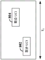
In accordance with various aspects of the present disclosure, to manage individual UCI resource grants for a particular UE, various grant selection rules may be defined to enable the UE to select one or more of the UCI resource grants allocated within a particular time period. For example, referring now to fig. 8, three time periods T are illustrated 1 、T 2 And T 3 . In some examples, each time period T 1 、T 2 And T 3 May include, for example, one or more Transmission Time Intervals (TTIs). As used herein, the term TTI refers to a set comprising one or more OFDM symbols, mini-slots, or slots.
In some examples, as shown in fig. 9, the time period (e.g., time period T) 1 ) Including representation as TTI 1 E.g., the UCI resource grants are allocated within the same TTI). In other examples, the time period (e.g., time period T) 2 ) Comprising two or more overlapping TTIs (TTIs) 2 And TTI 3 ). In yet other examples, the time period (e.g., time period T) 3 ) Including two or more non-overlapping TTIs (e.g., TTIs) 4 And TTI 5 ) From a first transmission time in two or more non-overlapping transmission time intervalsInterval TTI 4 With a second transmission time interval TTI of the two or more non-overlapping transmission time intervals 5 Is determined by the time period between the start and/or end of (a). In the example shown in fig. 9, the period T 3 Is defined as a first transmission time interval TTI 4 With a second transmission time interval TTI 5 The period of time between the end of (c).
Referring again to FIG. 8, at T 1 There are two UCI resource grants 802 and 804, each allocating a respective set of resource elements for UCI (UCI-1 and UCI-2). Although not overlapping in time, UCI resource grants 802 and 804 are included for the same time period T 1 And (4) the following steps. Similarly, at T 2 There are two UCI resource grants 806 and 808, each allocating a respective set of resource elements for UCI (UCI-3 and UCI-4). At T 2 In time, UCI resource grants 806 and 808 partially overlap each other. Also at T 3 There are two UCI resource grants 810 and 812, each allocating a respective set of resource elements for UCI (UCI-4 and UCI-5). At T 3 In, UCI resource grant 810 spans a time period T 3 And the UCI resource grant 812 is completely contained within the UCI resource grant 810.
Thus, at T 1 ,T 2 And T 3 The UE will apply a grant selection rule to select one or more of the UCI resource grants in each time period and transmit UCI on the selected resource elements. E.g. at T 1 In this example, the UE may select UCI resource grants 802 and/or 804 to transmit UCI-1 and/or UCI-2. Furthermore, at T 2 In this case, the UE may select UCI resource grants 806 and/or 808 to transmit UCI-3 and/or UCI-4, and at T 3 The UE may select UCI resource grants 810 and/or 812 to transmit UCI-5 and/or UCI-6.
In some aspects of the disclosure, the UE may be configured with a threshold corresponding to the time period and determine whether a time difference between the first UCI resource grant and the second UCI resource grant is less than the threshold. The time difference may be determined from a start or end of a first UCI resource grant to a start or end of a second UCI resource grant. If the time difference is less than a threshold (e.g., the first and second UCI resource grants occur within the same time period), the UE may select one or both of the UCI resource grants to transmit UCI using a pre-configured grant selection rule.
In some examples, as in fig. 10 (which illustrates time period T of fig. 8) 1 For example) may cause the UE to select each of the UCI resource grants 802 and 804 without modifying either of the UCI resource grants 802 and 804, and transmit UCI assigned to be transmitted by each grant on uplink resources assigned by the grant. For example, the resources allocated for UCI-1 and UCI-2 may each be selected such that UCI-1 may be transmitted on UCI resource grant 802 and UCI-2 may be transmitted on UCI resource grant 804.
In some examples, as in fig. 11 (which illustrates time period T of fig. 8) 1 Another example of (e), the grant selection rule may cause the UE to select at least two of the UCI resource grants and combine the resources allocated to each selected UCI resource grant into a single UCI resource grant. Subsequently, the UE may multiplex UCI for each UCI resource grant within a single UCI resource grant. For example, UCI resource grants 802 and 804 may be combined into a single UCI resource grant 1100, and the UE may multiplex joint UCI (a combination of UCI-1 and UCI-2) across both UCI resource grants 802 and 804. If at least one of the UCI resource grants is a dynamic UCI resource grant, the base station (e.g., the gNB) may need to decode UCI with multiple decoding hypotheses to prevent the UE from being unable to decode DCI including the dynamic UCI resource grant. For example, one decoding hypothesis may decode each UCI resource grant separately, while another decoding hypothesis may decode the combined single UCI resource grant.
A single UCI resource grant may be considered a PUCCH resource grant if the individual UCI resource grants are each PUCCH resource grants. However, if one or more of the individual UCI resource grants is a PUSCH resource grant, a single UCI resource grant may be considered a PUSCH resource grant. Multiplexing UCI on multiple UCI resource grants may provide increased coding gain due to the larger block size. If multiple dynamic UCI resource grants are combined, the DCI for each dynamic UCI resource grant may be received in the same slot or different slots. For example, a dynamic PUCCH grant received in slot n, applied to slot n + k, may be combined with a subsequent PUCCH/PUSCH grant received in slot n + k ', where k' < k.
However, referring again to FIG. 8, if T is the case 3 Where the UCI resource grants shown in (a) overlap in time and FDM or CDM is used for transmission of UCI associated with each UCI resource grant, intermodulation distortion may occur for non-coherent frequency transmissions through the same Power Amplifier (PA). In addition, when a low PAPR waveform (e.g., DFT-s-OFDM waveform) is utilized, the PAPR may also be affected. Thus, in other examples, the grant selection rule may cause the UE to select only one or less than all of the UCI resource grants within the time period, rather than combining the resources allocated for at least two UCI resource grants into a single UCI resource grant.
For example, if during the same time period (e.g., T) 2 Or T 3 ) Intra-partition both a semi-static UCI resource grant for transmitting periodic UCI and a dynamic UCI resource grant for transmitting aperiodic UCI, the grant selection rule may cause the UE to select either the semi-static UCI resource grant or the dynamic UCI resource grant. In some examples, if a semi-static UCI resource grant is selected, the UE may multiplex periodic UCI and at least a portion of aperiodic UCI (associated with the dynamic UCI resource grant) on resources allocated to the semi-static UCI resource grant. Similarly, if a dynamic UCI resource grant is selected, the UE may multiplex both periodic UCI and aperiodic UCI on resources allocated to the dynamic UCI resource grant.
For example, as in fig. 12 (which illustrates the time period T of fig. 8) 1 Another example of (a), if the UCI resource grant 802 corresponds to a semi-static UCI resource grant and the UCI resource grant 804 corresponds to a dynamic UCI resource grant, at least a portion of the aperiodic UCI (UCI-2) that would otherwise be transmitted within the UCI resource grant 804 may be multiplexed with the periodic UCI (UCI-1) transmitted within the UCI resource grant 802. If aperiodic UCI payloadThe load is small enough, all aperiodic and periodic UCI may be multiplexed on the resources allocated to the semi-static UCI resource grant 802. In this example, the base station may again need to utilize multiple decoding hypotheses to prevent the UE from being unable to decode DCI including the dynamic UCI resource grant.
In some examples, rather than the DCI containing a dynamic UCI resource grant indicating specific resources allocated to the dynamic UCI resource grant, the DCI may include a dynamic resource trigger identifying a specific aperiodic UCI to transmit. The dynamic resource trigger may then be used by the UE to determine the particular resources that would otherwise be allocated to the dynamic UCI resource grant (e.g., by using a lookup table or accessing other configuration information, or information about the downlink resources on which the DCI is transmitted). The UE may then further determine that those resources will occur within the same time period as the semi-static uplink resources and multiplex at least a portion of the aperiodic and periodic UCI within the allocated semi-static uplink resources. In other examples, the dynamic resource trigger may simply trigger the UE to transmit at least a portion of the indicated aperiodic UCI within resources allocated to the semi-static UCI resource grant, rather than having the UE determine the particular resources that would otherwise be allocated to the dynamic UCI resource grant. In this way, resources that would otherwise be allocated to the dynamic UCI resource grant may be reassigned by the base station to another UE.
As another example, if the UCI resource grant 804 corresponds to a semi-static UCI resource grant and the UCI resource grant 802 corresponds to a dynamic UCI resource grant, at least a portion of the periodic UCI (UCI-2) that would otherwise be transmitted within the UCI resource grant 804 may be multiplexed with the aperiodic UCI (UCI-1) transmitted within the UCI resource grant 802. In this example, the semi-static resources may be reassigned by the base station to another UE. However, if the UE is unable to decode the dynamic UCI resource grant and transmits on resources allocated to the semi-static UCI resource grant, interference may be generated.
Referring again to fig. 8, in yet other examples, the grant selection rule may cause the UE to select a UCI resource grant that occurs earliest in time (e.g., begins first or ends first) or includes a large UCI resource grant. For example, whileTime period T 2 The UE may select the UCI resource grant 802 because it occurs earlier in time. In some examples, the grant selection rule may cause the UE to select a dynamic UCI resource grant or a semi-static UCI resource grant if there is a connection between UCI resource grants (e.g., each of the UCI resource grants starts or ends at the same time or has the same amount of resources allocated to it).
In some examples, the grant selection rule may cause the UE to select each of the UCI resource grants, combine UCI for each of the selected UCI resource grants, and transmit the combined UCI on each of the UCI resource grants. For example, as in fig. 13 (which illustrates the time period T of fig. 8) 1 Another example of (a), UCI-1 and UCI-2, which were originally transmitted on respective UCI resource grants 802 and 804, respectively, may be combined, and the combined UCI (UCI-1/4) may be transmitted on both UCI resource grants 802 and 804. Thus, UCI is effectively repeated on two or more different PUCCH and/or PUSCH transmissions. Again, the base station may need to utilize multiple decoding hypotheses to prevent the UE from being unable to decode DCI including the dynamic UCI resource grant.
In some examples, as shown in fig. 14 (which illustrates an example of a threshold set equal to a time period of one OFDM symbol), a time difference may be determined between the start and/or end of two UCI resource grants to determine alignment of the start and/or end of the UCI resource grants. For example, the threshold may correspond to a time period T 4 Which is shown to be equal to one OFDM symbol. If the time difference between the respective starts of the two UCI resource grants 814 and 816 is less than a threshold (e.g., T) 4 ) Then the respective starts of UCI resource grants 814 and 816 may be considered to be aligned in time. In this example, the UE may select one of the UCI resource grants 814 and 816 that begin aligning using the preconfigured grant selection rule. In some examples, as described above in connection with fig. 12, the UE may select one of the UCI resource grants (e.g., UCI resource grant 814), combine (e.g., multiplex) at least a portion of the UCI from the UCI resource grant 816 with the UCI for the UCI resource grant, andand transmits the combined UCI on the UCI resource grant 814.
As another example, the threshold may correspond to a time period T 5 Which is shown to be equal to one OFDM symbol. If the time difference between the respective ends of the two UCI resource grants 818 and 820 is less than a threshold (e.g., T) 5 ) Then the respective ends of the UCI resource grants 818 and 820 may be considered to be aligned in time. In this example, the UE may utilize the preconfigured grant selection rule to select one of the ending aligned UCI resource grants 818 and 820. In some examples, as described above in connection with fig. 12, the UE may select one of the UCI resource grants (e.g., UCI resource grant 818), combine (e.g., multiplex) at least a portion of the UCI from UCI resource grant 820 with the UCI for the UCI resource grant, and transmit the combined UCI on the UCI resource grant 818.
As another example, the threshold may include two thresholds, each threshold corresponding to a respective time period T 6 And T 7 Each threshold is shown to be equal to one OFDM symbol. If the time difference between the respective starts of the two UCI resource grants 822 and 824 is less than a first threshold (e.g., T) 6 ) Then the respective starts of the UCI resource grants 822 and 824 may be considered to be aligned in time. Further, if the time difference between the respective ends of the two UCI resource grants 822 and 824 is less than a second threshold (e.g., T) 7 ) Then the respective ends of the UCI resource grants 822 and 824 may be considered to be aligned in time. As such, the two UCI resource grants 822 and 824 may be considered to be perfectly aligned in time. In this example, the UE may utilize the preconfigured grant selection rule to select one of the fully aligned UCI resource grants 822 and 824. In some examples, as described above in connection with fig. 12, the UE may select one of the UCI resource grants (e.g., UCI resource grant 822), combine (e.g., multiplex) at least a portion of the UCI from the UCI resource grant 824 with the UCI for the UCI resource grant 822, and transmit the combined UCI on the UCI resource grant 822.
In various aspects of the disclosure, the grant selection rules may include rules based on various factors. In some examples, the grant selection rule may be based on a payload type and/or a payload size of each of the UCIs. In some examples, the payload type may include a payload priority. For example, an ultra-reliable low latency communication (URLLC) payload may have a higher priority than enhanced mobile broadband (eMBB), and thus the grant selection rule may cause the UE to select an earlier in time grant if the payload conveys information for URLLC traffic (e.g., URLLC uplink user data traffic or acknowledgement information for URLLC downlink user data traffic). As another example, if the semi-static UCI resource grant includes only scheduling requests, the grant selection rule may cause the UE to select a dynamic UCI resource grant and multiplex the scheduling request with the periodic UCI in the dynamic UCI resource grant. As another example, if the semi-static UCI resource grant includes only periodic CQIs while the dynamic UCI resource grant includes feedback information (e.g., ACK/NACK payload), the grant selection rule may cause the UE to select the semi-static UCI and multiplex the ACK/NACK payload with the periodic CQIs for a number of bits (e.g., ≦ N bits) in the semi-static UCI resource grant.
In some examples, the grant selection rule may be based on time resources and/or frequency resources allocated to each of the UCI resource grants. For example, the grant selection rule may cause the UE to refrain from selecting two UCI resource grants within a time period that utilizes FDM and frequency resources in each of the UCI resource grants are separated by more than a number of resource blocks. As another example, the grant selection rule may cause the UE to select the dynamic UCI resource grant or the semi-static UCI resource grant if the dynamic UCI resource grant is later or earlier in time than the semi-static UCI resource grant. In some examples, if the semi-static UCI resource grant includes a scheduling request, delaying transmission of the scheduling request may allow for an opportunity to send an updated near scheduling request (assuming the additional latency is acceptable).
In some examples, the grant selection rule may be based on a waveform type and/or a transmit diversity scheme of each of the UCI resource grants. For example, if FDM is used with a DFT-s-OFDM waveform, the grant selection rule may cause the UE to select only one of the UCI resource grants. As another example, if the UCI resource grants have different transmit diversity schemes, the grant selection rule may cause the UE to select each of the UCI resource grants without modifying any of the UCI resource grants.
The grant selection rules described herein may be applicable to grants for UCI resources located in the same component carrier or different component carriers. Further, the grant selection rule may depend on an index of a component carrier in which the UCI resources are located. For example, component carriers may be divided into groups, and combinations of UCI resources from multiple UCI resource grants may be allowed only for resources located within the same group.
Fig. 15 is a conceptual diagram illustrating an example of a hardware implementation of an exemplary scheduling entity 1500 employing a processing system 1514. For example, the scheduling entity 1500 may be a next generation (5G) base station as illustrated in any one or more of fig. 1 and 2. In another example, the scheduling entity 1500 may be a User Equipment (UE) as illustrated in any one or more of fig. 1 and 2.
The scheduling entity 1500 may be implemented with a processing system 1514 that includes one or more processors 1504. Examples of processor 1504 include microprocessors, microcontrollers, digital Signal Processors (DSPs), field Programmable Gate Arrays (FPGAs), programmable Logic Devices (PLDs), state machines, gating logic, discrete hardware circuits, and other suitable hardware configured to perform the various functionalities described throughout this disclosure. In various examples, scheduling entity 1500 may be configured to perform one or more of the functions described herein. That is, the processor 1504 as utilized in the scheduling entity 1500 may be used to implement any one or more of the processes described below. In some examples, the processor 1504 may be implemented via a baseband or modem chip, and in other implementations, the processor 1504 itself may comprise a number of devices distinct and different from the baseband or modem chip (e.g., in such scenarios the processor 1504 may work consistently to achieve the various embodiments discussed herein). And as mentioned above, various hardware arrangements and components other than baseband modem processors (including RF chains, power amplifiers, modulators, buffers, interleavers, summers/summers, etc.) may be used in implementations.
In this example, the processing system 1514 may be implemented with a bus architecture, represented generally by the bus 1502. The bus 1514 may include any number of interconnecting buses and bridges depending on the specific application of the processing system 1502 and the overall design constraints. The bus 1502 communicatively couples various circuits including one or more processors (represented generally by the processor 1504), memory 1505, and computer-readable media (represented generally by the computer-readable medium 1506). The bus 1502 may also link various other circuits such as timing sources, peripherals, voltage regulators, and power management circuits, which are well known in the art, and therefore, will not be described any further. A bus interface 1508 provides an interface between the bus 1502 and the transceiver 1510. The transceiver 1510 provides a means for communicating with various other apparatus over a transmission medium, such as an air interface. Depending on the nature of the equipment, a user interface 1512 (e.g., keypad, display, speaker, microphone, joystick) may also be provided.
The processor 1504 is responsible for managing the bus 1502 and general processing, including the execution of software stored on the computer-readable medium 1506. The software, when executed by the processor 1504, causes the processing system 1514 to perform the various functions described below for any particular apparatus. The computer-readable medium 1506 and memory 1505 may also be used for storing data that is manipulated by the processor 1504 when executing software.
One or more processors 1504 in the processing system may execute software. Software should be construed broadly to mean instructions, instruction sets, code segments, program code, programs, subprograms, software modules, applications, software packages, routines, subroutines, objects, executables, threads of execution, procedures, functions, etc., whether referred to in software, firmware, middleware, microcode, hardware description language, or other terminology. The software may reside on a computer readable medium 1506.
The computer-readable medium 1506 may be a non-transitory computer-readable medium. By way of example, non-transitory computer-readable media include magnetic storage devices (e.g., hard disks, floppy disks, magnetic tape), optical disks (e.g., compact Disks (CDs) or Digital Versatile Disks (DVDs)), smart cards, flash memory devices (e.g., cards, sticks, or key drives), random Access Memories (RAMs), read Only Memories (ROMs), programmable ROMs (PROMs), erasable PROMs (EPROMs), electrically Erasable PROMs (EEPROMs), registers, removable disks, and any other suitable medium for storing software and/or instructions that may be accessed and read by a computer. By way of example, computer-readable media may also include carrier waves, transmission lines, and any other suitable media for conveying software and/or instructions that are accessible and readable by a computer. The computer-readable medium 1506 may reside in the processing system 1514, external to the processing system 1514, or distributed across multiple entities including the processing system 1514. The computer-readable medium 1506 may be embodied in a computer program product. By way of example, a computer program product may include a computer-readable medium in packaging material. Those skilled in the art will recognize how best to implement the described functionality presented throughout this disclosure, depending on the particular application and the overall design constraints imposed on the overall system.
In some aspects of the disclosure, the processor 1504 may include circuitry configured for various functions. For example, the processor 1504 may include resource assignment and scheduling circuitry 1541 configured to: resource assignments or grants for time-frequency resources (e.g., a set comprising one or more resource elements) are generated, scheduled, and modified. For example, the resource assignment and scheduling circuitry 1541 may schedule time-frequency resources within multiple Time Division Duplex (TDD) and/or Frequency Division Duplex (FDD) subframes, time slots, and/or mini-slots to carry data and/or control information to and/or from multiple UEs (scheduled entities).
In various aspects of the disclosure, the resource assignment and scheduling circuitry 1541 may be configured to: multiple UCI resource grants within a certain time period are scheduled for a single scheduled entity to transmit UCI. Each of the UCI resource grants may be a dynamic UCI resource grant for transmitting aperiodic UCI or may be a semi-static UCI resource grant for transmitting periodic UCI. Resource assignment and scheduling circuitry 1541 may further operate in conjunction with resource assignment and scheduling software 1551.
The processor 1504 may further include Downlink (DL) traffic and control channel generation and transmission circuitry 1542 configured to: downlink user data traffic and control channels are generated and transmitted in one or more subframes, slots, and/or mini-slots. DL traffic and control channel generation and transmission circuitry 1542 may operate in coordination with resource assignment and scheduling circuitry 1541 to place DL user data traffic and/or control information on Time Division Duplex (TDD) or Frequency Division Duplex (FDD) carriers by: DL user data traffic and/or control information is included within one or more subframes, slots, and/or mini-slots according to resources assigned to the DL user data traffic and/or control information.
For example, DL traffic and control channel generation and transmission circuitry 1542 may be configured to: a Physical Downlink Control Channel (PDCCH) (or enhanced PDCCH (ePDCCH)) is generated that includes Downlink Control Information (DCI). In some examples, one or more of the DCIs may include control information indicating a dynamic grant of uplink resources for a scheduled entity to transmit aperiodic UCI. The DL traffic and control channel generation and transmission circuitry 1542 may be further configured to: radio Resource Control (RRC) signaling is generated that includes a semi-persistent grant of uplink resources for a scheduled entity to transmit periodic UCI.
The DL traffic and control channel generation and transmission circuitry 1542 may be further configured to transmit grant selection rules 1515 to one or more scheduled entities. The grant selection rules 1515 may be maintained in, for example, memory 1505. In some examples, the DL traffic and control channel generation and transmission circuitry 1542 may further generate grant selection rules for one or more scheduled entities. In other examples, the grant selection rules 1515 may be preconfigured and stored in the memory 1505. A single set of grant selection rules 1515 may be applicable to any scheduled entity or separate sets of grant selection rules 1515 may be generated for different scheduled entities. For example, each scheduled entity may have a respective set of grant selection rules associated therewith, or each type of scheduled entity (e.g., a scheduled entity sharing a particular characteristic) may have a respective set of grant selection rules associated therewith. The grant selection rules 1515 may be transmitted, for example, within a Master Information Block (MIB), system Information Block (SIB), or other control channel. In other examples, the grant selection rules 1515 may be preconfigured on the scheduling entity 1500 and the scheduled entity, and the particular grant selection rules for the scheduled entity may be determined based on device information associated with the scheduled entity (e.g., particular characteristics of the scheduled entity).
The DL traffic and control channel generation and transmission circuitry 1542 may be further configured to: a Physical Downlink Shared Channel (PDSCH) (or enhanced PDSCH (ePDSCH)) is generated that includes downlink user data traffic. DL traffic and control channel generation and transmission circuitry 1542 may further operate in conjunction with DL traffic and control channel generation and transmission software 1552.
The processor 1504 may further include Uplink (UL) traffic and control channel reception and processing circuitry 1543 configured to: an uplink control channel and an uplink traffic channel are received and processed from one or more scheduled entities. For example, the UL traffic and control channel reception and processing circuitry 1543 may be configured to receive periodic UCI and/or aperiodic UCI on uplink resources allocated to one or more semi-static and/or dynamic UCI resource grants. The UL traffic and control channel reception and processing circuitry 1543 may be further configured to access the grant selection rules 1515 to determine specific UCI resource grants to be selected by a specific scheduled entity during a specific time period. The grant selection rules 1515 may further indicate whether UCI from the individual UCI resource grants may be combined within a single particular UCI resource grant, whether UCI from the individual UCI resource grants may be multiplexed across UCI resource grants, or whether UCI from the individual UCI resource grants may be combined and repeated within each of the UCI resource grants. The UL traffic and control channel reception and processing circuitry 1543 may be further configured to maintain a plurality of decoding hypotheses for the UCI, and apply one or more of the decoding hypotheses to decode the received UCI.
The UL traffic and control channel reception and processing circuitry 1543 may be further configured to: uplink user data traffic is received from one or more scheduled entities. Further, UL traffic and control channel reception and processing circuitry 1543 may operate in conjunction with resource assignment and scheduling circuitry 1541 to schedule UL user data traffic transmissions, DL user data traffic transmissions, and/or DL user data traffic retransmissions in accordance with the received UCI. UL traffic and control channel reception and processing circuitry 1543 may further operate in conjunction with UL traffic and control channel reception and processing software 1553.
Fig. 16 is a conceptual diagram illustrating an example of a hardware implementation of an exemplary scheduled entity 1600 employing a processing system 1614. In accordance with various aspects of the disclosure, an element, or any portion of an element, or any combination of elements may be implemented with a processing system 1614 that includes one or more processors 1604. For example, scheduled entity 1600 may be a User Equipment (UE) as illustrated by any one or more of fig. 1 and 2.
The processing system 1614 may be substantially the same as the processing system 1514 illustrated in fig. 15, including a bus interface 1608, a bus 1602, a memory 1605, a processor 1604, and a computer-readable medium 1606. Further, scheduled entity 1600 may include a user interface 1612 and a transceiver 1610 substantially similar to those described above in fig. 7. That is, the processor 1604 as utilized in the scheduled entity 1600 may be utilized to implement any one or more of the processes described below.
In some aspects of the disclosure, the processor 1604 may comprise Uplink (UL) traffic and control channel generation and transmission circuitry 1641 configured to generate and transmit uplink control/feedback/acknowledgement information on a UL control channel (e.g., PUCCH) or a UL traffic channel (e.g., PUSCH). UL traffic and control channel generation and transmission circuitry 1641 may be further configured to: uplink user data traffic is generated and transmitted on the UL traffic channel (e.g., PUSCH). UL traffic and control channel generation and transmission circuitry 1641 may operate in conjunction with UL traffic and control channel generation and transmission software 1661.
In some examples, the DL traffic and control channel reception and processing circuitry 1642 may be further configured to receive the grant selection rule 1615 from the scheduling entity and store the grant selection rule 1615 within the memory 1605. In other examples, the grant selection rule 1615 may be preconfigured on the scheduled entity 1600 and the scheduling entity. DL traffic and control channel reception and processing circuitry 1642 may operate in conjunction with DL traffic and control channel reception and processing software 1662.
The processor 1604 may further include grant selection and configuration circuitry 1643 configured to manage a plurality of UCI resource grants for the scheduled entity 1600. In some examples, the plurality of UCI resource grants may include one or more semi-static UCI resource grants for periodic UCI and/or one or more dynamic UCI resource grants for aperiodic UCI. The grant selection and configuration circuitry 1643 may be further configured to determine whether two or more UCI resource grants occur within a given time period. For example, the grant selection and configuration circuitry 1643 may access a threshold 16116 maintained, for example, in the memory 1605 and determine whether a time difference between the first UCI resource grant and the second UCI resource grant is less than the threshold. If the time difference is less than a threshold (e.g., the first and second UCI resource grants occur within the same time period), the grant selection and configuration circuitry 1643 may access the grant selection rules 1615 to select one or both of the UCI resources to be ready to transmit UCI. In some examples, the time difference is measured between respective starts and/or respective ends of UCI resource grants.
As described above, in various aspects of the disclosure, the grant selection rules 1615 may include rules based on various factors. In some examples, the grant selection rule may be based on a payload type and/or a payload size of each of the UCIs. The grant selection rules 1615 may be further based on time resources and/or frequency resources allocated to each of the UCI resource grants. The grant selection rules 1615 may be further based on a waveform type and/or a transmit diversity scheme of each of the UCI resource grants.
In some examples, the grant selection rules 1615 may cause the grant selection and configuration circuitry 1643 to select each of the UCI resource grants without modifying any of the UCI resource grants. In other examples, the grant selection rules 1615 may cause the grant selection and configuration circuitry 1643 to select at least two of the UCI resource grants and combine the set of resource elements allocated to each selected UCI resource grant into a single UCI resource grant. The grant selection and configuration circuitry 1643 may then instruct UL traffic and control channel generation and transmission circuitry 1641 to multiplex UCI for each of the UCI resource grants within a single UCI resource grant.
In yet other examples, the grant selection rules 1615 may cause the grant selection and configuration circuitry 1643 to select only one or less than all UCI resource grants among UCI resource grants allocated within a time period. For example, if both semi-static UCI resource grants for transmitting periodic UCI and dynamic UCI resource grants for transmitting aperiodic UCI are allocated during the time period, the grant selection rules 1615 may cause the grant selection and configuration circuitry 1643 to select either the semi-static UCI resource grants or the dynamic UCI resource grants.
If a semi-static UCI resource grant is selected, the grant selection and configuration circuitry 1643 may instruct UL traffic and control channel generation and transmission circuitry 1641 to multiplex periodic UCI and at least a portion of aperiodic UCI on resources allocated to the semi-static UCI resource grant. If a dynamic UCI resource grant is selected, the grant selection and configuration circuitry 1643 may instruct UL traffic and control channel generation and transmission circuitry 1641 to multiplex both periodic UCI and dynamic UCI on resources allocated to the dynamic UCI resource grant.
In still other examples, the grant selection rules 1615 may cause the grant selection and configuration circuitry 1643 to select the UCI resource grant that occurs earliest in time (e.g., begins first or ends first) or includes the largest set of resources. In some examples, if there is a connection between UCI resource grants (e.g., each of the UCI resource grants starts or ends at the same time, or has the same amount of resources allocated thereto), the grant selection rules 1615 may cause the grant selection and configuration circuitry 1643 to select a dynamic UCI resource grant or a semi-static UCI resource grant. As indicated above, then the periodic UCI and the aperiodic UCI may be multiplexed.
In yet other examples, the grant selection rules 1615 may cause the grant selection and configuration circuitry 1643 to select each of the UCI resource grants. The grant selection and configuration circuitry 1643 may then instruct UL traffic and control channel generation and transmission circuitry 1641 to combine UCI for each of the selected UCI resource grants and transmit the combined UCI on each of the selected UCI resource grants. The grant selection and configuration circuitry 1643 may operate in conjunction with grant selection and configuration software 1663.
Fig. 17 is a diagram illustrating an example of a Physical Downlink Control Channel (PDCCH) 1700 carrying control information. As shown in fig. 17, PDCCH 1700 may include a plurality of Downlink Channel Information (DCI) 1010 (e.g., DCI-1 … DCI-N). Each DCI 1710 may include scheduling assignments (e.g., downlink assignments and/or uplink grants) for one or more scheduled entities.
In the example shown in fig. 17, PDCCH 1700 includes multiple DCIs 1710 for a single UE (e.g., UE 1). For example, DCI-1 may include a semi-static (e.g., SPS) UCI resource grant for UE1, while DCI-2 may include a dynamic UCI resource grant for UE 1. As such, DCI-1 and DCI-2 may each include respective scheduling information indicating a set of one or more resource elements (e.g., time-frequency resources) allocated for the UCI resource grant. Furthermore, DCI-1 may each further include SPS configuration parameters for SPS UCI resource grants. The additional DCI 1710 within PDCCH 1700 or a subsequent PDCCH may include activation of an SPS UCI resource grant to enable UE1 to begin utilizing the SPS UCI resource grant based on SPS configuration parameters for the SPS UCI resource grant. To disable/release the SPS UCI resource grant, the subsequent PDCCH may include a DCI including explicit disabling/release of the SPS UCI resource grant.
Although multiple uplink grants are illustrated in fig. 17 as being included within a single PDCCH, it should be understood that different uplink grants for UE1 may be included in two or more PDCCHs. For example, an SPS UCI resource grant may be included in one PDCCH, while a dynamic UCI resource grant is included in another PDCCH.
In some examples, DCI-1 or DCI-2 may include a resource trigger identifying a particular UCI to transmit, rather than DCI-1 or DCI-2 indicating the particular resources allocated to the UCI resource grant. In some examples, the resource trigger may then be used by the UE to determine the particular uplink resources that would otherwise be allocated to the UCI resource grant (e.g., by using a lookup table or accessing other configuration information, or information about the downlink resources on which the DCI is transmitted).
Fig. 18 is a flow diagram illustrating an example process 1800 for managing multiple Uplink Control Information (UCI) resource grants to transmit UCI in a wireless communication network, in accordance with some aspects of the present disclosure. As described below, some or all of the illustrated features may be omitted in particular implementations within the scope of the disclosure, and some of the illustrated features may not be required for implementation of all embodiments. In some examples, process 1800 may be performed by a scheduled entity illustrated in fig. 16. In some examples, process 1800 may be performed by any suitable equipment or means for performing the functions or algorithms described below.
At block 1802, a scheduled entity may receive a first UCI resource grant that allocates a first set of resource elements used by the scheduled entity to transmit first Uplink Control Information (UCI). For example, the first UCI resource grant may be a dynamic UCI resource grant for aperiodic UCI, e.g., received within a PDCCH. As another example, the first UCI resource grant may be a semi-static UCI resource grant for periodic UCI, e.g., received within a PDCCH and configured via higher layer (e.g., RRC) signaling. At block 1804, the scheduled entity may receive a second UCI resource grant that allocates a second set of resource elements used by the scheduled entity to transmit a second UCI. For example, the second UCI resource grant may be a dynamic UCI resource grant for aperiodic UCI, e.g., received within a PDCCH. As another example, the second UCI resource grant may be a semi-static UCI resource grant for periodic UCI, e.g., received within a PDCCH and configured via higher layer (e.g., RRC) signaling. For example, the DL traffic and control channel reception and processing circuitry 1642 shown and described above with reference to fig. 16 may receive the first and second UCI resource grants.
At block 1806, the scheduled entity may determine whether a Time Difference (TD) between a first set of resource elements for the first UCI resource grant and a second resource element for the second UCI resource grant is less than a threshold. The time difference may be determined from a start or end of a first UCI resource grant to a start or end of a second UCI resource grant. Further, the threshold may include at least one transmission time interval, each transmission time interval corresponding to a set of one or more Orthogonal Frequency Division Multiplexing (OFDM) symbols, a mini-slot, a slot, or a set of two or more slots. In some examples, the threshold may include a single transmission time interval, two overlapping transmission time intervals, or two non-overlapping transmission time intervals. For example, the grant selection and configuration circuitry 1643 shown and described above with reference to fig. 16 may determine a time difference between UCI resource grants.
If the time difference between the resource elements of the UCI resource grants is less than a threshold (Y branch of block 1806), the scheduled entity may select at least one UCI resource grant of the UCI resource grants at block 1808 based on one or more grant selection rules. In some examples, the scheduled entity may select two UCI resource grants without modifying any UCI resource grants. In other examples, the scheduled entity may select two UCI resource grants and combine the set of resource elements allocated to each selected UCI resource grant into a single UCI resource grant on which UCI may be multiplexed, or combine each of the UCI resource grants for the UCI resource grants and transmit the combined UCI separately on each of the set of resource elements of the UCI resource grant. In yet another example, the scheduled entity may select only one of the UCI resource grants and multiplex all or a portion of the UCI within the selected UCI resource grant. For example, the grant selection and configuration circuitry 1643 shown and described above with reference to fig. 16 may select at least one of the UCI resource grants.
Fig. 19 is a flow diagram illustrating an example process 1900 for managing multiple Uplink Control Information (UCI) resource grants to transmit UCI in a wireless communication network, in accordance with some aspects of the present disclosure. As described below, some or all of the illustrated features may be omitted in particular implementations within the scope of the present disclosure, and some of the illustrated features may not be required for implementation of all embodiments. In some examples, process 1900 may be performed by a scheduled entity illustrated in fig. 16. In some examples, process 1900 may be performed by any suitable equipment or means for performing the functions or algorithms described below.
At block 1902, a scheduled entity may receive a first UCI resource grant allocating a first set of resource elements used by the scheduled entity to transmit first Uplink Control Information (UCI). For example, the first UCI resource grant may be a dynamic UCI resource grant for aperiodic UCI, e.g., received within a PDCCH. As another example, the first UCI resource grant may be a semi-static UCI resource grant for periodic UCI, e.g., received within a PDCCH and configured via higher layer (e.g., RRC) signaling. At block 1904, the scheduled entity may receive a second UCI resource grant that allocates a second set of resource elements used by the scheduled entity to transmit a second UCI. For example, the second UCI resource grant may be a dynamic UCI resource grant for aperiodic UCI, e.g., received within a PDCCH. As another example, the second UCI resource grant may be a semi-static UCI resource grant for periodic UCI, e.g., received within a PDCCH and configured via higher layer (e.g., RRC) signaling. For example, the DL traffic and control channel reception and processing circuitry 1642 shown and described above with reference to fig. 16 may receive the first and second UCI resource grants.
At block 1906, the scheduled entity may determine whether a Time Difference (TD) between a first set of resource elements for the first UCI resource grant and a second resource element for the second UCI resource grant is less than a threshold. The time difference may be determined from a start or end of a first UCI resource grant to a start or end of a second UCI resource grant. Further, the threshold may include at least one transmission time interval, each transmission time interval corresponding to a set of two or more orthogonal frequency division multiplexing symbols, a mini-slot, a timeslot, or a set of two or more timeslots. In some examples, the threshold may include a single transmission time interval, two overlapping transmission time intervals, or two non-overlapping transmission time intervals. For example, the grant selection and configuration circuitry 1643 shown and described above with reference to fig. 16 may determine a time difference between UCI resource grants.
If the time difference between the resource elements of the UCI resource grant is less than the threshold (Y branch of block 1806), the scheduled entity may combine the first set of resource elements and the second set of resource elements to produce a combined set of resource elements at block 1808. For example, the grant selection and configuration circuitry 1643 shown and described above with reference to fig. 16 may combine the set of resource elements from each of the UCI resource grants based on a grant selection rule to produce a combined set of resource elements.
At block 1810, the scheduled entity may multiplex the first UCI and the second UCI on the combined set of resource elements. The combined UCI resource grant may be considered a PUCCH resource grant if the individual UCI resource grants are each PUCCH resource grants. However, if one or more of the individual UCI resource grants is a PUSCH resource grant, the combined UCI resource grant may be considered a PUSCH resource grant. For example, UL traffic and control channel reception and processing circuitry 1641 shown and described above with reference to fig. 16 may multiplex UCI across the combined set of resource elements.
Fig. 20 is a flow diagram illustrating an example process 2000 for managing multiple Uplink Control Information (UCI) resource grants to transmit UCI in a wireless communication network, in accordance with some aspects of the present disclosure. As described below, some or all of the illustrated features may be omitted in particular implementations within the scope of the present disclosure, and some of the illustrated features may not be required for implementation of all embodiments. In some examples, process 2000 may be performed by the scheduled entity illustrated in fig. 16. In some examples, process 2000 may be performed by any suitable equipment or means for performing the functions or algorithms described below.
At block 2002, a scheduled entity may receive a semi-static UCI resource grant that allocates a first set of resource elements for use by the scheduled entity to transmit periodic Uplink Control Information (UCI). For example, a semi-static UCI resource grant may be received, e.g., within a PDCCH and configured via higher layer (e.g., RRC) signaling. At block 2004, the scheduled entity may receive a dynamic UCI resource grant that allocates a second set of resource elements used by the scheduled entity to transmit aperiodic UCI. For example, a dynamic UCI resource grant may be received, e.g., within a PDCCH. For example, the DL traffic and control channel receive and processing circuitry 1642 shown and described above with reference to fig. 16 may receive semi-static and dynamic UCI resource grants.
At block 2006, the scheduled entity may determine whether a Time Difference (TD) between a first set of resource elements for the semi-static UCI resource grant and a second resource element for the dynamic UCI resource grant is less than a threshold. The time difference may be determined from a start or end of a first UCI resource grant to a start or end of a second UCI resource grant. Further, the threshold may include at least one transmission time interval, each transmission time interval corresponding to a set of two or more orthogonal frequency division multiplexing symbols, a mini-slot, a timeslot, or a set of two or more timeslots. In some examples, the threshold may include a single transmission time interval, two overlapping transmission time intervals, or two non-overlapping transmission time intervals. For example, the grant selection and configuration circuitry 1643 shown and described above with reference to fig. 16 may determine a time difference between UCI resource grants.
If the time difference between the resource elements of the UCI resource grant is less than the threshold (Y branch of block 2006), the scheduled entity may select a semi-static UCI resource grant at block 2008. In some examples, the dynamic UCI resource grant includes a dynamic resource trigger identifying aperiodic uplink control information, the dynamic resource trigger triggering selection of a periodic UCI resource grant. For example, the grant selection and configuration circuitry 1643 shown and described above with reference to fig. 16 may select a semi-static UCI resource grant based on a grant selection rule.
At block 2010, a scheduled entity may multiplex a periodic UCI and at least a portion of an aperiodic UCI on a first set of resource elements. In some examples, the dynamic resource trigger within the periodic UCI resource grant triggers multiplexing of periodic uplink control information and at least a portion of aperiodic uplink control information over the first set of resource elements. For example, UL traffic and control channel generation and transmission circuitry 1641 shown and described above with reference to fig. 16 may multiplex periodic UCI and at least a portion of aperiodic UCI on a first set of resource elements.
Fig. 21 is a flow diagram illustrating an example process 2100 for managing multiple Uplink Control Information (UCI) resource grants to transmit UCI in a wireless communication network in accordance with some aspects of the present disclosure. As described below, some or all of the illustrated features may be omitted in particular implementations within the scope of the present disclosure, and some of the illustrated features may not be required for implementation of all embodiments. In some examples, process 2100 may be performed by a scheduled entity illustrated in fig. 16. In some examples, process 2100 may be performed by any suitable equipment or means for performing the functions or algorithms described below.
At block 2102, a scheduled entity may receive a semi-static UCI resource grant that allocates a first set of resource elements for use by the scheduled entity to transmit periodic Uplink Control Information (UCI). For example, a semi-static UCI resource grant may be received, e.g., within a PDCCH and configured via higher layer (e.g., RRC) signaling. At block 2104, the scheduled entity may receive a dynamic UCI resource grant that allocates a second set of resource elements used by the scheduled entity to transmit aperiodic UCI. For example, a dynamic UCI resource grant may be received, e.g., within a PDCCH. For example, the DL traffic and control channel reception and processing circuitry 1642 shown and described above with reference to fig. 16 may receive semi-static and dynamic UCI resource grants.
At block 2106, the scheduled entity may determine whether a Time Difference (TD) between a first set of resource elements for the semi-static UCI resource grant and a second resource element for the dynamic UCI resource grant is less than a threshold. The time difference may be determined from a start or end of a first UCI resource grant to a start or end of a second UCI resource grant. Further, the threshold may include at least one transmission time interval, each transmission time interval corresponding to a set of two or more orthogonal frequency division multiplexing symbols, a mini-slot, a timeslot, or a set of two or more timeslots. In some examples, the threshold may include a single transmission time interval, two overlapping transmission time intervals, or two non-overlapping transmission time intervals. For example, the grant selection and configuration circuitry 1643 shown and described above with reference to fig. 16 may determine a time difference between UCI resource grants.
If the time difference between the resource elements of the UCI resource grant is less than the threshold (Y branch of block 2106), the scheduled entity may select a dynamic UCI resource grant at block 2108. For example, the grant selection and configuration circuitry 1643 shown and described above with reference to fig. 16 may select a dynamic UCI resource grant based on a grant selection rule.
At block 2110, the scheduled entity may multiplex the aperiodic UCI and at least a portion of the periodic UCI on a second set of resource elements. For example, UL traffic and control channel generation and transmission circuitry 1641 illustrated and described above with reference to fig. 16 may multiplex aperiodic UCI and at least a portion of periodic UCI on a first set of resource elements.
Fig. 22 is a flow diagram illustrating an example process 2200 for managing multiple Uplink Control Information (UCI) resource grants to a scheduled entity to receive UCI in a wireless communication network, in accordance with some aspects of the present disclosure. As described below, some or all of the illustrated features may be omitted in particular implementations within the scope of the disclosure, and some of the illustrated features may not be required for implementation of all embodiments. In some examples, process 2200 may be implemented by a scheduling entity illustrated in fig. 15. In some examples, process 2200 may be performed by any suitable equipment or means for performing the functions or algorithms described below.
At block 2202, a scheduling entity may transmit a first UCI resource grant that allocates a first set of resource elements used by a scheduled entity to transmit first Uplink Control Information (UCI). For example, the first UCI resource grant may be a dynamic UCI resource grant for aperiodic UCI, e.g., transmitted within a PDCCH. As another example, the first UCI resource grant may be a semi-static UCI resource grant for periodic UCI, e.g., transmitted within a PDCCH and configured via higher layer (e.g., RRC) signaling. At block 2204, the scheduling entity may transmit a second UCI resource grant that allocates a second set of resource elements used by the scheduled entity to transmit the second UCI. For example, the second UCI resource grant may be a dynamic UCI resource grant for aperiodic UCI, e.g., transmitted within a PDCCH. As another example, the second UCI resource grant may be a semi-static UCI resource grant for periodic UCI, e.g., transmitted within a PDCCH and configured via higher layer (e.g., RRC) signaling. For example, the resource assignment and scheduling circuitry 1541 and DL traffic and control channel generation and transmission circuitry 1542 shown and described above with reference to fig. 15 may generate and transmit first and second UCI resource grants.
At block 2206, the scheduling entity may identify which of the first and/or second UCI resource grants the scheduled entity is to select based on a grant selection rule maintained by the scheduling entity and the scheduled entity. In some examples, the scheduling entity may generate and transmit the grant selection rule to the scheduled entity. In other examples, the grant selection rules may be preconfigured and stored on the scheduling entity and the scheduled entity. In some examples, the scheduling entity may determine that the scheduled entity is to select two UCI resource grants without modifying any UCI resource grants. In other examples, the scheduling entity may determine that the scheduled entity is to select two UCI resource grants and combine the set of resource elements allocated to each selected UCI resource grant into a single UCI resource grant on which UCI may be multiplexed, or combine each of the UCI resource grants for the UCI resource grants and transmit the combined UCI separately on each of the set of resource elements of the UCI resource grant. In yet another example, the scheduling entity may determine that the scheduled entity is to select only one of the UCI resource grants and multiplex all or a portion of the UCI within the selected UCI resource grant. For example, the UL traffic and control channel reception and processing circuitry 1543 shown and described above with reference to fig. 15 may identify the selected UCI resource grant.
At block 2208, the scheduling entity may receive the first and/or second UCI for the selected UCI resource grant(s) from the scheduled entity. In some examples, the scheduling entity may maintain a plurality of decoding hypotheses for the UCI and apply one or more of the decoding hypotheses to decode the received UCI. For example, the UL traffic and control channel reception and processing circuitry 1543 shown and described above with reference to fig. 15 may receive UCI from the scheduled entity regarding the selected UCI resource grant(s).
In one configuration, a scheduled entity (e.g., a UE) in wireless communication with a scheduling entity in a wireless communication network comprises: the apparatus generally includes means for receiving a first Uplink Control Information (UCI) resource grant allocating a first set of resource elements used by a scheduled entity to transmit first uplink control information to a scheduling entity, means for receiving a second UCI resource grant allocating a second set of resource elements used by the scheduled entity to transmit second uplink control information to the scheduling entity, and means for selecting at least one of the first UCI resource grant or the second UCI resource grant based on one or more grant selection rules when a time difference between the first set of resource elements and the second set of resource elements is less than a threshold indicating that the first UCI resource grant and the second UCI resource grant occurred within a same time period, wherein the threshold corresponds to the time period.
In one aspect, the aforementioned means for receiving first and second UCI resource grants and selecting at least one of the UCI resource grants may be the processor(s) 1604 shown in fig. 16 configured to perform the functions recited by the aforementioned means. For example, the aforementioned means for receiving first and second UCI resource grants may comprise DL traffic and control channel generation and transmission circuitry 1641 shown in fig. 16. As another example, the aforementioned means for selecting at least one of the UCI resource grants may comprise grant selection and configuration circuitry 1643 shown in fig. 16. In another aspect, the aforementioned means for communicating may be the transceiver 1610 and the processor(s) 1604 shown in fig. 16 configured to perform the functions recited by the aforementioned means. In yet another aspect, the aforementioned means may be circuitry or any apparatus configured to perform the functions recited by the aforementioned means.
Several aspects of a wireless communication network have been presented with reference to exemplary implementations. As those skilled in the art will readily appreciate, the various aspects described throughout this disclosure may be extended to other telecommunications systems, network architectures, and communication standards.
By way of example, the various aspects may be implemented within other systems defined by 3GPP, such as Long Term Evolution (LTE), evolved Packet System (EPS), universal Mobile Telecommunications System (UMTS), and/or Global System for Mobile (GSM). The various aspects may also be extended to systems defined by third generation partnership project 2 (3 GPP 2), such as CDMA2000 and/or evolution-data optimized (EV-DO). Other examples may be implemented within systems employing IEEE 802.11 (Wi-Fi), IEEE 802.16 (WiMAX), IEEE 802.20, ultra Wideband (UWB), bluetooth, and/or other suitable systems. The actual telecommunications standard, network architecture, and/or communication standard employed will depend on the specific application and the overall design constraints imposed on the system.
Within this disclosure, the word "exemplary" is used to mean "serving as an example, instance, or illustration. Any implementation or aspect described herein as "exemplary" is not necessarily to be construed as preferred or advantageous over other aspects of the disclosure. Likewise, the term "aspect" does not require that all aspects of the disclosure include the discussed feature, advantage or mode of operation. The term "coupled" is used herein to refer to a direct or indirect coupling between two objects. For example, if object a physically contacts object B, and object B contacts object C, objects a and C may still be considered to be coupled to each other even though they are not in direct physical contact with each other. For example, a first object may be coupled to a second object even though the first object is never in direct physical contact with the second object. The terms "circuit" and "circuitry" are used broadly and are intended to include both hardware implementations of electronic devices and conductors that when connected and configured enable the functions described in this disclosure to be performed, without limitation as to the type of electronic circuitry, and software implementations of information and instructions that when executed by a processor enable the functions described in this disclosure to be performed.
One or more of the components, steps, features, and/or functions illustrated in fig. 1-22 may be rearranged and/or combined into a single component, step, feature, or function or may be implemented in several components, steps, or functions. Additional elements, components, steps, and/or functions may also be added without departing from the novel features disclosed herein. The apparatus, devices, and/or components illustrated in fig. 1, 2, 15, and/or 16 may be configured to perform one or more of the methods, features, or steps described herein. The novel algorithms described herein may also be efficiently implemented in software and/or embedded in hardware.
It is to be understood that the specific order or hierarchy of steps in the methods disclosed is an illustration of exemplary processes. Based upon design preferences, it is understood that the specific order or hierarchy of steps in the methods may be rearranged. The accompanying method claims present elements of the various steps in a sample order, and are not meant to be limited to the specific order or hierarchy presented unless specifically recited herein.
Claims (50)
1. A method of wireless communication in a wireless communication network, the method comprising, at a scheduled entity:
receiving a first Uplink Control Information (UCI) resource grant that allocates a first set of resource elements used by the scheduled entity to transmit first uplink control information to a scheduling entity;
receiving a second UCI resource grant allocating a second set of resource elements used by the scheduled entity to transmit second uplink control information to the scheduling entity;
in response to a time difference between the first set of resource elements and the second set of resource elements being less than a threshold indicating that the first UCI resource grant and the second UCI resource grant occurred within a same time period, combining the first set of resource elements for the first UCI resource grant with the second set of resource elements for the second UCI resource grant to generate a combined set of resource elements, wherein the threshold corresponds to the time period; and
multiplexing the first uplink control information and the second uplink control information on the combined set of resource elements.
2. The method of claim 1, wherein the threshold comprises at least one transmission time interval, each transmission time interval corresponding to a set of one or more Orthogonal Frequency Division Multiplexing (OFDM) symbols, a mini-slot, a slot, or a set of two or more slots.
3. The method of claim 2, wherein the at least one transmission time interval comprises a single transmission time interval, two overlapping transmission time intervals, or two non-overlapping transmission time intervals.
4. The method of claim 3, wherein the at least one transmission time interval comprises the two non-overlapping transmission time intervals, and the threshold is equal to a maximum time period between a start or end of a first transmission time interval of the two non-overlapping transmission time intervals and a start or end of a second transmission time interval of the two non-overlapping transmission time intervals.
5. The method of claim 2, wherein:
the time difference is between a start of the first UCI resource grant and a start of the second UCI resource grant;
the threshold corresponding to the time period is equal to a single OFDM symbol; and is
The method further comprises;
select at least one of the first UCI resource grant or the second UCI resource grant based on one or more grant selection rules when the time difference is less than the single OFDM symbol such that a start of the first UCI resource grant and a start of the second UCI resource grant are aligned in time.
6. The method of claim 2, wherein:
the time difference is between an end of the first UCI resource grant and an end of the second UCI resource grant;
the threshold corresponding to the time period is equal to a single OFDM symbol; and is
The method further comprises;
select at least one of the first UCI resource grant or the second UCI resource grant based on one or more grant selection rules when the time difference is less than the single OFDM symbol such that an end of the first UCI resource grant and an end of the second UCI resource grant are aligned in time.
7. The method of claim 2, wherein:
the time difference comprises a first time difference between a start of the first UCI resource grant and a start of a second UCI resource grant, and a second time difference between an end of the first UCI resource grant and an end of the second UCI resource grant;
the threshold corresponding to the time period is equal to a single OFDM symbol; and is
The method further comprises;
select at least one of the first UCI resource grant or the second UCI resource grant based on one or more grant selection rules when the first time difference is less than the single OFDM symbol and the second time difference is less than the single OFDM symbol such that ends of the first UCI resource grant and the second UCI resource grant are fully aligned in time.
8. The method of claim 1, wherein the combined set of resource elements comprises PUCCH resources when the first UCI resource grant comprises a first Physical Uplink Control Channel (PUCCH) grant and the second UCI resource grant comprises a second PUCCH grant.
9. The method of claim 1, wherein the combined set of resource elements comprises a Physical Uplink Shared Channel (PUSCH) grant when at least one of the first UCI resource grant or the second UCI resource grant comprises a PUSCH grant.
10. A method of wireless communication in a wireless communication network, the method comprising, at a scheduled entity:
receiving a first Uplink Control Information (UCI) resource grant that allocates a first set of resource elements used by the scheduled entity to transmit first uplink control information to a scheduling entity, wherein the first UCI resource grant comprises a semi-static UCI resource grant, the first uplink control information comprising periodic uplink control information;
receiving a second UCI resource grant that allocates a second set of resource elements used by the scheduled entity to transmit second uplink control information to the scheduling entity, wherein the second UCI resource grant comprises a dynamic UCI resource grant and the second uplink control information comprises aperiodic uplink control information; and
in response to a time difference between the first set of resource elements and the second set of resource elements being less than a threshold indicating that the first UCI resource grant and the second UCI resource grant occur within a same time period, select at least one of the first UCI resource grant or the second UCI resource grant based on one or more grant selection rules, wherein the threshold corresponds to the time period.
11. The method of claim 10, wherein selecting at least one of the first UCI resource grant or the second UCI resource grant further comprises:
selecting the semi-static UCI resource grant; and
multiplexing the periodic uplink control information and at least a portion of the aperiodic uplink control information on the first set of resource elements.
12. The method of claim 11, wherein:
the dynamic UCI resource grant includes a dynamic resource trigger identifying the aperiodic uplink control information; and
multiplexing the periodic uplink control information and at least a portion of the aperiodic uplink control information on the first set of resource elements is triggered by the dynamic resource trigger.
13. The method of claim 10, wherein selecting at least one of the first UCI resource grant or the second UCI resource grant further comprises:
selecting the dynamic UCI resource grant; and
multiplexing the aperiodic uplink control information and at least a portion of the periodic uplink control information on the second set of resource elements.
14. The method of claim 10, wherein selecting at least one of the first UCI resource grant or the second UCI resource grant further comprises:
selecting one of the semi-static UCI resource grant or the dynamic UCI resource grant that occurs earlier in time or comprises a larger set of resources.
15. A method of wireless communication in a wireless communication network, the method comprising, at a scheduled entity:
receiving a first Uplink Control Information (UCI) resource grant that allocates a first set of resource elements used by the scheduled entity to transmit first uplink control information to a scheduling entity;
receiving a second UCI resource grant allocating a second set of resource elements used by the scheduled entity to transmit second uplink control information to the scheduling entity;
in response to a time difference between the first set of resource elements and the second set of resource elements being less than a threshold value indicating that the first and second UCI resource grants occur within a same time period, selecting both the first and second UCI resource grants, wherein the threshold value corresponds to the time period;
transmitting the first uplink control information and the second uplink control information on the first set of resource elements; and
transmitting the first uplink control information and the second uplink control information on the second set of resource elements.
16. A method of wireless communication in a wireless communication network, the method comprising, at a scheduled entity:
receiving a first Uplink Control Information (UCI) resource grant that allocates a first set of resource elements used by the scheduled entity to transmit first uplink control information to a scheduling entity;
receiving a second UCI resource grant allocating a second set of resource elements used by the scheduled entity to transmit second uplink control information to the scheduling entity;
in response to a time difference between the first set of resource elements and the second set of resource elements being less than a threshold indicating that the first UCI resource grant and the second UCI resource grant occur within a same time period, select at least one of the first UCI resource grant or the second UCI resource grant based on one or more grant selection rules, wherein the threshold corresponds to the time period, and
wherein the one or more grant selection rules are based on at least one of: a payload type of at least one of the first uplink control information or the second uplink control information, a payload size of at least one of the first uplink control information or the second uplink control information, a waveform type of at least one of the first UCI resource grant or the second UCI resource grant, a transmit diversity scheme of at least one of the first UCI resource grant or the second UCI resource grant, time resources utilized by at least one of the first set of resource elements or the second set of resource elements, or frequency resources utilized by at least one of the first set of resource elements or the second set of resource elements, or some combination thereof.
17. A scheduled entity in wireless communication with a scheduling entity in a wireless communication network, comprising:
a processor;
a transceiver communicatively coupled to the processor; and
a memory communicatively coupled to the processor, wherein the processor is configured to:
receiving, via the transceiver, a first Uplink Control Information (UCI) resource grant that allocates a first set of resource elements used by the scheduled entity to transmit first uplink control information to the scheduling entity;
receiving, via the transceiver, a second UCI resource grant that allocates a second set of resource elements used by the scheduled entity to transmit second uplink control information to the scheduling entity;
in response to a time difference between the first set of resource elements and the second set of resource elements being less than a threshold indicating that the first UCI resource grant and the second UCI resource grant occurred within a same time period, combining the first set of resource elements for the first UCI resource grant with the second set of resource elements for the second UCI resource grant to produce a combined set of resource elements, wherein the threshold corresponds to the time period; and
multiplexing the first uplink control information and the second uplink control information on the combined set of resource elements.
18. The scheduled entity of claim 17, wherein the threshold comprises at least one transmission time interval, each transmission time interval corresponding to a set of one or more Orthogonal Frequency Division Multiplexing (OFDM) symbols, a mini-slot, a slot, or a set of two or more slots.
19. The scheduled entity of claim 18, wherein the at least one transmission time interval comprises a single transmission time interval, two overlapping transmission time intervals, or two non-overlapping transmission time intervals.
20. The scheduled entity of claim 19, wherein the at least one transmission time interval comprises the two non-overlapping transmission time intervals, and the threshold is equal to a maximum time period between a start or end of a first transmission time interval of the two non-overlapping transmission time intervals and a start or end of a second transmission time interval of the two non-overlapping transmission time intervals.
21. The scheduled entity of claim 18, wherein:
the time difference is between a start of the first UCI resource grant and a start of the second UCI resource grant;
the threshold corresponding to the time period is equal to a single OFDM symbol; and is
The processor is further configured to:
select at least one of the first UCI resource grant or the second UCI resource grant based on one or more grant selection rules when the time difference is less than the single OFDM symbol such that a start of the first UCI resource grant and a start of the second UCI resource grant are aligned in time.
22. The scheduled entity of claim 18, wherein:
the time difference is between an end of the first UCI resource grant and an end of the second UCI resource grant;
the threshold corresponding to the time period is equal to a single OFDM symbol; and is
The processor is further configured to:
select at least one of the first UCI resource grant or the second UCI resource grant based on one or more grant selection rules when the time difference is less than the single OFDM symbol such that an end of the first UCI resource grant and an end of the second UCI resource grant are aligned in time.
23. The scheduled entity of claim 18, wherein:
the time difference comprises a first time difference between a start of the first UCI resource grant and a start of a second UCI resource grant, and a second time difference between an end of the first UCI resource grant and an end of the second UCI resource grant;
the threshold corresponding to the time period is equal to a single OFDM symbol; and is
The processor is further configured to:
selecting at least one of the first UCI resource grant or the second UCI resource grant based on one or more grant selection rules when the first time difference is less than the single OFDM symbol and the second time difference is less than the single OFDM symbol such that ends of the first UCI resource grant and the second UCI resource grant are fully aligned in time.
24. The scheduled entity of claim 17, wherein the combined set of resources comprises PUCCH resources when the first UCI resource grant comprises a first Physical Uplink Control Channel (PUCCH) grant and the second UCI resource grant comprises a second PUCCH grant.
25. The scheduled entity of claim 17, wherein the combined set of resources comprises a Physical Uplink Shared Channel (PUSCH) grant when at least one of the first UCI resource grant or the second UCI resource grant comprises a PUSCH grant.
26. A scheduled entity in wireless communication with a scheduling entity in a wireless communication network, comprising:
a processor;
a transceiver communicatively coupled to the processor; and
a memory communicatively coupled to the processor, wherein the processor is configured to:
receiving, via the transceiver, a first Uplink Control Information (UCI) resource grant that allocates a first set of resource elements used by the scheduled entity to transmit first uplink control information to the scheduling entity;
receiving, via the transceiver, a second UCI resource grant that allocates a second set of resource elements used by the scheduled entity to transmit second uplink control information to the scheduling entity; and
in response to a time difference between the first set of resource elements and the second set of resource elements being less than a threshold indicating that the first UCI resource grant and the second UCI resource grant occur within a same time period, selecting at least one of the first UCI resource grant or the second UCI resource grant based on one or more grant selection rules, wherein the threshold corresponds to the time period, and wherein the first UCI resource grant includes a semi-static UCI resource grant, the first uplink control information includes periodic uplink control information, the second UCI resource grant includes dynamic UCI resource grants, and the second uplink control information includes uplink control information.
27. The scheduled entity of claim 26, wherein the processor is further configured to:
selecting the semi-static UCI resource grant; and
multiplexing the periodic uplink control information and at least a portion of the aperiodic uplink control information on the first set of resource elements.
28. The scheduled entity of claim 26, wherein:
the dynamic UCI resource grant includes a dynamic resource trigger identifying the aperiodic uplink control information; and
the processor is further configured to multiplex the periodic uplink control information and at least a portion of the aperiodic uplink control information on the first set of resource elements based on the dynamic resource trigger.
29. The scheduled entity of claim 26, wherein the processor is further configured to:
selecting the dynamic UCI resource grant; and
multiplexing the periodic uplink control information and the aperiodic uplink control information on the second set of resource elements.
30. The scheduled entity of claim 26, wherein the processor is further configured to:
selecting one of the semi-static UCI resource grant or the dynamic UCI resource grant that occurs earlier in time or comprises a larger set of resources.
31. A scheduled entity in wireless communication with a scheduling entity in a wireless communication network, comprising:
a processor;
a transceiver communicatively coupled to the processor; and
a memory communicatively coupled to the processor, wherein the processor is configured to:
receiving, via the transceiver, a first Uplink Control Information (UCI) resource grant that allocates a first set of resource elements used by the scheduled entity to transmit first uplink control information to the scheduling entity;
receiving, via the transceiver, a second UCI resource grant that allocates a second set of resource elements used by the scheduled entity to transmit second uplink control information to the scheduling entity;
in response to a time difference between the first set of resource elements and the second set of resource elements being less than a threshold value indicating that the first and second UCI resource grants occur within a same time period, selecting both the first and second UCI resource grants, wherein the threshold value corresponds to the time period;
transmitting the first uplink control information and the second uplink control information on the first set of resource elements; and
transmitting the first uplink control information and the second uplink control information on the second set of resource elements.
32. A scheduled entity in wireless communication with a scheduling entity in a wireless communication network, comprising:
a processor;
a transceiver communicatively coupled to the processor; and
a memory communicatively coupled to the processor, wherein the processor is configured to:
receiving, via the transceiver, a first Uplink Control Information (UCI) resource grant that allocates a first set of resource elements used by the scheduled entity to transmit first uplink control information to the scheduling entity;
receiving, via the transceiver, a second UCI resource grant that allocates a second set of resource elements used by the scheduled entity to transmit second uplink control information to the scheduling entity;
in response to a time difference between the first set of resource elements and the second set of resource elements being less than a threshold indicating that the first UCI resource grant and the second UCI resource grant occur within a same time period, select at least one of the first UCI resource grant or the second UCI resource grant based on one or more grant selection rules, wherein the threshold corresponds to the time period, and
wherein the one or more grant selection rules are based on at least one of: a payload type of at least one of the first uplink control information or the second uplink control information, a payload size of at least one of the first uplink control information or the second uplink control information, a waveform type of at least one of the first UCI resource grant or the second UCI resource grant, a transmit diversity scheme of at least one of the first UCI resource grant or the second UCI resource grant, time resources utilized by at least one of the first set of resource elements or the second set of resource elements, or frequency resources utilized by at least one of the first set of resource elements or the second set of resource elements, or some combination thereof.
33. An apparatus for use at a scheduling entity in a wireless communication network, the apparatus comprising:
means for receiving a first Uplink Control Information (UCI) resource grant and receiving a second UCI resource grant, the first UCI resource grant allocating a first set of resource elements used by the scheduled entity to transmit first uplink control information to a scheduling entity, and the second UCI resource grant allocating a second set of resource elements used by the scheduled entity to transmit second uplink control information to the scheduling entity;
means for combining the first set of resource elements for the first UCI resource grant with the second set of resource elements for the second UCI resource grant to produce a combined set of resource elements in response to a time difference between the first set of resource elements and the second set of resource elements being less than a threshold indicating that the first UCI resource grant and the second UCI resource grant occurred within a same time period, wherein the threshold corresponds to the time period; and
means for multiplexing the first uplink control information and the second uplink control information on the combined set of resource elements.
34. The apparatus of claim 33, wherein the threshold comprises at least one transmission time interval, each transmission time interval corresponding to a set of one or more Orthogonal Frequency Division Multiplexing (OFDM) symbols, a mini-slot, a slot, or a set of two or more slots.
35. The apparatus of claim 34, wherein the at least one transmission time interval comprises a single transmission time interval, two overlapping transmission time intervals, or two non-overlapping transmission time intervals.
36. The apparatus of claim 35, wherein the at least one transmission time interval comprises the two non-overlapping transmission time intervals, and the threshold is equal to a maximum time period between a start or an end of a first transmission time interval of the two non-overlapping transmission time intervals and a start or an end of a second transmission time interval of the two non-overlapping transmission time intervals.
37. The apparatus of claim 34, wherein:
the time difference is between a start of the first UCI resource grant and a start of the second UCI resource grant;
the threshold corresponding to the time period is equal to a single OFDM symbol; and is
The apparatus further comprises;
means for selecting at least one of the first UCI resource grant or the second UCI resource grant based on one or more grant selection rules when the time difference is less than the single OFDM symbol such that a start of the first UCI resource grant and a start of the second UCI resource grant are aligned in time.
38. The apparatus of claim 34, wherein:
the time difference is between an end of the first UCI resource grant and an end of the second UCI resource grant;
the threshold corresponding to the time period is equal to a single OFDM symbol; and is
The apparatus further comprises;
means for selecting at least one of the first UCI resource grant or the second UCI resource grant based on one or more grant selection rules when the time difference is less than the single OFDM symbol such that an end of the first UCI resource grant and an end of the second UCI resource grant are aligned in time.
39. The apparatus of claim 34, wherein:
the time difference comprises a first time difference between a start of the first UCI resource grant and a start of a second UCI resource grant, and a second time difference between an end of the first UCI resource grant and an end of the second UCI resource grant;
the threshold corresponding to the time period is equal to a single OFDM symbol; and is
The apparatus further comprises;
means for selecting at least one of the first UCI resource grant or the second UCI resource grant based on one or more grant selection rules when the first time difference is less than the single OFDM symbol and the second time difference is less than the single OFDM symbol such that ends of the first UCI resource grant and the second UCI resource grant are fully aligned in time.
40. The apparatus of claim 33, wherein the combined set of resources comprises PUCCH resources when the first UCI resource grant comprises a first Physical Uplink Control Channel (PUCCH) grant and the second UCI resource grant comprises a second PUCCH grant.
41. The apparatus of claim 33, wherein the combined set of resources comprises a Physical Uplink Shared Channel (PUSCH) grant when at least one of the first UCI resource grant or the second UCI resource grant comprises a PUSCH grant.
42. A non-transitory computer readable medium having instructions stored therein, the instructions executable by a processor of a scheduled entity to:
receiving a first Uplink Control Information (UCI) resource grant that allocates a first set of resource elements used by the scheduled entity to transmit first uplink control information to a scheduling entity;
receiving a second UCI resource grant allocating a second set of resource elements used by the scheduled entity to transmit second uplink control information to the scheduling entity;
in response to a time difference between the first set of resource elements and the second set of resource elements being less than a threshold indicating that the first UCI resource grant and the second UCI resource grant occurred within a same time period, combining the first set of resource elements for the first UCI resource grant with the second set of resource elements for the second UCI resource grant to produce a combined set of resource elements, wherein the threshold corresponds to the time period; and
multiplexing the first uplink control information and the second uplink control information on the combined set of resource elements.
43. The non-transitory computer-readable medium of claim 42, wherein the threshold comprises at least one transmission time interval, each transmission time interval corresponding to a set comprising one or more Orthogonal Frequency Division Multiplexing (OFDM) symbols, a mini-slot, a slot, or a set comprising two or more slots.
44. The non-transitory computer-readable medium of claim 43, wherein the at least one transmission time interval comprises a single transmission time interval, two overlapping transmission time intervals, or two non-overlapping transmission time intervals.
45. The non-transitory computer-readable medium of claim 44, wherein the at least one transmission time interval includes the two non-overlapping transmission time intervals, and the threshold is equal to a maximum time period between a start or an end of a first transmission time interval of the two non-overlapping transmission time intervals and a start or an end of a second transmission time interval of the two non-overlapping transmission time intervals.
46. The non-transitory computer-readable medium of claim 43, wherein:
the time difference is between a start of the first UCI resource grant and a start of the second UCI resource grant; and
the threshold corresponding to the time period is equal to a single OFDM symbol; and the instructions are further executable by the processor to:
select at least one of the first UCI resource grant or the second UCI resource grant based on one or more grant selection rules when the time difference is less than the single OFDM symbol such that a start of the first UCI resource grant and a start of the second UCI resource grant are aligned in time.
47. The non-transitory computer-readable medium of claim 43, wherein:
the time difference is between an end of the first UCI resource grant and an end of the second UCI resource grant; and
the threshold corresponding to the time period is equal to a single OFDM symbol; and the instructions are further executable by the processor to:
selecting at least one of the first UCI resource grant or the second UCI resource grant based on one or more grant selection rules when the time difference is less than the single OFDM symbol such that an end of the first UCI resource grant and an end of the second UCI resource grant are aligned in time.
48. The non-transitory computer-readable medium of claim 43, wherein:
the time difference comprises a first time difference between a start of the first UCI resource grant and a start of a second UCI resource grant, and a second time difference between an end of the first UCI resource grant and an end of the second UCI resource grant; and is
The threshold corresponding to the time period is equal to a single OFDM symbol; and the instructions are further executable by the processor to:
select at least one of the first UCI resource grant or the second UCI resource grant based on one or more grant selection rules when the first time difference is less than the single OFDM symbol and the second time difference is less than the single OFDM symbol such that ends of the first UCI resource grant and the second UCI resource grant are fully aligned in time.
49. The non-transitory computer-readable medium of claim 42, wherein the combined set of resources comprises PUCCH resources when the first UCI resource grant comprises a first Physical Uplink Control Channel (PUCCH) grant and the second UCI resource grant comprises a second PUCCH grant.
50. The non-transitory computer-readable medium of claim 42, wherein when at least one of the first UCI resource grant or the second UCI resource grant comprises a Physical Uplink Shared Channel (PUSCH) grant, the combined set of resources comprises a PUSCH grant.
Applications Claiming Priority (5)
| Application Number | Priority Date | Filing Date | Title |
|---|---|---|---|
| US201762485862P | 2017-04-14 | 2017-04-14 | |
| US62/485,862 | 2017-04-14 | ||
| US15/951,691 US10624070B2 (en) | 2017-04-14 | 2018-04-12 | Scheduling and transmission scheme for periodic and aperiodic control information |
| US15/951,691 | 2018-04-12 | ||
| PCT/US2018/027457 WO2018191596A1 (en) | 2017-04-14 | 2018-04-13 | Scheduling and transmission scheme for periodic and aperiodic control information |
Publications (2)
| Publication Number | Publication Date |
|---|---|
| CN110495240A CN110495240A (en) | 2019-11-22 |
| CN110495240B true CN110495240B (en) | 2023-01-06 |
Family
ID=63790514
Family Applications (1)
| Application Number | Title | Priority Date | Filing Date |
|---|---|---|---|
| CN201880024387.0A Active CN110495240B (en) | 2017-04-14 | 2018-04-13 | Scheduling and transmission schemes for periodic and aperiodic control information |
Country Status (14)
| Country | Link |
|---|---|
| US (2) | US10624070B2 (en) |
| EP (1) | EP3610692A1 (en) |
| JP (1) | JP7083843B2 (en) |
| KR (1) | KR102648663B1 (en) |
| CN (1) | CN110495240B (en) |
| AU (2) | AU2018253265A1 (en) |
| BR (1) | BR112019021321A2 (en) |
| CA (1) | CA3056270A1 (en) |
| CL (1) | CL2019002865A1 (en) |
| CO (1) | CO2019011263A2 (en) |
| SG (1) | SG11201908195XA (en) |
| TW (1) | TWI787252B (en) |
| WO (1) | WO2018191596A1 (en) |
| ZA (1) | ZA201906736B (en) |
Families Citing this family (29)
| Publication number | Priority date | Publication date | Assignee | Title |
|---|---|---|---|---|
| US10624070B2 (en) | 2017-04-14 | 2020-04-14 | Qualcomm Incorporated | Scheduling and transmission scheme for periodic and aperiodic control information |
| US11696287B2 (en) * | 2017-04-27 | 2023-07-04 | Ntt Docomo, Inc. | User terminal and radio communication method |
| EP3626018B1 (en) * | 2017-05-16 | 2021-02-24 | Telefonaktiebolaget LM Ericsson (publ) | Wireless device, network node, and methods performed thereby for handling grant use |
| US10687290B2 (en) * | 2017-06-15 | 2020-06-16 | Qualcomm Incorporated | Method to receive multiple signals using multiple beams |
| CN110034841B (en) * | 2018-01-11 | 2021-01-12 | 华为技术有限公司 | Information transmission method and device and computer readable storage medium |
| EP3685535B1 (en) | 2018-01-24 | 2022-05-25 | Guangdong Oppo Mobile Telecommunications Corp., Ltd. | Transmission channel assignment apparatus and method for controlling a transmission over a transmission channel |
| WO2019194619A1 (en) * | 2018-04-05 | 2019-10-10 | Lg Electronics Inc. | Method of transmitting or receiving signal in wireless communication system and apparatus therefor |
| KR102107713B1 (en) * | 2018-04-16 | 2020-05-07 | 엘지전자 주식회사 | Method for transmitting and receiving a physical downlink shared channel in a wireless communication system and apparatus supporting the same |
| CN110474754A (en) * | 2018-05-10 | 2019-11-19 | 北京三星通信技术研究有限公司 | It is a kind of for sending the method and apparatus of signal |
| US10624114B2 (en) * | 2018-08-03 | 2020-04-14 | T-Mobile Usa, Inc. | Controlling uplink data transmission in network |
| CN110808819B (en) * | 2018-08-06 | 2021-03-30 | 华为技术有限公司 | Information transmission method and device |
| CN110831232B (en) * | 2018-08-13 | 2022-07-01 | 大唐移动通信设备有限公司 | UCI combined transmission method, terminal and network side equipment |
| WO2020062084A1 (en) * | 2018-09-28 | 2020-04-02 | Oppo广东移动通信有限公司 | Wireless communication method and communication device |
| WO2020107489A1 (en) * | 2018-11-30 | 2020-06-04 | Oppo广东移动通信有限公司 | Wireless communication method and communication device |
| US11252754B2 (en) * | 2019-01-09 | 2022-02-15 | Ofinno, Llc | Configured grant for unlicensed cells |
| US11432333B2 (en) * | 2019-01-28 | 2022-08-30 | Qualcomm Incorporated | Techniques for using multiple sets of uplink resources in a random access procedure |
| CN110268778B (en) * | 2019-04-29 | 2023-05-30 | 北京小米移动软件有限公司 | Method, device and storage medium for transmitting downlink data |
| CN112423391B (en) * | 2019-08-23 | 2022-07-26 | 华为技术有限公司 | Resource indication method and device |
| US11310833B2 (en) * | 2019-08-29 | 2022-04-19 | Qualcomm, Incorporated | RACH procedure with timing alignment |
| US11910430B2 (en) * | 2019-10-07 | 2024-02-20 | Qualcomm Incorporated | Collision resolution for channel state information reporting on a physical uplink control channel |
| TWI744749B (en) * | 2019-12-20 | 2021-11-01 | 國家中山科學研究院 | UAV group side-travel communication method |
| CN111800824A (en) * | 2020-05-28 | 2020-10-20 | 上海诺行信息技术有限公司 | Data transmission system of intelligent instrument, driving interface packaging device and method |
| US20230224081A1 (en) * | 2020-06-22 | 2023-07-13 | Qualcomm Incorporated | Uplink control information repetition multiplexing with uplink shared channel communications |
| US20220039137A1 (en) * | 2020-07-31 | 2022-02-03 | Qualcomm Incorporated | Downlink and uplink scheduling using resource configurations |
| CN112351438B (en) * | 2020-11-04 | 2022-12-02 | 南京航空航天大学 | Unmanned aerial vehicle base station deployment method based on undirected graph |
| US11800380B1 (en) * | 2021-06-21 | 2023-10-24 | T-Mobile Innovations Llc | Flexible uplink waveform selection |
| US11792815B2 (en) * | 2021-06-25 | 2023-10-17 | Qualcomm Incorporated | Semi-persistent scheduling for extended reality |
| CN116419409A (en) * | 2021-12-31 | 2023-07-11 | 维沃移动通信有限公司 | Method, device and terminal for determining resource transmission direction |
| WO2023166936A1 (en) * | 2022-03-01 | 2023-09-07 | シャープ株式会社 | Terminal device, base station device, and communication method |
Family Cites Families (12)
| Publication number | Priority date | Publication date | Assignee | Title |
|---|---|---|---|---|
| US20090268693A1 (en) * | 2008-04-25 | 2009-10-29 | Nokia Corporation | Signaling part of semi-persistent configuration via downlink control channel |
| WO2012015227A2 (en) * | 2010-07-26 | 2012-02-02 | 엘지전자 주식회사 | Method and device for transmitting an uplink control signal in a wireless communication system |
| US9451631B2 (en) * | 2013-08-14 | 2016-09-20 | Lg Electronics Inc. | Method and apparatus for transmitting signal in device-to-device communication |
| CN106134263B (en) * | 2014-01-29 | 2019-11-08 | 交互数字专利控股公司 | Uplink transmission in wireless communication |
| US10194462B2 (en) * | 2014-07-11 | 2019-01-29 | Apple Inc. | Transmission of uplink control information for link-budget-limited devices |
| EP4344342A3 (en) * | 2014-09-01 | 2024-04-03 | Telefonaktiebolaget LM Ericsson (publ) | Conditional uplink radio resource utilization in a cellular network |
| US10172155B2 (en) * | 2015-07-29 | 2019-01-01 | Qualcomm Incorporated | Bundling and hybrid automatic repeat request operation for enhanced machine-type communication |
| CN107027181B (en) * | 2016-02-02 | 2020-02-04 | 电信科学技术研究院 | Method and device for transmitting uplink control information |
| US20170245263A1 (en) * | 2016-02-05 | 2017-08-24 | Mediatek Inc. | PUCCH Resource Allocation and Peak to Average Power Ratio Reduction in eLAA |
| JPWO2017170814A1 (en) * | 2016-03-31 | 2019-02-14 | 株式会社Nttドコモ | User terminal, radio base station, and radio communication method |
| US10750533B2 (en) * | 2016-04-01 | 2020-08-18 | Lg Electronics Inc. | Method for transmitting or receiving uplink control information in wireless communication system, and device therefor |
| US10624070B2 (en) | 2017-04-14 | 2020-04-14 | Qualcomm Incorporated | Scheduling and transmission scheme for periodic and aperiodic control information |
-
2018
- 2018-04-12 US US15/951,691 patent/US10624070B2/en active Active
- 2018-04-13 AU AU2018253265A patent/AU2018253265A1/en not_active Abandoned
- 2018-04-13 KR KR1020197033340A patent/KR102648663B1/en active IP Right Grant
- 2018-04-13 SG SG11201908195X patent/SG11201908195XA/en unknown
- 2018-04-13 CN CN201880024387.0A patent/CN110495240B/en active Active
- 2018-04-13 TW TW107112691A patent/TWI787252B/en active
- 2018-04-13 CA CA3056270A patent/CA3056270A1/en active Pending
- 2018-04-13 BR BR112019021321-0A patent/BR112019021321A2/en unknown
- 2018-04-13 WO PCT/US2018/027457 patent/WO2018191596A1/en active Application Filing
- 2018-04-13 EP EP18721640.3A patent/EP3610692A1/en active Pending
- 2018-04-13 JP JP2019554901A patent/JP7083843B2/en active Active
-
2019
- 2019-10-08 CL CL2019002865A patent/CL2019002865A1/en unknown
- 2019-10-10 CO CO2019011263A patent/CO2019011263A2/en unknown
- 2019-10-11 ZA ZA2019/06736A patent/ZA201906736B/en unknown
-
2020
- 2020-03-09 US US16/813,382 patent/US11206645B2/en active Active
-
2023
- 2023-02-13 AU AU2023200791A patent/AU2023200791A1/en active Pending
Also Published As
| Publication number | Publication date |
|---|---|
| KR102648663B1 (en) | 2024-03-15 |
| SG11201908195XA (en) | 2019-10-30 |
| KR20190139260A (en) | 2019-12-17 |
| CA3056270A1 (en) | 2018-10-18 |
| US10624070B2 (en) | 2020-04-14 |
| AU2018253265A1 (en) | 2019-10-03 |
| TWI787252B (en) | 2022-12-21 |
| JP7083843B2 (en) | 2022-06-13 |
| JP2020517155A (en) | 2020-06-11 |
| CO2019011263A2 (en) | 2019-10-31 |
| US11206645B2 (en) | 2021-12-21 |
| WO2018191596A1 (en) | 2018-10-18 |
| US20200214000A1 (en) | 2020-07-02 |
| CN110495240A (en) | 2019-11-22 |
| US20180302895A1 (en) | 2018-10-18 |
| TW201842818A (en) | 2018-12-01 |
| ZA201906736B (en) | 2022-05-25 |
| BR112019021321A2 (en) | 2020-06-16 |
| EP3610692A1 (en) | 2020-02-19 |
| CL2019002865A1 (en) | 2020-02-21 |
| AU2023200791A1 (en) | 2023-03-09 |
Similar Documents
| Publication | Publication Date | Title |
|---|---|---|
| CN110495240B (en) | Scheduling and transmission schemes for periodic and aperiodic control information | |
| CN115021880B (en) | Uplink acknowledgement mapping and resource allocation | |
| CN111357238B (en) | Selecting new radio uplink resources to send random access procedure communications | |
| CN110583055B (en) | Uplink transmission without timing synchronization in wireless communications | |
| US11013056B2 (en) | Dynamic prioritization of uplink traffic | |
| CN109997330B (en) | PDCCH design with flexible symbol configuration | |
| CN110892663B (en) | Uplink hopping patterns for hybrid automatic repeat request (HARQ) transmissions | |
| EP3782294B1 (en) | Method and apparatus for indication on joint multi-transmission point transmission in new radio system | |
| CN111771348B (en) | DMRS indication in NR for transmissions scheduled by fallback DCI | |
| CN115152175A (en) | Channel State Information (CSI) Reference Signal (RS) configuration with cross-component carrier CSI prediction algorithm | |
| CN110710305A (en) | Transmission of uplink control information in a new radio | |
| CN115399045A (en) | Cancellation timeline for uplink cancellation indications | |
| CN115176512A (en) | Semi-persistent scheduling (SPS) reception for limited capability devices | |
| CN115443683A (en) | Facilitating bandwidth portion selection in a wireless communication system | |
| US20230180232A1 (en) | Multiple communication opportunities for semi-persistent scheduling occasion | |
| WO2023201701A1 (en) | Transmission configuration indicator for wireless communication | |
| CN115443635A (en) | Communication with altered bandwidth portions | |
| CN115918021A (en) | Search space specific delay between downlink control channel and corresponding downlink/uplink data |
Legal Events
| Date | Code | Title | Description |
|---|---|---|---|
| PB01 | Publication | ||
| PB01 | Publication | ||
| SE01 | Entry into force of request for substantive examination | ||
| SE01 | Entry into force of request for substantive examination | ||
| REG | Reference to a national code |
Ref country code: HK Ref legal event code: DE Ref document number: 40015106 Country of ref document: HK |
|
| GR01 | Patent grant | ||
| GR01 | Patent grant |