CN110478917B - Tracking system and method for use in surveying amusement park equipment - Google Patents
Tracking system and method for use in surveying amusement park equipment Download PDFInfo
- Publication number
- CN110478917B CN110478917B CN201910767812.1A CN201910767812A CN110478917B CN 110478917 B CN110478917 B CN 110478917B CN 201910767812 A CN201910767812 A CN 201910767812A CN 110478917 B CN110478917 B CN 110478917B
- Authority
- CN
- China
- Prior art keywords
- retro
- electromagnetic radiation
- amusement park
- markers
- reflective
- Prior art date
- Legal status (The legal status is an assumption and is not a legal conclusion. Google has not performed a legal analysis and makes no representation as to the accuracy of the status listed.)
- Active
Links
Images


Classifications
-
- G—PHYSICS
- G01—MEASURING; TESTING
- G01V—GEOPHYSICS; GRAVITATIONAL MEASUREMENTS; DETECTING MASSES OR OBJECTS; TAGS
- G01V8/00—Prospecting or detecting by optical means
- G01V8/10—Detecting, e.g. by using light barriers
- G01V8/12—Detecting, e.g. by using light barriers using one transmitter and one receiver
- G01V8/14—Detecting, e.g. by using light barriers using one transmitter and one receiver using reflectors
-
- G—PHYSICS
- G06—COMPUTING; CALCULATING OR COUNTING
- G06T—IMAGE DATA PROCESSING OR GENERATION, IN GENERAL
- G06T7/00—Image analysis
- G06T7/20—Analysis of motion
-
- G—PHYSICS
- G06—COMPUTING; CALCULATING OR COUNTING
- G06V—IMAGE OR VIDEO RECOGNITION OR UNDERSTANDING
- G06V20/00—Scenes; Scene-specific elements
- G06V20/50—Context or environment of the image
- G06V20/52—Surveillance or monitoring of activities, e.g. for recognising suspicious objects
-
- A—HUMAN NECESSITIES
- A63—SPORTS; GAMES; AMUSEMENTS
- A63G—MERRY-GO-ROUNDS; SWINGS; ROCKING-HORSES; CHUTES; SWITCHBACKS; SIMILAR DEVICES FOR PUBLIC AMUSEMENT
- A63G31/00—Amusement arrangements
-
- G—PHYSICS
- G01—MEASURING; TESTING
- G01M—TESTING STATIC OR DYNAMIC BALANCE OF MACHINES OR STRUCTURES; TESTING OF STRUCTURES OR APPARATUS, NOT OTHERWISE PROVIDED FOR
- G01M5/00—Investigating the elasticity of structures, e.g. deflection of bridges or air-craft wings
- G01M5/0033—Investigating the elasticity of structures, e.g. deflection of bridges or air-craft wings by determining damage, crack or wear
-
- G—PHYSICS
- G01—MEASURING; TESTING
- G01M—TESTING STATIC OR DYNAMIC BALANCE OF MACHINES OR STRUCTURES; TESTING OF STRUCTURES OR APPARATUS, NOT OTHERWISE PROVIDED FOR
- G01M5/00—Investigating the elasticity of structures, e.g. deflection of bridges or air-craft wings
- G01M5/0066—Investigating the elasticity of structures, e.g. deflection of bridges or air-craft wings by exciting or detecting vibration or acceleration
-
- G—PHYSICS
- G01—MEASURING; TESTING
- G01M—TESTING STATIC OR DYNAMIC BALANCE OF MACHINES OR STRUCTURES; TESTING OF STRUCTURES OR APPARATUS, NOT OTHERWISE PROVIDED FOR
- G01M5/00—Investigating the elasticity of structures, e.g. deflection of bridges or air-craft wings
- G01M5/0091—Investigating the elasticity of structures, e.g. deflection of bridges or air-craft wings by using electromagnetic excitation or detection
-
- G—PHYSICS
- G01—MEASURING; TESTING
- G01N—INVESTIGATING OR ANALYSING MATERIALS BY DETERMINING THEIR CHEMICAL OR PHYSICAL PROPERTIES
- G01N17/00—Investigating resistance of materials to the weather, to corrosion, or to light
- G01N17/008—Monitoring fouling
-
- G—PHYSICS
- G01—MEASURING; TESTING
- G01N—INVESTIGATING OR ANALYSING MATERIALS BY DETERMINING THEIR CHEMICAL OR PHYSICAL PROPERTIES
- G01N21/00—Investigating or analysing materials by the use of optical means, i.e. using sub-millimetre waves, infrared, visible or ultraviolet light
- G01N21/84—Systems specially adapted for particular applications
- G01N21/8422—Investigating thin films, e.g. matrix isolation method
-
- G—PHYSICS
- G01—MEASURING; TESTING
- G01N—INVESTIGATING OR ANALYSING MATERIALS BY DETERMINING THEIR CHEMICAL OR PHYSICAL PROPERTIES
- G01N21/00—Investigating or analysing materials by the use of optical means, i.e. using sub-millimetre waves, infrared, visible or ultraviolet light
- G01N21/84—Systems specially adapted for particular applications
- G01N21/88—Investigating the presence of flaws or contamination
- G01N21/8851—Scan or image signal processing specially adapted therefor, e.g. for scan signal adjustment, for detecting different kinds of defects, for compensating for structures, markings, edges
-
- G—PHYSICS
- G06—COMPUTING; CALCULATING OR COUNTING
- G06T—IMAGE DATA PROCESSING OR GENERATION, IN GENERAL
- G06T7/00—Image analysis
- G06T7/50—Depth or shape recovery
- G06T7/521—Depth or shape recovery from laser ranging, e.g. using interferometry; from the projection of structured light
-
- G—PHYSICS
- G01—MEASURING; TESTING
- G01N—INVESTIGATING OR ANALYSING MATERIALS BY DETERMINING THEIR CHEMICAL OR PHYSICAL PROPERTIES
- G01N21/00—Investigating or analysing materials by the use of optical means, i.e. using sub-millimetre waves, infrared, visible or ultraviolet light
- G01N21/84—Systems specially adapted for particular applications
- G01N21/88—Investigating the presence of flaws or contamination
- G01N21/8851—Scan or image signal processing specially adapted therefor, e.g. for scan signal adjustment, for detecting different kinds of defects, for compensating for structures, markings, edges
- G01N2021/8896—Circuits specially adapted for system specific signal conditioning
-
- G—PHYSICS
- G06—COMPUTING; CALCULATING OR COUNTING
- G06T—IMAGE DATA PROCESSING OR GENERATION, IN GENERAL
- G06T2207/00—Indexing scheme for image analysis or image enhancement
- G06T2207/10—Image acquisition modality
- G06T2207/10048—Infrared image
-
- G—PHYSICS
- G06—COMPUTING; CALCULATING OR COUNTING
- G06T—IMAGE DATA PROCESSING OR GENERATION, IN GENERAL
- G06T2207/00—Indexing scheme for image analysis or image enhancement
- G06T2207/30—Subject of image; Context of image processing
- G06T2207/30196—Human being; Person
-
- G—PHYSICS
- G06—COMPUTING; CALCULATING OR COUNTING
- G06T—IMAGE DATA PROCESSING OR GENERATION, IN GENERAL
- G06T2207/00—Indexing scheme for image analysis or image enhancement
- G06T2207/30—Subject of image; Context of image processing
- G06T2207/30204—Marker
-
- G—PHYSICS
- G06—COMPUTING; CALCULATING OR COUNTING
- G06T—IMAGE DATA PROCESSING OR GENERATION, IN GENERAL
- G06T2207/00—Indexing scheme for image analysis or image enhancement
- G06T2207/30—Subject of image; Context of image processing
- G06T2207/30204—Marker
- G06T2207/30208—Marker matrix
-
- G—PHYSICS
- G06—COMPUTING; CALCULATING OR COUNTING
- G06T—IMAGE DATA PROCESSING OR GENERATION, IN GENERAL
- G06T2207/00—Indexing scheme for image analysis or image enhancement
- G06T2207/30—Subject of image; Context of image processing
- G06T2207/30232—Surveillance
Abstract
A dynamic signal-to-noise ratio tracking system (10) enables detection and tracking of amusement park equipment (12) within a field of view of the tracking system (10). The tracking system (10) may include an emitter (14) configured to emit electromagnetic radiation within an area, a detector (16) configured to detect electromagnetic radiation reflected back from vehicles (204) within the area, and a control unit (18) configured to evaluate signals from the detector (16) to investigate an amusement park device (12) to determine whether the device (12) has degraded or displaced.
Description
The present application is a divisional application entitled "tracking system and method for use in surveying amusement park equipment," patent application No. 2015800395206.
Background
The present disclosure relates generally to the field of tracking systems, and more particularly to methods and apparatus to enable tracking of elements in various contexts by a dynamic signal-to-noise ratio tracking system.
Tracking systems have been widely used to track the motion, position, orientation, and distance, among other things, of objects in a wide variety of contexts. Such existing tracking systems generally include an emitter that emits electromagnetic energy and a detector configured to detect the electromagnetic energy (sometimes after it has been reflected off of an object). It is now recognized that conventional tracking systems have certain disadvantages and that improved tracking systems are desirable for use in a variety of contexts, including amusement park attractions (attractions), work site surveillance, sporting activities, fireworks shows, factory floor management, robotics, security systems, parking and transportation, and others.
Disclosure of Invention
According to an embodiment of the present disclosure, an amusement park surveying system includes: an amusement park feature having retroreflective markers; an emitter configured to emit electromagnetic radiation toward the retroreflective marker; a detector configured to detect retro-reflection of electromagnetic radiation from the retro-reflective marker while filtering electromagnetic radiation that is not retro-reflected; and a control system communicatively coupled to the detector and comprising processing circuitry configured to: monitoring the retro-reflected electromagnetic radiation from the retro-reflective marker for a reference signature of retro-reflected electromagnetic radiation from the retro-reflective marker stored in the memory; and identifying a difference between the electromagnetic radiation retro-reflected by the retro-reflective marker and the reference signature of the retro-reflected electromagnetic radiation to assess a condition of the amusement park feature.
According to another embodiment of the present disclosure, a method of surveying amusement park features includes: directing electromagnetic radiation using an emitter toward an amusement park feature located within an amusement park attraction area, the amusement park feature having a retroreflective marker; detecting, using a detector, electromagnetic radiation retro-reflected from retro-reflective markers disposed on the amusement park feature while filtering out electromagnetic radiation that is not retro-reflected; monitoring, using processing circuitry of a control system in communication with the detector, the retro-reflected electromagnetic radiation from the retro-reflective marker for a reference signature of retro-reflected electromagnetic radiation from the retro-reflective marker stored in memory; and identifying a difference between the electromagnetic radiation retro-reflected by the retro-reflective marker and the reference signature of the retro-reflected electromagnetic radiation to assess a condition of the amusement park feature.
According to yet another embodiment of the present disclosure, a surveying system configured to survey amusement park features includes: a retroreflective marker; an emitter configured to emit electromagnetic radiation toward the retroreflective marker; a detector associated to the electromagnetic radiation retro-reflected by the retro-reflective marker and configured to detect retro-reflection of the electromagnetic radiation from the retro-reflective marker while filtering the electromagnetic radiation that is not retro-reflected; and a control system communicatively coupled to the emitter and the detector and having processing circuitry configured to: monitoring the retro-reflected electromagnetic radiation from the retro-reflective marker for a reference signature of retro-reflected electromagnetic radiation from the retro-reflective marker stored in the memory; and identifying differences (including differences in position or orientation) between the electromagnetic radiation retroreflected by the retroreflective marker and the reference signature of the retroreflected electromagnetic radiation to assess the condition of the amusement park feature; and wherein at least part of the processing circuitry of the emitter, detector and control system is integrated with or forms part of an investigation apparatus comprising a total station, a smart total station, an electronic rangefinder, a theodolite or any combination thereof.
Drawings
These and other features, aspects, and advantages of the present disclosure will become better understood when the following detailed description is read with reference to the accompanying drawings in which like characters represent like parts throughout the drawings, wherein:
FIG. 1 is a schematic diagram of a tracking system for tracking an object using a dynamic signal-to-noise ratio device in accordance with an embodiment of the present disclosure;
FIG. 2 is a schematic diagram of another tracking system for tracking an object using a dynamic signal-to-noise ratio device in accordance with an embodiment of the present disclosure;
FIG. 3 is a schematic view of the tracking system of FIG. 1 tracking retroreflective markers on a person in accordance with an embodiment of the present disclosure;
FIG. 4 is a schematic representation of an analysis performed by the tracking system of FIG. 1 in which the position and movement of a person or object is tracked in space and time, in accordance with an embodiment of the present disclosure;
FIG. 5 is a top view of a room having a grid pattern of retro-reflective markers for tracking a location of a person within the room via the tracking system of FIG. 1 in accordance with an embodiment of the present disclosure;
FIG. 6 is an elevation view of the tracking system of FIG. 1 tracking a person without tracking retroreflective marker movement and without tracking retroreflective marker blockage in accordance with an embodiment of the present disclosure;
FIG. 7 is an elevation view of a room having a grid pattern of retro-reflective markers disposed on walls and a floor of the room for tracking the location of people and objects within the room via the tracking system of FIG. 1, in accordance with an embodiment of the present disclosure;
FIG. 8 illustrates a cross-sectional view of a retroreflective marker having different coatings to enable different wavelengths of electromagnetic radiation to be reflected back toward a detector of the tracking system of FIG. 1 in accordance with an embodiment of the present disclosure;
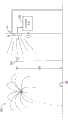
9A-9C depict a manner in which an object may be tracked by the tracking system of FIG. 1 in three spatial dimensions in accordance with embodiments of the present disclosure;
FIG. 10 is a flow chart illustrating an embodiment of a method of tracking reflections using the tracking system of FIG. 1 and controlling an amusement park element based on the tracked reflections, according to an embodiment of the present disclosure;
FIG. 11 is a perspective view of the tracking system of FIG. 1 used in an investigation apparatus to determine changes in elevation or coloration of a structure, in accordance with an embodiment of the present disclosure;
FIG. 12 is a schematic representation of the manner in which the tracking system of FIG. 1 monitors changes in the topography of a structure having retroreflective markers located beneath the surface in accordance with an embodiment of the present disclosure;
FIG. 13 is a perspective view of the tracking system of FIG. 1 used to survey an amusement park ride including a support structure and a track to determine changes in the structural elevation of the ride, in accordance with an embodiment of the present disclosure;
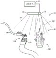
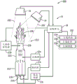
FIG. 14 is a perspective view of the tracking system of FIG. 1 used to monitor amusement park ride vehicles and flame effects in accordance with an embodiment of the present disclosure;
FIG. 15 is a cross-sectional side view of a flame generating device monitored and controlled by the tracking system of FIG. 1, according to an embodiment of the disclosure;
FIG. 16 is a perspective view of the tracking system of FIG. 1 being used to monitor the height of an ordinance (cordinance) in a fireworks show, in accordance with an embodiment of the present disclosure;
FIG. 17 is a cross-sectional side view of a ordinance having an electronic detonator attached to its housing and retro-reflective markers to enable the ordinance to be tracked by the tracking system of FIG. 1 in accordance with an embodiment of the present disclosure; and
fig. 18 is a perspective view of a fireworks show using a robot actuated cannon controlled by the tracking system of fig. 1 in accordance with an embodiment of the present disclosure.
Detailed Description
Generally, a tracking system may track certain objects using various inputs obtained from the surrounding environment. The source of the input may depend, for example, on the type of tracking performed and the capabilities of the tracking system. For example, the tracking system may use sensors disposed in the environment to actively generate outputs that are received by the master controller. The controller may then process the generated output to determine certain information that is used for tracking. One example of such tracking may include tracking motion of an object to which the sensor is fixed. Such systems may also utilize one or more devices used to bathe an area with electromagnetic radiation, magnetic fields, or the like, wherein the electromagnetic radiation or magnetic field is used as a reference against which the output of the sensor is compared by the controller. As can be appreciated, such active systems can be quite expensive to employ if implemented to track many objects or even people, and are processor-intensive for the main controller of the tracking system.
Other tracking systems, such as certain passive tracking systems, may perform tracking without providing an illumination source, or the like. For example, some tracking systems may use one or more cameras to obtain a contour or rough skeletal estimate of an object, person, or the like. However, in situations where background lighting may be intense, such as outdoors on hot and sunny days, the accuracy of such systems may be reduced due to varying degrees of noise received by the detectors of passive tracking systems.
In view of the foregoing, it is now recognized that conventional tracking systems have certain drawbacks, and that improved tracking systems are desired for use in a variety of contexts, including amusement park attractions, work site monitoring, sports and security systems, and others. For example, it is currently recognized that improved tracking systems may be utilized to enhance operations in various amusement park environments and other entertainment attractions.
According to one aspect of the present disclosure, a dynamic signal-to-noise ratio tracking system uses emitted electromagnetic radiation and (in certain embodiments) retroreflection to enable detection of markers and/or objects within a field of view of the tracking system. The disclosed tracking system may include: an emitter configured to emit electromagnetic radiation in a field of view; a sensing device configured to detect electromagnetic radiation retro-reflected from an object within a field of view; and a controller configured to perform various processing and analysis routines including interpreting signals from the sensing devices and controlling the automated equipment based on the detected position of the object or marker. The disclosed tracking system may also be configured to simultaneously track multiple different objects (using the same emission and detection characteristics). In some embodiments, the tracking system tracks the position of retro-reflective markers placed on the object to estimate the position of the object. As used herein, a retroreflective marker is a reflective marker that is designed to retroreflect electromagnetic radiation back approximately in the direction from which the electromagnetic radiation is emitted. More specifically, retroreflective markers used in accordance with the present disclosure reflect electromagnetic radiation back toward the emission source within a narrow cone when illuminated. Conversely, certain other reflective materials (such as luminescent materials) may undergo diffuse reflection, wherein electromagnetic radiation is reflected in many directions. Still further, mirrors that also reflect electromagnetic radiation typically do not experience retroreflection. Conversely, the mirror undergoes specular reflection, wherein the angles of electromagnetic radiation (e.g., light such as infrared, ultraviolet, visible, or radio waves) incident on the mirror are reflected (away from the emission source) at equal but opposite angles.
Retroreflective materials used in accordance with the embodiments set forth below can be readily obtained from a number of commercial sources. One example includes retroreflective tape that can be adapted to many different objects (e.g., environmental features, articles of clothing, toys). Due to the manner in which retro-reflection occurs using such markers in combination with the detectors 16 used in accordance with the present disclosure, the retro-reflective markers cannot be eroded away by sunlight or even in the presence of other emitters that emit electromagnetic radiation at wavelengths that overlap the wavelengths of interest. Thus, the disclosed tracking system may be more reliable than existing optical tracking systems, especially in outdoor environments and in the presence of other electromagnetic emission sources.
While this disclosure is applicable to many different contexts, the presently disclosed embodiments are directed, among other things, to various aspects related to tracking changes to certain structures (e.g., buildings, support columns) within an amusement park and, in some cases, controlling amusement park equipment (e.g., automation equipment) based on information obtained from such dynamic signal-to-noise ratio tracking systems. Indeed, it is currently recognized that by using the disclosed tracking system, reliable and efficient amusement park operations may be performed that may otherwise create high levels of noise for other tracking systems, even though there are many moving objects, guests, employees, sounds, lights, etc. in an amusement park, particularly other optical tracking systems that do not use retro-reflective markers in the manner disclosed herein.
In certain aspects of the present disclosure, a control system of an amusement park (e.g., a control system associated with a particular area of the amusement park, such as a ride) may use information obtained by a dynamic signal-to-noise ratio tracking system to monitor and evaluate information about people, machines, vehicles (e.g., guest vehicles, service vehicles), and similar features in the area to provide information that facilitates more efficient operation of amusement park operations. For example, this information may be used to determine whether certain automated processes may be triggered or otherwise allowed to proceed. The information evaluated about vehicles in the amusement park may include, for example, location, movement, dimensions, or other information about automated machines, ride vehicles, etc. within certain areas of the amusement park. By way of non-limiting example, the information may be evaluated to track humans and machines in order to provide enhanced interactivity between humans and machines, to track and control unmanned aerial vehicles, to track and control ride vehicles, and any show effects associated with ride vehicles, and the like.
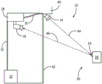
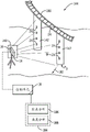
Certain aspects of the present disclosure may be better understood with reference to fig. 1, which generally illustrates the manner in which a dynamic signal-to-noise ratio tracking system 10 (hereinafter "tracking system 10") may be integrated with an amusement park device 12 according to the present embodiments. As illustrated, the tracking system 10 includes an emitter 14 (which may be all or part of an emission subsystem having one or more emitting devices and associated control circuitry) configured to emit one or more wavelengths of electromagnetic radiation (e.g., light, such as infrared light, ultraviolet light, visible light, or radio waves, etc.) in a general direction. The tracking system 10 also includes a detector 16 (which may be all or part of a detection subsystem having one or more sensors, cameras, etc. and associated control circuitry) configured to detect electromagnetic radiation reflected as a result of the emission, as described in more detail below.
To control the operation of the emitter 14 and detector 16 (the emission subsystem and the detection subsystem) and to perform various signal processing routines resulting from the emission, reflection, and detection processes, the tracking system 10 further includes a control unit 18 communicatively coupled to the emitter 14 and detector 16. Accordingly, the control unit 18 may include one or more processors 20 and one or more memories 22, which may be generally referred to herein as "processing circuitry". By way of specific but non-limiting example, the one or more processors 20 may include one or more Application Specific Integrated Circuits (ASICs), one or more Field Programmable Gate Arrays (FPGAs), one or more general purpose processors, or any combinations thereof. Additionally, the one or more memories 22 may include volatile memory (such as Random Access Memory (RAM)) and/or non-volatile memory (such as Read Only Memory (ROM)), an optical drive, a hard disk drive, or a solid state drive. In certain embodiments, control unit 18 may form at least a portion of a control system configured to coordinate the operation of various amusement park features, including devices 12. As described below, such an integrated system may be referred to as an amusement park attraction and control system.
The tracking system 10 is specifically configured to detect the position of illuminated components, such as retroreflective markers 24 having appropriately related retroreflective material relative to a grid, pattern, emission source, fixed or moving environmental element, or the like. In certain embodiments, the tracking system 10 is designed to utilize the relative positioning to identify whether there is a correlation between one or more such illuminated components and a particular action to be performed by the amusement park equipment 12 (such as triggering a show effect, dispatching a ride vehicle, closing a door, synchronizing a security camera with movement, etc.). More generally, actions may include control of machine movement, image formation or adaptation, and similar processes.
As illustrated, the retro-reflective markers 24 may be located on an object 26, which object 26 may correspond to any number of static or dynamic features. For example, object 26 may represent a boundary feature of an amusement park attraction, such as a floor, wall, door, etc., or may represent an item that may be worn by a guest, amusement park employee, or similar object. Indeed, as set forth below, within an amusement park attraction area, there may be many such retro-reflective markers 24, and the tracking system 10 may detect reflections from some or all of the markers 24, and may perform various analyses based on this detection.
Referring now to the operation of tracking system 10, emitter 14 operates to emit electromagnetic radiation (which for illustrative purposes is represented by expanded beam of electromagnetic radiation 28, beam of electromagnetic radiation 28) to selectively illuminate, bathe, or flood detection region 30 with electromagnetic radiation. Electromagnetic radiation beam 28 is intended to generally represent any form of electromagnetic radiation that may be used in accordance with the present embodiments, such as forms of light (e.g., infrared, visible, UV) and/or other bands of the electromagnetic spectrum (e.g., radio waves, etc.). However, it is also currently recognized that in certain embodiments it may be desirable to use certain bands of the electromagnetic spectrum depending on various factors. For example, in one embodiment, it may be desirable to use forms of electromagnetic radiation that are not visible to the human eye or within the audible range of human hearing so that the electromagnetic radiation used for tracking does not distract the guest from their experience. Further, it is also currently recognized that certain forms of electromagnetic radiation, such as certain wavelengths of light (e.g., infrared light), may be more desirable than others, depending on the particular environment (e.g., whether the environment is "dark" or whether one is expected to pass the path of the beam). Again, the detection area 30 may correspond to all or a portion of an amusement park attraction area, such as a stage show, a ride vehicle loading area, a waiting area outside of an entrance to a ride or show, or the like.
The beam of electromagnetic radiation 28 may in some embodiments represent a plurality of beams of light (beams of electromagnetic radiation) emitted from different sources (all parts of the emission subsystem). Further, in certain embodiments, the emitter 14 is configured to emit the beam of electromagnetic radiation 28 at a frequency that has a corresponding relationship with the material of the retroreflective marker 24 (e.g., is capable of being reflected by the retroreflective elements of the marker 24). For example, the retro-reflective markers 24 may include a coating of retro-reflective material disposed on the body of the object 26 or a piece of solid material coupled with the body of the object 26. By way of a more specific but non-limiting example, retroreflective materials can include spherical and/or prismatic reflective elements that are incorporated into the reflective material to enable retroreflection to occur. Again, in certain embodiments, there may be many such retro-reflective markers 24, and may be arranged in a particular pattern stored in the memory 22 to enable further processing, analysis, and control routines to be performed by the control unit 18 (e.g., a control system).
In particular, in operation, the detector 16 of the system 10 may be used to detect the beam 28 of electromagnetic radiation that is retro-reflected from the retro-reflective markers 24 and provide data associated with the detection to the control unit 18 via the communication line 31 for processing. The detector 16 is operable to specifically identify the mark 24 based on certain specific wavelengths of emitted and reflected electromagnetic radiation and thus avoid the problem of false detection. For example, the detector 16 may be specifically configured to detect certain wavelengths of electromagnetic radiation (e.g., corresponding to wavelengths emitted by the emitter 14) by using physical electromagnetic radiation filters, signal filters, and the like. Furthermore, the detector 16 may utilize a particular arrangement of optical detection features and electromagnetic radiation filters to capture substantially only the retro-reflected electromagnetic radiation.
For example, the detector 16 may be configured to detect wavelengths of electromagnetic radiation that are retroreflected by the retroreflective markers 24 while filtering wavelengths of electromagnetic radiation that are not retroreflected by the markers 24 (including those wavelengths of interest). Thus, the detector 16 may be configured to specifically detect (e.g., capture) the retro-reflected electromagnetic radiation while not detecting (e.g., capturing) electromagnetic radiation that is not retro-reflected. In one embodiment, the detector 16 may utilize directionality associated with retro-reflection to perform this selective filtering. Thus, while detector 16 receives electromagnetic radiation from various sources (including spurious reflected electromagnetic radiation as well as ambient electromagnetic radiation), detector 16 is specifically configured to filter out all or substantially all spurious reflected signals while retaining all or substantially all desired signals. Thus, in practice the signal-to-noise ratio of the signals processed by the detector 16 and the control unit 18 is very high, regardless of the signal-to-noise ratio present for the electromagnetic band of interest outside the detector 16.
For example, detector 16 may receive retro-reflected electromagnetic radiation (e.g., from retro-reflective markers 24) and ambient electromagnetic radiation from within an area (e.g., a guest attraction area). Ambient electromagnetic radiation may be filtered, while retro-reflected electromagnetic radiation (which is directional) may not be filtered (e.g., the filter may be bypassed). Thus, in certain embodiments, the "image" generated by the detector 16 may include a substantially dark (e.g., black or blanked) background signal, wherein substantially only the retro-reflected electromagnetic radiation produces contrast.
According to some embodiments, the retro-reflected electromagnetic radiation may comprise different wavelengths that are distinguishable from each other. In one embodiment, the filter of the detector 16 may have optical properties and may be located within the detector such that the optical detection device of the detector 16 receives substantially only the electromagnetic wavelengths that are retroreflected by the retroreflective markers 24 (or other retroreflective elements) as well as any desired background wavelengths (which may provide background or other landscape information). To generate a signal from the received electromagnetic radiation, detector 16 may be, by way of example, a camera having a plurality of electromagnetic radiation capturing features, such as Charge Coupled Devices (CCDs) and/or Complementary Metal Oxide Semiconductor (CMOS) sensors corresponding to pixels. In one example embodiment, the detectors 16 may be amp High Dynamic Range (HDR) camera systems available from Contrast Optical Design and Engineering, Inc. of Albuquerque, N.Mexico.
Since the retro-reflection effected by the retro-reflective markers 24 causes a cone of reflected electromagnetic radiation to be incident on the detector 16, the control unit 18 may in turn relate the center of the cone, where the reflected electromagnetic radiation is most intense, to the point source of reflection. Based on this correlation, the control unit 18 may identify and track the location of this point source, or may identify and monitor the pattern of reflections achieved by many such retroreflective markers 24.
For example, once the control unit 18 receives the data from the detector 16, the control unit 18 may employ the known visible boundary or established orientation of the detector 16 to identify a location (e.g., coordinates) corresponding to the detected retroreflective markers 24. When there are multiple fixed retroreflective markers 24, the control unit 18 may store known locations (e.g., positions) of the retroreflective markers 24 to enable reflective pattern monitoring. By monitoring the reflection pattern, control unit 18 may identify that certain retroreflective markers 24 are obstructed (blocked) by various moving objects, guests, employees, etc. It should also be noted that the basis for these comparisons may be updated based on, for example, how long a particular retroreflective marker 24 has been located and used in its position. For example, the stored reflection pattern associated with one of the markers 24 may be periodically updated during a calibration phase that includes a period of time during which it is expected that no object or person will pass the marker 24. Such recalibration may be performed periodically such that markers that have been employed for extended periods of time and have lost their retroreflective ability are not mistaken for detected blocking events.
In other embodiments, the tracking system 10 may be configured to detect and track various other objects located within the detection region 30 in addition to or in lieu of tracking one or more of the retro-reflective markers 24. Such objects 32 may include, among other things, ride vehicles, people (e.g., guests, employees), and other moving amusement park equipment. For example, the detector 16 of the system 10 may be used to detect the beam 28 of electromagnetic radiation that bounces back from the object 32 (without the retro-reflective markers 24) and provide data associated with this detection to the control unit 18. That is, the detector 16 may detect the object 32 based entirely on diffuse or specular reflection of electromagnetic energy from the object 32. In certain embodiments, the object 32 may be coated with a specific coating that reflects the beam of electromagnetic radiation 28 in a detectable and predetermined manner. Thus, once control unit 18 receives the data from detector 16, control unit 18 may determine that the coating associated with object 32 reflected the electromagnetic radiation, and may also determine the source of the reflection to identify the location of object 32.
Whether the retro-reflective markers 24 are fixed or moving, the process of emitting the beam of electromagnetic radiation 28, sensing reflected electromagnetic radiation from the retro-reflective markers 24 (or the object 32 without or essentially without retro-reflective material), and determining the position of the retro-reflective markers 24 or the object 32 may be performed multiple times within a short period of time by the control unit 18. This process may be performed at different intervals, wherein the process is initiated at a predetermined point in time, or may be performed substantially continuously such that it is re-initiated substantially immediately after the process is completed. In embodiments where the retroreflective marker 24 is fixed and the control unit 18 performs retroreflective pattern monitoring to identify marker obstructions, the process may be performed at intervals to obtain a single retroreflective pattern at each interval. This may be considered to represent a single frame having a reflection pattern corresponding to the pattern of blocked and unblocked retroreflective markers 24.
On the other hand, such programs may be executed essentially continuously to facilitate identifying the path and/or trajectory through which the retroreflective markers 24 have moved. The marker 24 moving within the detection zone 30 will be detected within a particular time frame or simply in a continuous series. Here, a pattern of reflections will be generated and recognized over a period of time.
According to the embodiments set forth above, the detector 16 and control unit 18 may operate over a variety of different time frames depending on the tracking to be performed and the expected movement of the tracked object through space and time. By way of example, the detector 16 and control unit 18 may operate in conjunction to complete all logic processes (e.g., update analysis and control signals, process signals) in the time interval between capture events of the detector 16. Such processing speeds may enable substantially real-time tracking, monitoring, and control, where applicable. By way of non-limiting example, the detector capture event may be between about 1/60 seconds and about 1/30 seconds, thus generating between 30 and 60 frames per second. The detector 16 and control unit 18 may operate to receive, update, and process signals between the capture of each frame. However, any interval between capture events may be utilized according to some embodiments.
Once a particular pattern of retro-reflections has been detected, a determination may be made by the control unit 18 as to whether the pattern relates to a stored pattern that is recognized by the control unit 18 and that corresponds to a particular action to be performed by the amusement park device 12. For example, the control unit 18 may perform a comparison of the position, path, or trajectory of the retro-reflective markers 24 with stored positions, paths, or trajectories to determine an appropriate control action for the device 12. Additionally or alternatively, as described in more detail below, the control unit 18 may determine whether a particular pattern obtained at a particular point in time is related to a stored pattern associated with a particular action to be performed by the amusement park device 12. Still further, the control unit 18 may determine whether a particular set of patterns obtained at a particular point in time is related to a stored pattern change associated with a particular action to be performed by the amusement park equipment 12.
While control unit 18 may cause certain actions to be automatically performed within the amusement park in the manner set forth above, it should be noted that analyses similar to those mentioned above may also be applied to prevent certain actions (e.g., blocking actions or being blocked from performing actions at amusement park equipment 12). For example, in situations where the ride vehicle may be automatically dispatched, the control unit 18 may stop the automatic dispatch based on tracking changes in the retro-reflective markers 24, or the dispatch may even be prevented by the ride operator before additional measures are taken (e.g., additional confirmation that the ride vehicle is picked up for departure). Such control may also be applied to other amusement park equipment. For example, flame effects, fireworks or similar show effects may be prevented from being triggered, may be stopped or may be reduced in intensity due to intervention by the control unit 18 as a result of certain pattern determinations as described herein.
Having generally described the configuration of the system 10, it should be noted that the arrangement of the emitters 14, detectors 16, control unit 18, and other features may vary based on application specific considerations and the manner in which the control unit 18 performs the evaluation based on the electromagnetic radiation from the retroreflective markers 24. In the embodiment of the tracking system 10 shown in fig. 1, the emitter 14 and the sensor or detector 16 are integral features such that the plane of operation associated with the detector 16 substantially overlaps the plane of operation associated with the emitter 14. That is, the detector 16 is located at substantially the same position as the emitter 14, which may be desirable due to the retroreflectivity of the markers 24. However, the present disclosure is not necessarily limited to this configuration. For example, as described above, retroreflection can be associated with a reflective cone, with the highest intensity in the middle of the reflective cone. Thus, the detector 16 may be located within an area in which the reflective cone of the retro-reflective marker is not as strong as its center, but still can be detected by the detector 16.
By way of non-limiting example, in certain embodiments, the emitter 14 and the detector 16 may be coaxial. However, the detector 16 (e.g., an infrared camera) may be located at a different location relative to the emitter 14, and the emitter 14 may include an infrared light bulb, one or more diode emitters, or similar source. As illustrated in FIG. 2, the emitter 14 and detector 16 are separate and located at different locations on an environmental feature 40 (e.g., a wall or ceiling) of the entertainment attraction area. Specifically, the emitter 14 of FIG. 2 is located outside of a window 42 of the storefront containing the other components of the system 10. The detector 16 of fig. 2 is located remotely from the emitter 14, but is still oriented to detect electromagnetic radiation reflected from the retro-reflective markers 24 and originating from the emitter 14.
For illustrative purposes, arrows 44, 46 indicate that a beam of light (a beam of electromagnetic radiation) is emitted from the emitter 14 (arrow 44) into the detection area 30, retroreflected (arrow 46) by the retroreflective markers 24 on the object 26, and detected by the detector 16. The beam represented by arrow 44 is only one of many electromagnetic radiation emissions (beams) that flood or otherwise selectively illuminate the detection region 30 from the emitter 14. It should be noted that other embodiments may utilize different arrangements and implementations of the components of system 10 in different environments in accordance with the present disclosure.
Having now discussed the general operation of the tracking system 10 to detect the position of the retro-reflective markers 24 and/or objects 32, as shown in FIG. 1, certain applications of the tracking system 10 will be described in more detail below. For example, it may be desirable to track the location of people within a particular area by using the disclosed tracking system. This may be useful, for example, to control routing in a ride vehicle loading area, control access to different areas, determine appropriate times at which show effects may be triggered, determine appropriate times at which certain automated machines may be moved, and may also be useful to assist in real-time show performances (e.g., blocking actors on a stage). That is, during a performance, it is assumed that an actor will be standing at a particular location on the stage at some time. To ensure that the actors reach their proper positions at the correct times, the tracking system 10 may be mounted on the stage and used to track the position and/or movement of all actors on the stage. Feedback from the tracking system 10 may be used to assess how well the actor has reached a desired point on the stage.
In addition to on-stage deterrence, the tracking system 10 may be used in contexts involving tracking and/or evaluating shoppers in stores or other commercial environments. That is, the store may be equipped with the disclosed tracking system 10 to determine where guests spend time within the store. Instead of triggering a show effect, such a tracking system 10 may be used to monitor the flow of people within the store and thus control the availability of certain items, control the flow of people's movements, and the like. For example, information gathered via the disclosed tracking system 10 may be used to identify and evaluate which equipment or displays within a store are most attractive, to determine what items are most popular for sale or to determine which areas of the store (if any) are too crowded. This information can be analyzed and used to improve store layout, product development, and congestion management, among other things.
It should be noted that there may be other applications for tracking the location of people, objects, machines, etc. within an area than those described above. The presently disclosed tracking system 10 may be configured to identify and/or track the location and movement of people and/or objects within the detection area 30. The tracking system 10 may accomplish this tracking in a number of different ways that are described above and explained in more detail below. It should be noted that tracking system 10 is configured to simultaneously detect the location of one or more persons, one or more objects 32, or a combination of different features in the same detection area 30 using a single emitter 14, detector 16, and control unit 18. However, the use of a plurality of such emitters 14, detectors 16, and control units 18 is also within the scope of the present disclosure. Thus, one or more of the emitters 14 and one or more of the detectors 16 may be present in the detection region 30. Considerations such as the type of tracking to be performed, the desired tracking range, redundancy for the tracking, etc. may determine, at least in part, whether to utilize multiple or single emitters and/or detectors.
For example, as described above, the tracking system 10 may generally be configured to track target movement spatially and temporally (e.g., over time within the detection region 30). When utilizing a single detection device (e.g., detector 16), the tracking system 10 may monitor the retro-reflected electromagnetic radiation from a defined orientation to track a person, object, etc. Since detector 16 has only one view angle, such detection and tracking may be limited in certain embodiments to performing tracking in only one plane of movement (e.g., tracking is in two spatial dimensions). As an example, such tracking may be utilized in situations where the tracked object has a relatively low number of degrees of freedom, such as when movement is limited to a constrained path (e.g., a track). In one such embodiment, the target has a determined vector orientation.
On the other hand, when multiple detection devices (e.g., two or more of the detectors 16) are utilized to track an object both in space and time, the tracking system 10 may monitor the retro-reflected electromagnetic radiation from multiple orientations. Using these multiple vantages, the tracking system 10 may be capable of tracking targets having multiple degrees of freedom. In other words, the use of multiple detectors may provide both vector orientation and range for the tracked object. Such tracking may be particularly useful in situations where it may be desirable to allow the tracked object to have unrestricted movement in space and time.
Multiple detectors may also be desirable for redundancy in tracking. For example, a plurality of detection devices applied to a situation in which the movement of the target is limited or not limited may enhance the reliability of the tracking performed by the tracking system 10. The use of redundant detectors 16 may also enhance tracking accuracy and may help prevent geometric blockage of the target by complex geometric surfaces (such as tortuous paths, hills, folded clothing, open doors, etc.).
According to one aspect of the present disclosure, the tracking system 10 may track the relative positions of multiple targets (e.g., people, objects, machines) located within the detection area 30 by using the retro-reflective markers 24. As illustrated in fig. 3, retroreflective markers 24 may be disposed on person 70. Additionally or alternatively, the marker 24 may be located on a machine or other object (e.g., object 26). Thus, the techniques disclosed herein for tracking the movement of person 70 in space and time may also be applied to the movement of objects in an amusement park in addition to or as an alternative to person 70. In such embodiments, the marker 24 may be located on or outside of the object 26 (e.g., a home), as shown in fig. 1.
In the embodiment illustrated in fig. 3, retroreflective markers 24 are disposed on the outside of a person's clothing. For example, the retroreflective marker 24 may be applied as a strip of retroreflective tape that is applied to an armband, a headband, a shirt, a personal identification feature, or other item. Additionally or alternatively, the retroreflective markers 24 may be sewn into a garment or applied as a coating to a garment in some embodiments. Retroreflective markers 24 may be disposed on the clothing of person 70 at locations that are accessible to the beam of electromagnetic radiation 28 emitted from emitter 14. As the person 70 walks around the detection area 30 (in the case of an object 32, the object 32 may move through the area 30), the beam of electromagnetic radiation 28 reflects off of the retro-reflective markers 24 and back to the detector 16. The detector 16 communicates with the control unit 18 by sending a signal 72 to the processor 20, this signal 72 being indicative of the reflected electromagnetic radiation detected via the detector 16. The tracking system 10 may interpret this signal 72 to track the location or path of the person 70 (or object 32) moving about the specified area (i.e., track the person or object in space and time). Again, depending on the number of detectors 16 utilized, the control unit 18 may determine the vector magnitude, orientation, and meaning of the movement of the person and/or object based on the received retro-reflected electromagnetic radiation.
The tracking of a person 70 (which may also represent a moving object) is schematically illustrated in fig. 4. More specifically, fig. 4 illustrates a series 80 of frames 82 captured by the detector 16 (e.g., camera) over a period of time. As described above, multiple such frames (e.g., between 30 and 60) may be generated per second in some embodiments. It should be noted that fig. 4 may not be an actual representation of the output produced by the tracking system 10, but is described herein to facilitate an understanding of the tracking and monitoring performed by the control unit 18. The frames 82 each represent the detection area 30 and the position of the retroreflective markers 24 within the area 30. Alternatively, frame 82 may instead represent a marker blockage within region 30, such as where the grid of markers 24 is blocked by an object or person.
As shown, the first frame 82A includes a first instance of a retro-reflective marker (designated as 24A) having a first position. As the series 80 progresses over time, the second frame 82B includes a second instance of the retro-reflective markers 24B, which is shifted relative to the first instance, and so on (thereby producing third and fourth instances of the retro- reflective markers 24C and 24D). After a certain period of time, the control unit 18 has generated the series 80, wherein the operation of generating the series 80 is generally indicated by arrow 84.
The series 80 may be evaluated by the control unit 18 in many different ways. According to the illustrated embodiment, control unit 18 may assess the movement of person 70 or object 32 by assessing the position of markers 24 (or the obstruction of certain markers) over time. For example, the control unit 18 may obtain the vector orientation, range, and meaning of the movement with respect to the tracked object according to the number of detectors 16 utilized to perform tracking. In this way, it can be said that the control unit 18 will evaluate the composite frame 86 representing the movement of the tracked retroreflective markers 24 (or the tracked obstructions of the markers 24) over time within the detection area 30. Thus, the composite frame 86 includes various instances of the retro-reflective markers 24 (including 24A, 24B, 24C, 24D), which may be analyzed to determine the overall movement of the markers 24 (and thus the person 70 and/or the object 26, whichever may be the case).
As also illustrated in fig. 4, this monitoring may be performed with respect to certain environmental elements 88 (which may be fixed within the detection region 30 and/or may be associated with a reflective material). The control unit 18 may perform operations based not only on the detected position of the marker 24, but also on extrapolated movement about the environmental element 88 (e.g., the projected path of the retroreflective marker 24 through the detection area 30 or the projected position blocked by the marker grid).
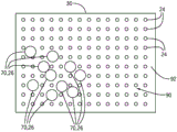
Another method for tracking one or more persons 70 or objects 32 in an area is schematically illustrated in fig. 5. In particular, FIG. 5 shows a top view of a group of people 70 standing in the detection area 30. Although not shown, the tracking system 10 may be present directly above this detection area 30 in order to detect the location of the person 70 (and other objects) present within the detection area 30 (e.g., to obtain a plan view of the detection area 30). In the illustrated embodiment, the retroreflective markers 24 are located in a grid pattern 90 on a floor 92 of the detection area 30 (e.g., as a coating, tape, or similar attachment method). The retroreflective markers 24 (e.g., grids, diamonds, lines, circles, solid coatings, etc.) may be arranged in any desired pattern, which may be a regular pattern (e.g., a repeating) or a random pattern.
This grid pattern 90 may be stored in memory 22, and portions of grid pattern 90 (e.g., individual markers 24) may be associated with the locations of certain environmental elements and amusement park features (e.g., amusement park devices 12). In this way, the position of each marker 24 relative to such elements can be known. Thus, when the markers 24 retroreflect the beam 28 of electromagnetic radiation to the detector 16, the position of the reflecting markers 24 may be determined and/or monitored by the control unit 18.
As illustrated, when a person 70 or object 32 is positioned on one or more of the retro-reflective markers 24 on the floor 92, the blocked markers cannot reflect the emitted electromagnetic radiation back to the detector 16 above the floor 92. Indeed, according to embodiments, the grid pattern 90 may include retroreflective markers 24 that are spaced apart by a distance that allows a person or object (e.g., at least one of the blocking retroreflective markers 24) located on the floor 92 to be detectable. In other words, the distance between the markers 24 may be small enough so that an object or person may be located on at least one of the retroreflective markers 24.
In operation, the detector 16 may be used to detect the beam 28 of electromagnetic radiation that is retroreflected from the retroreflective markers 24 that are not obscured by a person or object located in the detection area 30. As discussed above, the detector 16 may then provide data associated with this detection to the control unit 18 for processing. The control unit 18 may perform a comparison of the detected beam of electromagnetic radiation (e.g., the detected pattern) reflected back from the uncovered retroreflective markers 24 to the stored locations of the completely uncovered grid pattern 90 (e.g., the stored pattern) and/or other known grid patterns caused by obstruction of certain markers 24. Based on this comparison, control unit 18 may determine which markers 24 are covered to then approximate the position of person 70 or object 32 within the plane of floor 92. Indeed, using a grid located on the floor 92 in conjunction with a single detector 16 may enable tracking movement in two dimensions. If higher order tracking is desired, additional grids and/or additional detectors 16 may be utilized. In certain embodiments, based on the location of person 70 or object 32 in detection area 30, control unit 18 may adjust the operation of amusement park equipment 12.
The process of emitting the beam of electromagnetic radiation 28, sensing reflected electromagnetic radiation from the uncovered retroreflective markers 24 on the floor 92, and determining the position of the person 70 may be performed by the control unit 18 multiple times within a short period of time in order to identify a series of positions of the person 70 (to track the movement of the group) moving near the floor 92. Indeed, such procedures may be performed essentially continuously to facilitate identifying the path through which the person 70 has moved within the detection region 30 during a particular time frame or simply in a continuous series. Once the location or path of one or more of persons 70 has been detected, control unit 18 may further analyze the location or path to determine whether any actions should be performed by device 12.
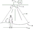
As discussed in detail above with respect to fig. 1, the control unit 18 may be configured to identify certain objects within the detection area 30 that are expected to pass through the path of the beam of electromagnetic radiation 28, including objects that are not marked with retroreflective material. For example, as illustrated in fig. 6, certain embodiments of the tracking system 10 may be configured to enable the control unit 18 to identify a person 70 (which is also intended to represent the object 32) located in the detection area 30 without using the retro-reflective markers 24. That is, the control unit 18 may receive data indicative of electromagnetic radiation reflected back from the detection region 30, and the control unit 18 may compare the digital signature of the detected radiation to one or more possible data signatures stored in the memory 22. That is, if the signature of the electromagnetic radiation reflected back to the detector 16 matches the signature of the person 70 or known object 32 sufficiently closely, the control unit 18 may determine that the person 70 or object 32 is located in the detection region 30. For example, the control unit 18 may identify "dark spots" or areas within the detection area 30 where electromagnetic radiation is absorbed rather than reflected. These regions may have geometries that the control unit 18 may analyze (e.g., by comparing to stored shapes, sizes, or other characteristics of objects or persons) to identify the presence, location, size, shape, etc. of objects (e.g., person 70).
As may be appreciated with reference to fig. 1, 2, 3, and 6, the tracking system 10 may be located in various locations to obtain different views of the detection region 30. Indeed, it is now recognized that different locations and combinations of locations of one or more of the various tracking systems 10 (or one or more elements of the tracking systems 10, such as the plurality of detectors 16) may be desired in order to obtain certain types of information about the retroreflective markers 24 and their obstructions. For example, in fig. 1, the tracking system 10, and in particular the detector 16, is positioned to obtain an elevation view of at least the object 26 and the object 32 equipped with the retro-reflective markers 24. In fig. 2, the detector 16 is positioned to obtain a top perspective view of the detection region 30 that enables detection of the retro-reflective markers 24 located on various environmental elements, moving objects, or persons. In the embodiment of fig. 3 and 6, the detector 16 may be positioned to obtain a plan view of the detection region 30.
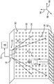
These different views may provide information of control actions that may be used by the control unit 18 for particular types of analysis and, in some embodiments, may depend on the particular environment in which they are located. For example, in fig. 7, the tracking system 10, and in particular the emitter 14 and detector 16, are positioned to obtain a perspective view of the person 70 (or object 32) in the detection region 30. The detection area 30 includes a floor 92 and also includes walls 93 on which the retroreflective markers 24 are located to form the grid pattern 90. Here, the person 70 is blocking a subset of the markings 24 located on the wall 93. A subset of the markers 24 cannot be illuminated by the emitter 14, cannot retroreflect electromagnetic radiation back to the detector 16, or both, because the person 70 (also intended to represent an object) is located between the subset of markers 24 and the emitter 14 and/or detector 16.
The grid pattern 90 on the wall 93 may provide information not necessarily available from the plan views as shown in fig. 3 and 6. For example, the obstruction of the retroreflective markers 24 enables the control unit 18 to determine the height of the person 70, the outline of the person 70 or the size of the object 32 in embodiments in which the object 32 is present, the outline of the object 32, and the like. Such a determination may be made by the control unit 18 to assess whether the person 70 meets height requirements for the ride, assess whether the person 70 is associated with one or more objects 32 (e.g., bags, walkers), and may also be used to track movement of the person 70 or object 32 through the detection area 30 with greater accuracy than the plan views set forth in fig. 3 and 6. That is, the control unit 18 is better able to associate the movement identified by the obstruction of the indicia 24 with the particular person 70 by determining the person's profile, height, etc. Likewise, the control unit 18 is better able to track the movement of the object 32 through the detection region 30 by identifying the geometry of the object 32 and in particular linking the identified movement with the object 32. In certain embodiments, tracking the height or contour of the person 70 may be performed by the tracking system 10 to enable the control unit 18 to provide recommendations to the person 70 based on an analysis of the person's estimated height, contour, and the like. Similar determinations and recommendations may be provided for an object 32, such as a vehicle. For example, the control unit 18 may analyze the profile of a guest at entry to a queuing area for a ride. The control unit 18 may compare the overall size, height, etc. of the person 70 to the ride rules in order to alert the individual or provide confirmation that he is able to ride the ride before spending time in line. Likewise, the control unit 18 may analyze the overall size, length, height, etc. of the vehicle to provide parking recommendations based on available space. Additionally or alternatively, the control unit 18 may analyze the overall size, profile, etc. of the automated equipment components before allowing the equipment to perform a particular task (e.g., move through a group of people).
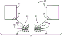
The pattern 90 may also be located on both the wall 93 and the floor 92. Thus, the tracking system 10 may be able to receive the retro-reflected electromagnetic radiation from the markers 24 on the wall 93 and floor 92, thereby enabling monitoring of movement in three dimensions and detection of marker blockage. In particular, the wall 93 may provide information in a height direction 94, while the floor 92 may provide information in a depth direction 96. The information from both the height direction 94 and the depth direction 96 may be correlated to each other using information from the width direction 98, which may be obtained from both a plan view and an elevation view.
Indeed, it is now recognized that if two objects 32 or persons 70 overlap in the width direction 98, they may be at least partially resolved from each other using information obtained from the depth direction 96. Furthermore, it is now also recognized that the use of multiple emitters 14 and detectors 16 at different locations (e.g., different locations in the width direction 98) may enable resolution of height and profile information when some information may be lost or when there is only one emitter 14 and detector 16 that is not readily resolved. More specifically, if there is an overlap between the object 32 or person 70 in the width direction 98 (or more generally, in the direction between the marker 24 on the wall 93 and the detector 16), using only one emitter 14 and detector 16 may result in the loss of some information. However, embodiments using multiple (e.g., at least two) detectors 16 and/or emitters 14 may cause a distinctive retro-reflective pattern to be generated by the markers 24 and viewed from detectors 16 and/or emitters 14 located at different viewing angles. Indeed, since the marker 24 is retroreflective, it will cause the electromagnetic radiation to retroreflect back towards the electromagnetic radiation source, even when multiple sources are emitted substantially simultaneously. Thus, electromagnetic radiation emitted from a first one of the emitters 14 from a first viewing angle will be reflected back by the marker 24 towards the first one of the emitters 14, while electromagnetic radiation emitted from a second one of the emitters 14 at a second viewing angle will be reflected back by the marker 24 towards the second one of the emitters 14, which enables multiple sets of tracking information to be generated and monitored by the control unit 18.
It is also now recognized that the retroreflective markers 24 on the wall 93 and floor 92 may be the same or different. Indeed, the tracking system 10 may be configured to use the directionality of the retro-reflected electromagnetic radiation from the walls 93 and the floor 92 to determine which electromagnetic radiation is reflected from the walls 93 relative to which electromagnetic radiation is reflected from the floor 92. In other embodiments, different materials may be used for indicia 24, such that, for example, different wavelengths of electromagnetic radiation may be reflected by the different materials back toward emitter 14 and detector 16. As an example, the retroreflective markers 24 on the floor 92 and the wall 93 can have the same retroreflective elements, but different layers for filtering or otherwise absorbing portions of the emitted electromagnetic radiation, such that the electromagnetic radiation reflected by the retroreflective markers 24 on the floor 92 and the wall 93 is of a characteristic and of different wavelengths. Since different wavelengths will be retroreflected, the detector 16 can detect these wavelengths and separate them from the ambient electromagnetic radiation filtered by the filtering elements within the detector 16.
To aid in illustration, fig. 8 depicts an enlarged cross-sectional view of an exemplary retroreflective marker 24 disposed on a floor 92 and wall 93 within the detection area 30. The markings 24 on the floor 92 and wall 93 each include a reflective layer 96 and a layer of retroreflective material 98, which may be the same or different for the floor 92 and wall 93. In the illustrated embodiment, they are identical. During operation, electromagnetic radiation emitted by emitter 14 may pass through transmissive coating 99 before striking retroreflective material layer 98. Thus, the transmissive coating 99 may be used to tune the wavelength of the electromagnetic radiation that is retroreflected by the marked indicia. In fig. 8, the indicia 24 on the floor 92 includes a first transmissive coating 99A that is different from a second transmissive coating 99B in the indicia 24 on the wall 93. In certain embodiments, the different optical properties between the first and second transmissive coatings 99A, 99B may cause different bandwidths of electromagnetic radiation to be reflected by the markings 24 on the floor 92 and the markings 24 on the wall 93. Although presented in the context of being disposed on a floor 92 and walls 93, it should be noted that markers 24 having different optical properties may be used on various different elements within the amusement park (such as on people and environmental elements, people and mobile devices, etc.) to facilitate separation for processing and monitoring by control unit 18.
Any one or combination of the techniques set forth above may be used to monitor a single object or person or multiple objects or persons. Indeed, even when only one detector 16 is utilized, it is currently recognized that three-dimensional tracking may be enabled with a combination of multiple retroreflective marker grids (e.g., on the floor 92 and wall 93 as set forth above) or a combination of one or more retroreflective marker grids affixed to a moving object or person and one or more tracked retroreflective markers 24. Further, it is also recognized that using multiple retro-reflective markers 24 on the same person or object may enable the tracking system 10 to track both position and orientation.
In this regard, fig. 9A illustrates an embodiment of an object 26 having a plurality of retroreflective markers 24 located on different faces of the object 26. Specifically, in the illustrated embodiment, the retro-reflective markers 24 are disposed on three different points of the object 26 that correspond to three orthogonal directions (e.g., X, Y and the Z-axis) of the object 26. However, it should be noted that other placements of the plurality of retroreflective markers 24 may be used in other embodiments. In addition, the tracking depicted in fig. 9A may be performed as generally illustrated, or a grid of retroreflective markers 24 as shown in fig. 7 may also be utilized.
As described above, the tracking system 10 may include, for example, a plurality of detectors 16 configured to sense electromagnetic radiation reflected back from the object 26. Each retro-reflective marker 24 disposed on the object 26 may retro-reflect the emitted electromagnetic radiation beam 28 at a particular, predetermined frequency of the electromagnetic spectrum of the electromagnetic radiation beam 28. That is, the retroreflective markers 24 may retroreflect the same or different portions of the electromagnetic spectrum, as generally set forth above with respect to fig. 8.
The control unit 18 is configured to detect and discriminate the electromagnetic radiation reflected at these particular frequencies, and thus track the motion of each of the individual retroreflective markers 24. In particular, the control unit 18 may analyze the detected positions of the individual retroreflective markers 24 to track the roll (e.g., rotation about the Y-axis), pitch (e.g., rotation about the X-axis), and yaw (e.g., rotation about the Z-axis) of the object 26. That is, instead of only determining the position of the object 26 in space relative to a particular coordinate system (e.g., defined by the detection region 30 or the detector 16), the control unit 18 may determine the orientation of the object 26 within the coordinate system, which enables the control unit 18 to perform enhanced tracking and analysis of the movement of the object 26 in space and time through the detection region 30. For example, the control unit 18 may perform predictive analysis to estimate a future location of the object 26 within the detection region 30, which may enable enhanced control of movement of the object 26 (e.g., to avoid collisions, take a particular path through an area).
In certain embodiments, such as when the object 26 is a motorized object, the tracking system 10 may track the position and orientation of the object 26 (e.g., a ride vehicle, a robot, an unmanned aerial vehicle) and control the object 26 to advance along the path in a predetermined manner. The control unit 18 may additionally or alternatively compare the results with the expected position and orientation of the object 26, for example to determine whether the object 26 should be controlled to adjust its operation and/or to determine whether the object 26 is operating properly or requires some maintenance. Additionally, the estimated position and orientation of the object 26 determined via the tracking system 10 may be used to trigger actions (including blocking certain actions) by other amusement park devices 12 (e.g., show effects). As one example, the object 26 may be a ride vehicle and the amusement park equipment 12 may be a show effect. In this example, it may be desirable to trigger only amusement park devices 12 when object 26 is in the desired position and/or orientation.
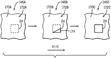
Continuing with the manner in which tracking in three spatial dimensions may be preformed, fig. 9B depicts an example of an object having a first marker 24A, a second marker 24B, and a third marker 24C located at similar positions as set forth in fig. 9A. However, from the perspective of a single one of the detectors 16, the detectors 16 can see a two-dimensional representation of the markers 24A, 24B, 24C and the object 16. From a first perspective (e.g., top or bottom view), the control unit 18 may determine that the first and second markers 24A, 24B are separated by a first viewing distance d1, the first and third markers 24A, 24C are separated by a second viewing distance d2, and the second and third markers 24B, 24C are separated by a third viewing distance d 3. The control unit 18 may compare these distances to known or calibrated values to estimate the orientation of the object 26 in three spatial dimensions.
Moving to fig. 9C, as the object 26 rotates, the detector 16 (and correspondingly the control unit 18) may detect that the apparent shape of the object 26 is different. However, the control unit 18 may also determine that the first and second marks 24A, 24B are separated by the adjusted first viewing distance d1', that the first and third marks 24A, 24C are separated by the adjusted second viewing distance d2', and that the second and third marks 24B, 24C are separated by the adjusted third viewing distance d3 '. The control unit 18 may determine the difference between the distance detected in the orientation in fig. 9B and the distance detected in the orientation in fig. 9C to determine how the orientation of the object 26 has been changed to then determine the orientation of the object 26. Additionally or alternatively, the control unit 18 may compare the adjusted observed distances d1', d2', d3' caused by the rotation of the object 26 with the stored values to estimate the orientation of the object 26 in three spatial dimensions, or to further refine the updating of the orientation determined based on the change between the distances in fig. 9B and 9C.
As set forth above, the present embodiment is directed to, among other things, tracking objects and/or people within an amusement park environment using the disclosed tracking system 10. As a result of this tracking, control unit 18 may, in some embodiments, cause certain automated functions to be performed within various subsystems of the amusement park. Having thus described the general operation of the disclosed tracking system 10, more specific embodiments of tracking and control operations are provided below to facilitate a better understanding of certain aspects of the present disclosure.
Turning now to FIG. 10, an embodiment of a method 100 of monitoring changes in reflected electromagnetic radiation to track movement of a target and control amusement park equipment according to the results of such monitoring is illustrated as a flow chart. In particular, method 100 includes the use of an emission subsystem to flood (block 102) one or more of the emitters 14 (e.g., emission subsystems) of the detection region 30 with electromagnetic radiation (e.g., electromagnetic radiation beam 28). For example, the control unit 18 may cause one or more of the emitters 14 to intermittently or substantially continuously flood the detection region 30 with emitted electromagnetic radiation. Again, the electromagnetic radiation may be any suitable wavelength capable of being retroreflected by the retroreflective markers 24. This includes, but is not limited to, ultraviolet, infrared, and visible wavelengths of the electromagnetic spectrum. It will be appreciated that different emitters 14, and in some embodiments different markers 24, may utilize different wavelengths of electromagnetic radiation to facilitate differentiation of the various elements within region 30.
After filling the detection area 30 with electromagnetic radiation in accordance with acts generally represented by block 102, the method 100 proceeds to detect (block 104) electromagnetic radiation that has been reflected from one or more elements (e.g., the retro-reflective markers 24) in the detection area 30. The detection may be performed by one or more of the detectors 16 that may be positioned relative to the emitter 14 as generally set forth above with respect to fig. 1 and 2. As described above and set forth in more detail below, the feature performing the detection may be any suitable element capable of, and specifically configured to, capture the retro-reflected electromagnetic radiation and cause the captured retro-reflected electromagnetic radiation to be correlated to an area of the detector 16 such that the information transmitted from the detector 16 to the control unit 18 maintains positional information about which of the markers 24 reflected the electromagnetic radiation to the detector 16. As one particular but non-limiting example, one or more of the detectors 16 (e.g., present as a detection subsystem) may include a charge-coupled device within an optical camera or similar feature.
As described above, during operation of the tracking system 10, and while the person 70 and/or objects 26, 32 are present within the detection region 30, changes in the reflected electromagnetic radiation may be expected. These changes may be tracked (block 106) using a combination of one or more detectors 16 and routines executed by processing circuitry of the control unit 18. As one example, tracking changes in reflected electromagnetic radiation according to the actions generally represented by block 106 may include monitoring changes in the reflection pattern from the grid over a period of time, monitoring changes in spectral signatures potentially caused by certain absorptive and/or diffusely or specularly reflective elements present within the detection area 30, or by monitoring certain moving retroreflective elements. As described below, the control unit 18 may be configured to perform certain types of tracking of changes in reflections depending on the nature of the control to be performed in a particular amusement park attraction environment.
Substantially simultaneously or shortly after tracking changes in the reflected electromagnetic radiation according to the acts generally represented by block 106, certain information may be evaluated (block 108) by the control unit 18 as a result of these changes. According to one aspect of the present disclosure, the evaluation information may include information about one or more individuals (e.g., amusement park guests, amusement park employees) to enable the control unit 18 to monitor the movement and positioning of various individuals and/or make determinations as to whether a person is properly positioned relative to certain amusement park features. According to another aspect of the present disclosure, the information evaluated by the control unit 18 may include information about the objects 26, 32, which objects 26, 32 may be environmental objects, moving objects, amusement park equipment 12, or any other device, item, or other feature present within the detection area 30. Further details regarding the manner in which information may be evaluated are described in more detail below with reference to a specific example of an amusement park device controlled at least in part by control unit 18.
As illustrated, method 100 also includes controlling (block 110) the amusement park equipment based on information (e.g., monitored or analyzed motion of people and/or objects) evaluated according to the actions generally represented by block 108. It should be noted that this control may be performed in conjunction with simultaneous tracking and evaluation to enable the control unit 18 to perform many of the steps set forth in the method 100, suitably on a substantially continuous basis and in real-time (e.g., at about the capture rate of the detector 16). Additionally, amusement park equipment controlled according to actions generally represented by block 110 may include automated equipment such as ride vehicles, access doors, point-of-sale kiosks, information displays, or any other actuatable amusement park equipment. As another example, the control unit 18 may control certain show effects, such as the ignition of flames or fireworks, as a result of the tracking and evaluation performed according to the method 100. Further details regarding some of these specific examples are described in more detail below.
According to more particular aspects of the present disclosure, the present embodiments relate to using a surveying device to track retro-reflective markers located on certain environmental and functional features of an amusement park attraction area. For example, in certain embodiments, amusement park equipment may be monitored for degradation due to mechanical and/or environmental stresses. Using this information, the control unit 18 may provide information about the current state of the particular device, and in some embodiments, may provide recommendations for maintenance or other procedures. More specifically, amusement park equipment 12 may include various systems configured to provide such information to ride operators, facility engineers, and the like. For example, amusement park devices 12, which may be controlled in connection with investigating certain amusement park features, may include displays, report generation features, and so forth.
In the particular context of an amusement park, the tracking system 10 may be provided in a survey apparatus 140 (as illustrated in fig. 11) in order to determine various maintenance-related information relating to a roller coaster or similar ride and/or relating to facilities housing certain amusement park attraction features. In the illustrated embodiment, the survey equipment 140 outputs a relatively large range of the beam of electromagnetic radiation 28 to simultaneously capture data representative of several different components within its field of view. These components may include, for example, a support 142 (e.g., a ride post) of a roller coaster 144, a building structure 146, and any other structure that may be in the field of view of the tracking system 10 within the survey apparatus 140. Many of these components may be equipped with one or more of the retroreflective markers 24.
In the illustrated embodiment, certain of the retroreflective markers 24 are disposed on each of the supports 142 and the building structure 146. The surveying equipment 140 may survey the series of retro-reflective markers 24 almost instantaneously as they are all within the field of view of the tracking system 10. As described in further detail below, by evaluating the position of the detected retroreflective markers 24 (both the position of the individuals and the position with respect to each other), it is possible to determine whether any of the supports 142 or building structures 146 have subsided over time. Furthermore, because the survey equipment 140 may obtain readings of multiple such retroreflective markers 24 simultaneously via the tracking system 10, this may reduce the amount of time it takes to survey the area.
According to another embodiment, the tracking system 10 in the survey equipment 140 may be used to determine whether spectral shifts have occurred over time on the building structure 146 or other structure that has been painted. In particular, the survey apparatus 140 may be used early to determine the amount of electromagnetic radiation reflected from a newly painted building structure 146 when the building structure 146 has just been painted. At a later point in time, the investigation apparatus 140 may be used to detect electromagnetic radiation reflected from the building structure 146, compare the reflected signature to previously stored data, and determine whether a spectral shift (e.g., paint fade) has occurred and whether the building structure 146 should be recolored.
As also illustrated, in certain embodiments, the survey equipment 140, and in particular the tracking system 10, may be in communication with a diagnostic system 150. In still further embodiments, the diagnostic system 150 may be integrated as part of the survey device 140 and/or implanted within the tracking system 10 (e.g., as part of the control unit 18). As one example, the tracking system 10 may obtain tracking data regarding the retro-reflective markers 24 and/or other optically detectable features of the building 146 and/or the ride 144. The tracking system 10 may provide this information to a diagnostic system 150, which may include processing circuitry 152 such as one or more processors configured to execute diagnostic routines stored on a memory of the system 150. The memory may also include legacy information related to prior analysis performed on the building 146 and ride 144 so that the status of these features may be tracked and compared over time.
The diagnostic system 150 may also include an information system 154 in communication with the survey equipment 140 and the processing circuitry 152. The information system 154 may include various user interface features 156, such as one or more displays 158 and/or one or more report generating features 160. The user interface feature 156 may be configured to provide a user (e.g., operator, facility engineer) with a perceptible indicator related to the health of the assessed survey feature and/or to provide monitoring data to the user to enable the user to directly analyze the data. However, it is within the scope of the present disclosure for the tracking system 10, the surveying equipment 140 and/or the diagnostic system 150 to analyze and interpret the monitoring data in order to provide an indication to the user as to whether the tracked amusement park feature requires maintenance.
Another example of a manner in which the survey system 140 may be utilized in the context of evaluating paint color and/or surface integrity of a building 146 is depicted in fig. 12. Specifically, fig. 12 depicts a portion 170 of the building 146 at different points in time. The different points in time of the building 146 can be considered to represent, by way of example, the time and the effect of environmental stress on the building 146. As illustrated, fig. 12 includes a portion 170 of the building 146 at a first point in time, which is denoted as 146A.
As shown, at a first point in time of the building 146A, the portion 170 includes one of the retroreflective markers 24 disposed below the surface treatment 172. At a first point in time, these are represented as portion 170A and surface treatment 172A. By way of example, the surface treatment 172 may include a coating (e.g., paint) or a covering (e.g., brick, stucco). As shown, over time and upon exposure to various environmental stresses (e.g., weather, sunlight), the first surface treatment 172A begins to fade, thin, crack, flake, or otherwise degrade to a second surface treatment 172B (a degraded version of the first surface treatment 172A), which results in a portion 174 of the retroreflective marker 24 being exposed.
The surveying equipment 140, and in particular the tracking system 10, may recognize this change by determining that the retro-reflective markers 24 are capable of receiving and retro-reflecting electromagnetic radiation emitted by the emitters 14 of the tracking system 10. The diagnostic system 150 may be configured to determine the extent to which the retro-reflective markers 24 have become exposed by, for example, tracking the intensity of the retro-reflected electromagnetic radiation and comparing the intensity to stored intensities, patterns, etc. The diagnostic system 150 may also use the extent to which the retroreflective markers 24 have become exposed to assess the relative degree of degradation of the surface treatment 172.
As also illustrated, the portion 170 can also proceed to a third portion 170C having a third surface treatment 172C (a further degraded version of the second surface treatment 172B) where the retroreflective markers 24 have become fully exposed. In this case, the tracking system 10 may recognize that the retroreflective markers 24 have become fully exposed and may cause the information system 160 to provide a user-perceptible indication that the surface treatment 170C may need to be reapplied or otherwise repaired.
According to one aspect of the present disclosure, survey equipment 140 may additionally or alternatively be used to monitor the location of certain amusement park structural features, such as supports 142 and/or rails 180 supported by supports 142 as shown in fig. 13. For example, over time, the support 142 sinks into the ground 182, and it may be desirable to identify and/or monitor this sinking over time to determine if maintenance may be required on the ride 144. Moreover, the rails 180 on the support 142 may also shift their position over time, such as by sagging or horizontal shifting (due to gravity, use (e.g., vibration), and other factors).
One or more of the retro-reflective markers 24 may be positioned on the support 142, the track 180, and/or the floor 182 (if the ride 144 is an indoor attraction, the floor 182 may correspond to the floor 92). The retroreflective markers 24 may be positioned on the supports 142 and the rails 180 in areas where movement, degradation, sag, subsidence, etc., are recognizable and/or most likely to occur. For example, as illustrated in fig. 13, a plurality of retroreflective markers 24 are positioned along the longitudinal axis of the supports 142, with one of the retroreflective markers 24 positioned on a portion of the track 180 between the supports 142 that is most likely to sag or sag.
The surveying equipment 140 may accordingly identify the position of these markers 24 with respect to the position of some environmental feature, such as the ground. The survey equipment 140 may include many features configured to perform survey techniques, and indeed, the tracking system 10 of the present disclosure may be used simply in conjunction with such features or in place of at least some of the features. By way of example, the surveying equipment 140 may comprise many surveying equipment features known in the art, such as a total station, a smart total station, an electronic rangefinder, a theodolite, or any combination of these or similar features. Further, the control unit 18 may include or otherwise communicate with various survey circuits 184, including (but not limited to) a distance analysis circuit 186 and/or an angle analysis circuit 188 compatible with, for example, a rangefinder and a theodolite.
As one non-limiting example, all or a portion of the tracking system 10 (including the retro-reflective markers 24) may be used in conjunction with electronic distance measurement techniques to evaluate the displacement of different features of the ride 144. For example, electronic distance measurement is typically performed based on the emission of light, the detection of light reflected from a target, and the measurement of a phase difference between the emitted and reflected light. The phase difference may be used to determine the distance from the transmission source to the reflective target. Typically, one measurement will be performed at a time. However, according to the present embodiment, the detector 16 may be configured to capture multiple signals from multiple reflective targets (i.e., multiple retro-reflective markers 24) without loss of phase information. Thus, it is now recognized that the disclosed tracking system 10 can be integrated with existing survey equipment and methods to greatly enhance the speed at which survey measurements can be performed. It should be noted that the device according to the present embodiment may also monitor vibrations (e.g. slight shifts in the device) during operation of the monitored system (e.g. roller coaster). This may facilitate identification of components of the system that experience increased wear (e.g., track sections).
As one example of the manner in which the tracking system 10 may be integrated with an electronic distance measurement survey apparatus to monitor displacement or excessive vibration of the ride 144, the emitter 14 may emit a beam of electromagnetic radiation 28 into the detection area 30 including the support 142 and the track 180. The emission can be modulated using, for example, a quartz crystal oscillator acting as an electronic shutter. Thus, the phase of the emitted electromagnetic radiation is established by the system according to the present technique.
The detector 16 may then substantially simultaneously capture and record the retro-reflected electromagnetic radiation from the retro-reflective markers 24. That is, the detector 16 may immediately record both the source and phase of the retro-reflected electromagnetic radiation from all of the retro-reflective markers 24. This information may be provided to the investigation circuit 184, which may compare the measured phase with the known phase of the emitted radiation. The distance to the retroreflective marker 24 may then be calculated based at least in part on the difference in phase between the transmitted electromagnetic radiation and the received electromagnetic radiation.
The calculated distance of the retro-reflective markers on the support 142 can be compared to the markers 24 on the track 180 to identify, for example, movement of the track 180 relative to the support 142 (assuming the markers 24 were located for the previous measurement and the markers 24 were at the same location for comparison or baseline purposes). The convergence of the support 142 may be identified, for example, based on the varying distance between the ground (on which the reflector may be positioned, as shown) and the measured retroreflective markers 24 on the support 142. The supports 142 may also be measured relative to each other to identify whether one of the supports 142 may have moved relative to each other, which may affect the track 180. As set forth above with reference to fig. 11, information obtained from these types of surveys may be relayed to the information system 154 to enable a technician to resolve any potential problems with the investigated equipment.
In addition to or as an alternative to monitoring the structural health of various amusement park equipment, the presently disclosed tracking system 10 may also be used to track pyrotechnic show effects produced by various equipment and, if appropriate, adjust the equipment that produces the pyrotechnic show effects. Such tracking and control may be applied, for example, to the generation of flame effects, fireworks shows, or other environments. FIG. 14 illustrates an example of how the tracking system 10 may be used to identify and/or monitor the flame effect 200 (or some other heating effect). The flame effect 200 may be part of an amusement park attraction, such as a ride, a stunt show, or any other application where it is desirable to provide a controlled flame on a regular basis. In certain embodiments, the flame effect 200 may correspond to the creation of a pattern of burning material, such as in a firework.
As discussed above with reference to fig. 1, the control unit 18 of the tracking system 10 may be able to identify objects in the detection area 30 of the tracking system 10 without using the retro-reflective markers 24. That is, the control unit 18 may receive data indicative of electromagnetic radiation reflected back from the detection region 30, and the control unit 18 may compare an identifier of the reflected radiation to one or more possible data identifiers stored in the memory 22. In certain embodiments, the control unit 18 may include a thermal signature stored in the memory 22 that corresponds to light from the flame effect 200 that is expected to reach the detector 16 when the flame effect 200 is operating properly. The thermal signature may be generated and stored in memory 22 by repeatedly testing the flame effect 200 and averaging the electromagnetic radiation detected via the detector 16 during these multiple tests. Then, when the ride is operating, the control unit 18 may compare the thermal signature of the electromagnetic radiation 202 detected from the flame effect 200 to the thermal signature stored in the memory 22.
The control unit 18 may trigger one or more pyrotechnic show effects based on a comparison between the actual thermal signature detected via the detector 16 and the expected thermal signature. In particular, if the thermal signature detected via the detector 16 is not approximately the same as the expected flame effect stored in the memory 22 (e.g., within certain constraints), the control unit 18 may signal the amusement park equipment 12 to notify the ride operator that the flame effect 200 is working improperly, to activate the sprinkler system within the ride area, to shut down the ride, and/or to completely stop the flame effect 200. One or more of these effects may be triggered via the control unit 18 depending on whether the detected thermal signature is much larger or smaller than the expected thermal signature.
It should be noted that the same tracking system 10 (e.g., emitter 14 and detector 16) may monitor both the flame effect 200 and other portions of the ride at the same time. For example, in the illustrated embodiment, the tracking system 10 is positioned to detect both the thermal signature of electromagnetic radiation from the flame effect 200 and the location of the ride vehicle 204 moving along the track 180. To this end, the ride vehicle 204 may include one or more retro-reflective markers 24 disposed thereon for tracking the movement of the ride vehicle 204 via the same tracking system 10 that monitors the flame effects 200, so long as the frequency of light reflected by the retro-reflective markers 24 and the flame effect signatures are distinguishable. Due to the ability of the tracking system to detect the retro-reflective markers 24 (even in the presence of electromagnetic radiation including wavelengths emitted by the emitters 14), the electromagnetic radiation from the flame effect 200 does not prevent the control unit 18 from identifying and locating the retro-reflective markers 24 on the ride vehicle 204. Thus, one tracking system 10 may be used to accomplish tasks that would traditionally be accomplished using two or more unique and functionally different detection systems (one for the flame effect 200 and another for the ride vehicle 204). Similar techniques may be applied in other contexts where it is desirable to detect the location of an object located near a flame effect (or some other bright effect), such as an ceremony during a fireworks show.
FIG. 15 illustrates an embodiment of the flame effect 200 and the manner in which the tracking system 10 may be used to control and adjust the operation of the flame effect 200. Specifically, the flame effect 200 includes a flame producing device 210 that includes a nozzle 212 configured to mix fuel provided from a fuel source 214 and oxidant provided from an oxidant source 216. The nozzle 212 may have respective fuel inlets 218 and respective oxidant inlets 220 configured to contain fuel and oxidant in the nozzle 212. These may constitute inlets to the flame generating means 210 or may be separate from their inlets.
The flame generating device 210 also includes a combustion chamber 222 where an ignition source 224 (e.g., one or more spark plugs) is used to ignite the mixed fuel and oxidant. The combustion produces a flame 226 that extends from an outlet 228 of the flame generating device 210. One or more flame additives from a flame additive source 230 may be added to the flame 226 to adjust the color of the flame 226. For example, the flame additive may include a metal salt that may change the color of the flame 226 from orange and red to blue, green, and the like.
The control unit 18 may use one or more of the detectors 16 to monitor the optical characteristics of the flame 226 and, as a result of this monitoring, may perform certain control actions to adjust the flame 226 as appropriate. For example, the control unit 18 may be communicatively coupled to any one or combination of the fuel source 214, the oxidant source 216, the ignition source 214, and the flame additive source 230 to adjust the flame 226. As also illustrated, the control unit 18 may include a flame analysis circuit 232 including a flame shape analysis circuit 234 configured to analyze the shape of the flame 226, a flame timing analysis circuit 236 configured to analyze the timing of the flame 226, and a flame color analysis circuit 238 configured to analyze the color of the flame 226. As one example, control unit 18 may control the amount of fuel and/or oxidant provided to nozzles 212 by controlling fuel and/or oxidant sources 214, 216. Similarly, control unit 18 may control the timing of flame 226 by adjusting ignition source 224, and may adjust the color of flame 226 by adjusting the flame additive (e.g., the amount of additive) and/or fuel source 214 (e.g., the fuel flow rate) and/or oxidant source 216 (e.g., the oxidant flow rate) provided by flame additive source 230.
Similar applications exist for devices incorporating the tracking system 10 are disclosed herein. For example, as illustrated in fig. 16, the tracking system 10 may be used to control a fireworks (or ceremony) show 240 performed in a pyrotechnic show area, e.g., to enable enhanced monitoring and control of fireworks timing. Indeed, the tracking system 10 may use survey related aspects (e.g., distance measurements) as well as flame monitoring in controlling the fireworks show 240. Because there may be some variability inherent in how long after the fuse is ignited before the individual ordinance will ignite and explode into a flame, and how high the ordinance has traveled upward before ignition, it is now recognized that a more accurate system for controlling the height that these ordinances reach before ignition is desired. This may result in a more consistent presentation.
According to this embodiment, tracking system 10 may be used to detect and track ordinance 242 as ordinance 242 travels up through the air. Tracking system 10 may send a signal indicating the height of the ordinance above ground surface 182 to remote initiation system 244, which remote initiation system 244 may wirelessly communicate with a detonator in ordinance 242. When ordinance 242 reaches a desired height 246 above ground level, remote initiation system 244 may send a wireless signal to a detonator in ordinance 242 to initiate ignition and detonation of ordinance 242 at approximately desired height 246.
FIG. 17 illustrates an example embodiment of a manner in which ceremony 242 and tracking system 10 may track ceremony 242 during flight. As illustrated in FIG. 17, ceremony 242 includes a housing 260 that encloses various features of ceremony 242. In certain embodiments, the internal features include a fuse 262 (which also extends out of the housing 260) that is ignited and used to ignite the lift charge 264. The lift charge 264 is generally responsible for the height that ceremony 242 will reach in the air. However, as set forth below, other features (such as compressed air) may be used to launch ordinance 242. Thus, ceremony 242 may not include fuze 262. The presently disclosed ordinance 242 may include electronic detonator features (e.g., electronic fuze mechanisms), such as a transceiver 268 and an electronic detonator 266 configured to receive a detonation signal from a remote detonation system 244. Ceremony 242 may include an internal fuse 270 connected to an electronic detonator 266 or a separate fuse 271 coupled to lifting charge 264. The electronic detonator 266 may be configured to ignite the explosive charge 272 via the inner fuse 270. However, other embodiments may utilize a separate fuze 271 that is not coupled to the electronic features for initiation. The explosive charges 272 cause a plurality of pyrotechnic features (pyrotechnic show elements), commonly referred to as "stars" 274, to be released and combusted. Typically, stars 274 include a mixture of metal salts that produce color when burned.
As also illustrated, one or more of the retroreflective markers 24 may be positioned on the housing 260. Marker 24 may enable tracking system 10 to track ceremony 242 after lift charge 264 is ignited and while ceremony 242 is airborne. For example, emitter 14 and detector 16 may be located on building 146, and detector 16 may track marker 24 throughout the flight of ordinance 242 to determine how high it was before ordinance 242 exploded. The triggering of the pyrotechnic show elements may be detected by the control unit 18, for example by detecting an electromagnetic radiation pattern associated with the pyrotechnic show elements (stars 274) stored in the memory 22. Control unit 18 may be configured to determine the location at which ordinance 242 is detonated based on the detected triggering of the pyrotechnic show elements. Additionally or alternatively, control unit 18 may track the movement of ordinance 242 through the air (i.e., track its trajectory) and identify a triggering event of ordinance 242 (detonation of ordinance 242) when retro-reflective markers 24 on housing 260 are no longer visible to detector 16 (e.g., termination of retro-reflection by retro-reflective markers 24 is associated with detonation of ordinance 242).
Additionally or alternatively, control unit 18 uses routines stored in memory 22 and executed by processor 20 to track ordinance 242 and relay instructions to remote initiation system 244 to initiate initiation of ordinance 242. In particular, the remote initiation system 244 may include processing circuitry, such as one or more processors 280, configured to interpret signals (e.g., data, instructions) from the control unit 18 using instructions stored in the one or more memories 282. Accordingly, remote initiation system 244 may send a wireless control signal from transceiver 284 to a corresponding transceiver 268 of ordinance 242 to initiate initiation of initiation using initiation electronics. As one example, the control unit 18 may provide either or both of altitude data and/or explicit firing instructions.
In operation, tracking system 10 may track ordinance 242 and may also track their associated blast patterns 298 to determine the location at which the launch trajectory and ordinance 242 are ultimately detonated using, for example, firework trajectory control circuitry 300. In some embodiments, the control unit 18 may have a predetermined sequence of fireworks shows stored in the memory 22 (see fig. 1), the sequence of shows in the memory 22 including associated patterns of explosions, timing, trajectories, etc. Control unit 18 may perform a substantially real-time comparison between the locations of tracked ordinances 242 and their stored locations of explosion patterns 298 and associated explosion patterns, and the timing associated with this stored information, and use trajectory control circuit 300 to cause actuation of robotic arm 292 to adjust the position of cannon 290. This adjustment may be performed to appropriately correlate the trajectory of monitored ordinance 242 and the location of blast pattern 298 to corresponding information stored in memory 22 in association with the stored fireworks show.
As noted above, in certain embodiments, ceremony 242 may not include a lifting charge. Alternatively, ordinance 242 may be emitted by cannon 290 using compressed gas (e.g., compressed air) provided by compressed gas source 302. In this regard, the amount of compressed gas (e.g., the pressure of the compressed gas) provided to cannon 290 may determine, at least in part, the trajectory of ordinance 242 through the air, how high it is before ordinance 242 detonates, and so forth. As illustrated, control unit 18 may be communicatively coupled to compressed gas source 302 and may adjust the amount of compressed gas provided by compressed gas source 302 to cannon 290 to adjust the firing rate at which ceremony 242 exits cannon 290. For example, such adjustments may be provided based on a comparison between an expected (e.g., stored, reference) trajectory of ordinance 242 and a measured trajectory of ordinance 242. In this manner, a subsequent ordinance 242 having substantially the same configuration as tracked ordinance 242 may have a trajectory that is adjusted by control unit 18 to more closely match the stored or reference trajectory.
While only certain features of the present embodiments have been illustrated and described herein, many modifications and changes will occur to those skilled in the art. It is, therefore, to be understood that the appended claims are intended to cover all such modifications and changes as fall within the true spirit of the invention.
Claims (16)
1. An amusement park survey system comprising:
an amusement park feature comprising retroreflective markers covered by a surface treatment of the amusement park feature;
an emitter configured to emit electromagnetic radiation toward the retroreflective marker;
a detector configured to detect retro-reflection of electromagnetic radiation from the retro-reflective markers while filtering electromagnetic radiation that is not retro-reflected; and
a control system communicatively coupled to the detector and comprising processing circuitry configured to:
monitoring for retro-reflected electromagnetic radiation from the retro-reflective marker;
determining an intensity of retro-reflected electromagnetic radiation from the retro-reflective marker;
comparing the intensity of the retro-reflected electromagnetic radiation from the retro-reflective marker to the intensity stored in the control system; and
evaluating a degree of degradation of a surface treatment of the amusement park feature based on a comparison between the intensity and the stored intensity.
2. The system of claim 1, wherein the surface treatment of the amusement park feature comprises a paint.
3. The system of claim 1, wherein the processing circuitry of the control system is configured to determine an amount of exposure of the retro-reflective marker relative to the surface treatment of the amusement park feature based on an intensity of electromagnetic radiation from the retro-reflective marker.
4. The system of claim 3, wherein the processing circuitry of the control system is configured to output a user-perceptible indication upon determining that the retro-reflective markers are fully exposed relative to the surface treatment of the amusement park feature.
5. The system of claim 4, wherein the user-perceivable indication includes a notification to reapply the surfacing to the amusement park feature and to the retro-reflective marker.
6. The system of claim 1, wherein the amusement park feature is a building.
7. The system of claim 1, wherein the processing circuitry of the control system is configured to monitor the retro-reflected electromagnetic radiation from the retro-reflective markers to determine the stored intensity when the surface treatment is reapplied to the amusement park feature.
8. The system of claim 1, wherein the processing circuitry of the control system is configured to determine whether a spectral shift has occurred on the amusement park feature based on a comparison between the intensity and the stored intensity.
9. The system of claim 8, wherein the spectral shift comprises paint fading.
10. An amusement park survey system comprising:
amusement park features including retroreflective markers;
an emitter configured to emit electromagnetic radiation toward the retroreflective marker;
a detector configured to detect retro-reflection of electromagnetic radiation from the retro-reflective markers while filtering electromagnetic radiation that is not retro-reflected; and
a control system communicatively coupled to the detector and comprising processing circuitry configured to:
monitoring a first phase of the electromagnetic radiation emitted from the emitter toward the retroreflective marker;
monitoring a second phase of retro-reflected electromagnetic radiation from the retro-reflective marker;
determining a phase difference between the first phase and the second phase;
evaluating a distance between the transmitter and the retroreflective marker based on the phase difference; and
determining that the amusement park feature has shifted based on the evaluated distance between the transmitter and the retro-reflective marker.
11. The system of claim 10, wherein the amusement park feature comprises a track, and wherein the processing circuitry of the control system is configured to determine movement of the track relative to a support configured to support the track based on the evaluated distance.
12. The system of claim 10, wherein the processing circuitry of the control system is configured to monitor the first phase of the electromagnetic radiation emitted from the emitter toward the retroreflective marker by modulating the electromagnetic radiation emitted from the emitter toward the retroreflective marker using a quartz crystal oscillator.
13. The system of claim 10, comprising an additional amusement park feature having an additional retro-reflective marker, wherein the processing circuitry of the control system is configured to:
monitoring a third phase of the electromagnetic radiation emitted from the emitter toward the additional retroreflective marker;
monitoring a fourth phase of additional retro-reflected electromagnetic radiation from the additional retro-reflective markers;
determining an additional phase difference between the third phase and the fourth phase; and
evaluating an additional distance between the emitter and the additional retroreflective marker based on the additional phase difference.
14. The system of claim 13, wherein the processing circuitry of the control system is configured to determine the phase difference and the additional phase difference substantially simultaneously.
15. A method of surveying amusement park features, comprising:
monitoring for retro-reflected electromagnetic radiation from retro-reflective markers disposed on the amusement park feature;
determining a first phase of retro-reflected electromagnetic radiation from the retro-reflective marker;
comparing the first phase of retro-reflected electromagnetic radiation from the retro-reflective marker with a second phase of emitted electromagnetic radiation from an emitter and directed towards the retro-reflective marker; and
determining that the amusement park feature requires maintenance by determining at least a distance between the transmitter and the retro-reflective marker based on comparing the first phase and the second phase.
16. The method of claim 15, comprising determining that the amusement park feature has shifted based on a distance between the transmitter and the retro-reflective marker.
Applications Claiming Priority (5)
| Application Number | Priority Date | Filing Date | Title |
|---|---|---|---|
| US201462001551P | 2014-05-21 | 2014-05-21 | |
| US62/001551 | 2014-05-21 | ||
| US14/717,921 US10061058B2 (en) | 2014-05-21 | 2015-05-20 | Tracking system and method for use in surveying amusement park equipment |
| US14/717921 | 2015-05-20 | ||
| CN201580039520.6A CN106536007B (en) | 2014-05-21 | 2015-05-21 | For tracking system and method used in investigation amusement park equipment |
Related Parent Applications (1)
| Application Number | Title | Priority Date | Filing Date |
|---|---|---|---|
| CN201580039520.6A Division CN106536007B (en) | 2014-05-21 | 2015-05-21 | For tracking system and method used in investigation amusement park equipment |
Publications (2)
| Publication Number | Publication Date |
|---|---|
| CN110478917A CN110478917A (en) | 2019-11-22 |
| CN110478917B true CN110478917B (en) | 2021-05-25 |
Family
ID=53373605
Family Applications (2)
| Application Number | Title | Priority Date | Filing Date |
|---|---|---|---|
| CN201910767812.1A Active CN110478917B (en) | 2014-05-21 | 2015-05-21 | Tracking system and method for use in surveying amusement park equipment |
| CN201580039520.6A Active CN106536007B (en) | 2014-05-21 | 2015-05-21 | For tracking system and method used in investigation amusement park equipment |
Family Applications After (1)
| Application Number | Title | Priority Date | Filing Date |
|---|---|---|---|
| CN201580039520.6A Active CN106536007B (en) | 2014-05-21 | 2015-05-21 | For tracking system and method used in investigation amusement park equipment |
Country Status (12)
| Country | Link |
|---|---|
| US (2) | US10061058B2 (en) |
| EP (3) | EP4092566B1 (en) |
| JP (2) | JP6675327B2 (en) |
| KR (1) | KR102342064B1 (en) |
| CN (2) | CN110478917B (en) |
| CA (1) | CA2949529C (en) |
| ES (1) | ES2909762T3 (en) |
| HK (1) | HK1232176A1 (en) |
| MY (1) | MY185873A (en) |
| RU (1) | RU2676874C2 (en) |
| SG (2) | SG11201609330UA (en) |
| WO (1) | WO2015179696A1 (en) |
Families Citing this family (19)
| Publication number | Priority date | Publication date | Assignee | Title |
|---|---|---|---|---|
| US9600999B2 (en) | 2014-05-21 | 2017-03-21 | Universal City Studios Llc | Amusement park element tracking system |
| US10207193B2 (en) * | 2014-05-21 | 2019-02-19 | Universal City Studios Llc | Optical tracking system for automation of amusement park elements |
| US10061058B2 (en) * | 2014-05-21 | 2018-08-28 | Universal City Studios Llc | Tracking system and method for use in surveying amusement park equipment |
| US9807337B2 (en) | 2014-09-10 | 2017-10-31 | Fleye, Inc. | Storage and editing of video of activities using sensor and tag data of participants and spectators |
| WO2017210247A1 (en) * | 2016-05-31 | 2017-12-07 | Wal-Mart Stores, Inc. | Systems and methods for detecting traffic in a shopping facility |
| US10922887B2 (en) * | 2016-12-13 | 2021-02-16 | Magic Leap, Inc. | 3D object rendering using detected features |
| US20180276463A1 (en) * | 2017-03-27 | 2018-09-27 | VRstudios Inc. | Optically detectable markers |
| US10275953B2 (en) | 2017-04-04 | 2019-04-30 | Panasonic Intellectual Property Management Co., Ltd. | Cost effective ride maintenance tracking system and method thereof |
| US10760881B2 (en) * | 2017-04-13 | 2020-09-01 | The United States Of America, As Represented By The Secretary Of The Navy | Systems and methods for modifying and enhancing pyrotechnic emissions and effects by irradiating pyrotechnic emissions using electromagnetic radiation sources with programmable electromagnetic radiation profiles |
| US10726631B1 (en) * | 2019-08-03 | 2020-07-28 | VIRNECT inc. | Augmented reality system and method with frame region recording and reproduction technology based on object tracking |
| US10719993B1 (en) * | 2019-08-03 | 2020-07-21 | VIRNECT inc. | Augmented reality system and method with space and object recognition |
| US20210157004A1 (en) * | 2019-11-26 | 2021-05-27 | Universal City Studios Llc | Autonomous scanning and mapping system |
| CN111325188A (en) * | 2020-03-24 | 2020-06-23 | 通力电梯有限公司 | Method for monitoring escalator and device for monitoring escalator |
| US20220214742A1 (en) * | 2021-01-04 | 2022-07-07 | Universal City Studios Llc | User-specific interactive object systems and methods |
| US11804121B2 (en) * | 2021-04-01 | 2023-10-31 | Lenovo (Singapore) Pte. Ltd. | Human presence detector device |
| WO2023167826A1 (en) * | 2022-03-02 | 2023-09-07 | Universal City Studios Llc | Clearance envelope scanning system |
| CN114608982B (en) * | 2022-03-31 | 2023-11-17 | 江苏奥赛体育科技有限公司 | Polyurethane plastic course production process and detection method |
| WO2023242095A1 (en) * | 2022-06-15 | 2023-12-21 | Signify Holding B.V. | Scanning for unknown objects using light signals |
| WO2023242112A1 (en) * | 2022-06-15 | 2023-12-21 | Signify Holding B.V. | Tracking objects using light signals |
Citations (6)
| Publication number | Priority date | Publication date | Assignee | Title |
|---|---|---|---|---|
| GB2296323A (en) * | 1994-12-23 | 1996-06-26 | Monitoring Sys Ltd | Monitoring vertical movement of structures |
| JPH0921636A (en) * | 1995-07-10 | 1997-01-21 | Shimizu Corp | Apparatus for monitoring behavior of ground and structure |
| JP2007256280A (en) * | 2006-03-20 | 2007-10-04 | Yon Gi Che | Object recognition system and displacement measurement method of object using the same |
| CN101236595A (en) * | 2007-01-29 | 2008-08-06 | 国际商业机器公司 | Radio frequency identification reader and its test method |
| CN101517594A (en) * | 2006-09-25 | 2009-08-26 | 传感电子公司 | Method and system for standing wave detection for radio frequency identification marker readers |
| CN102750577A (en) * | 2012-06-01 | 2012-10-24 | 北京物资学院 | RFID (Radio Frequency Identification Devices) label with proximity sensor, RFID system and method for detecting distance between objects |
Family Cites Families (158)
| Publication number | Priority date | Publication date | Assignee | Title |
|---|---|---|---|---|
| US2170160A (en) | 1935-02-12 | 1939-08-22 | Automatic Telephone & Elect | Traffic control system |
| FR2109488A5 (en) | 1970-10-22 | 1972-05-26 | Telecommunications Sa | |
| US3740562A (en) | 1972-02-17 | 1973-06-19 | Appalachian Electronic Instr | Retro-reflective type detector head with fail-safe feature |
| US4254433A (en) | 1979-06-25 | 1981-03-03 | General Motors Corporation | Visual motion tracking system |
| US4662756A (en) | 1984-05-18 | 1987-05-05 | Rca Corporation | Motion tracking device |
| US4855915A (en) | 1987-03-13 | 1989-08-08 | Dallaire Rodney J | Autoguided vehicle using reflective materials |
| US5202742A (en) * | 1990-10-03 | 1993-04-13 | Aisin Seiki Kabushiki Kaisha | Laser radar for a vehicle lateral guidance system |
| JP2986964B2 (en) * | 1991-07-15 | 1999-12-06 | 株式会社東芝 | Piping member damage detection method |
| US5210604A (en) | 1991-12-10 | 1993-05-11 | Carpenter Loren C | Method and apparatus for audience participation by electronic imaging |
| US5365266A (en) | 1991-12-10 | 1994-11-15 | Carpenter Loren C | Video imaging method and apparatus for audience participation |
| WO1993019441A1 (en) | 1992-03-20 | 1993-09-30 | Commonwealth Scientific And Industrial Research Organisation | An object monitoring system |
| US5432508A (en) | 1992-09-17 | 1995-07-11 | Jackson; Wayne B. | Technique for facilitating and monitoring vehicle parking |
| US7098891B1 (en) | 1992-09-18 | 2006-08-29 | Pryor Timothy R | Method for providing human input to a computer |
| US6008800A (en) | 1992-09-18 | 1999-12-28 | Pryor; Timothy R. | Man machine interfaces for entering data into a computer |
| US7084859B1 (en) | 1992-09-18 | 2006-08-01 | Pryor Timothy R | Programmable tactile touch screen displays and man-machine interfaces for improved vehicle instrumentation and telematics |
| US5424556A (en) | 1993-11-30 | 1995-06-13 | Honeywell Inc. | Gradient reflector location sensing system |
| JPH0815131A (en) * | 1994-06-29 | 1996-01-19 | Hitachi Ltd | Deterioration diagnostic system |
| US7489303B1 (en) | 2001-02-22 | 2009-02-10 | Pryor Timothy R | Reconfigurable instrument panels |
| US8228305B2 (en) | 1995-06-29 | 2012-07-24 | Apple Inc. | Method for providing human input to a computer |
| US5682331A (en) | 1996-01-05 | 1997-10-28 | Xerox Corporation | Motion tracking using applied thermal gradients |
| US6720949B1 (en) | 1997-08-22 | 2004-04-13 | Timothy R. Pryor | Man machine interfaces and applications |
| US6750848B1 (en) | 1998-11-09 | 2004-06-15 | Timothy R. Pryor | More useful man machine interfaces and applications |
| US20020036617A1 (en) | 1998-08-21 | 2002-03-28 | Timothy R. Pryor | Novel man machine interfaces and applications |
| AU6893798A (en) * | 1997-09-25 | 1999-04-12 | Minnesota Mining And Manufacturing Company | Reflective article incorporating highly nonorthogonal reflecting surfaces |
| US6166744A (en) * | 1997-11-26 | 2000-12-26 | Pathfinder Systems, Inc. | System for combining virtual images with real-world scenes |
| JPH11211831A (en) | 1998-01-23 | 1999-08-06 | Nippon Telegr & Teleph Corp <Ntt> | Position measuring method of plurality of moving objects, record medium recorded with position measuring program, and position measuring system of plurality of moving objects |
| US6176837B1 (en) | 1998-04-17 | 2001-01-23 | Massachusetts Institute Of Technology | Motion tracking system |
| US6665079B1 (en) | 1999-03-24 | 2003-12-16 | Science & Engineering Associates, Inc. | Method and apparatus for locating electromagnetic imaging and detection systems/devices |
| GB9911935D0 (en) | 1999-05-21 | 1999-07-21 | British Broadcasting Corp | Tracking of moving objects |
| US6766036B1 (en) | 1999-07-08 | 2004-07-20 | Timothy R. Pryor | Camera based man machine interfaces |
| WO2001023827A1 (en) | 1999-09-27 | 2001-04-05 | Orica Explosives Technology Pty Limited | Triggering unit controlled by a microprocessor for initiating pyrotechnical elements |
| US7878905B2 (en) | 2000-02-22 | 2011-02-01 | Creative Kingdoms, Llc | Multi-layered interactive play experience |
| US7500917B2 (en) | 2000-02-22 | 2009-03-10 | Creative Kingdoms, Llc | Magical wand and interactive play experience |
| US7445550B2 (en) | 2000-02-22 | 2008-11-04 | Creative Kingdoms, Llc | Magical wand and interactive play experience |
| US6761637B2 (en) | 2000-02-22 | 2004-07-13 | Creative Kingdoms, Llc | Method of game play using RFID tracking device |
| US7328119B1 (en) | 2000-03-07 | 2008-02-05 | Pryor Timothy R | Diet and exercise planning and motivation including apparel purchases based on future appearance |
| US6342706B1 (en) | 2000-04-17 | 2002-01-29 | Optex Co., Ltd. | Retroreflective detector |
| US6474159B1 (en) | 2000-04-21 | 2002-11-05 | Intersense, Inc. | Motion-tracking |
| JP2001311108A (en) * | 2000-05-01 | 2001-11-09 | Takenaka Komuten Co Ltd | Pavement structure |
| JP2002016906A (en) * | 2000-06-30 | 2002-01-18 | Toshiba Corp | Long-term continuous monitoring system and method for long-term continuous monitoring using monitoring camera |
| US7466843B2 (en) | 2000-07-07 | 2008-12-16 | Pryor Timothy R | Multi-functional control and entertainment systems |
| US8287374B2 (en) | 2000-07-07 | 2012-10-16 | Pryor Timothy R | Reconfigurable control displays for games, toys, and other applications |
| US8040328B2 (en) | 2000-10-11 | 2011-10-18 | Peter Smith | Books, papers, and downloaded information to facilitate human interaction with computers |
| US7066781B2 (en) | 2000-10-20 | 2006-06-27 | Denise Chapman Weston | Children's toy with wireless tag/transponder |
| WO2002037827A2 (en) | 2000-10-30 | 2002-05-10 | Naval Postgraduate School | Method and apparatus for motion tracking of an articulated rigid body |
| US6784826B2 (en) | 2001-01-26 | 2004-08-31 | Tera Research Incorporated | Body motion tracking system |
| US7671851B1 (en) | 2001-02-22 | 2010-03-02 | Pryor Timothy R | Reconfigurable tactile controls and displays |
| US8306635B2 (en) | 2001-03-07 | 2012-11-06 | Motion Games, Llc | Motivation and enhancement of physical and mental exercise, rehabilitation, health and social interaction |
| US6711280B2 (en) | 2001-05-25 | 2004-03-23 | Oscar M. Stafsudd | Method and apparatus for intelligent ranging via image subtraction |
| US7259747B2 (en) | 2001-06-05 | 2007-08-21 | Reactrix Systems, Inc. | Interactive video display system |
| JP2003087771A (en) | 2001-09-07 | 2003-03-20 | Oki Electric Ind Co Ltd | Monitoring system and monitoring method |
| US20030069077A1 (en) | 2001-10-05 | 2003-04-10 | Gene Korienek | Wave-actuated, spell-casting magic wand with sensory feedback |
| US6982697B2 (en) | 2002-02-07 | 2006-01-03 | Microsoft Corporation | System and process for selecting objects in a ubiquitous computing environment |
| WO2003079672A1 (en) | 2002-03-12 | 2003-09-25 | Menache, Llc | Motion tracking system and method |
| US6967566B2 (en) | 2002-04-05 | 2005-11-22 | Creative Kingdoms, Llc | Live-action interactive adventure game |
| KR100947147B1 (en) | 2002-06-10 | 2010-03-12 | 소니 주식회사 | Image projector and image projecting method |
| US7623115B2 (en) | 2002-07-27 | 2009-11-24 | Sony Computer Entertainment Inc. | Method and apparatus for light input device |
| US8313380B2 (en) | 2002-07-27 | 2012-11-20 | Sony Computer Entertainment America Llc | Scheme for translating movements of a hand-held controller into inputs for a system |
| US20060256081A1 (en) | 2002-07-27 | 2006-11-16 | Sony Computer Entertainment America Inc. | Scheme for detecting and tracking user manipulation of a game controller body |
| US9393487B2 (en) | 2002-07-27 | 2016-07-19 | Sony Interactive Entertainment Inc. | Method for mapping movements of a hand-held controller to game commands |
| US7854655B2 (en) | 2002-07-27 | 2010-12-21 | Sony Computer Entertainment America Inc. | Obtaining input for controlling execution of a game program |
| US7918733B2 (en) | 2002-07-27 | 2011-04-05 | Sony Computer Entertainment America Inc. | Multi-input game control mixer |
| US20060282873A1 (en) | 2002-07-27 | 2006-12-14 | Sony Computer Entertainment Inc. | Hand-held controller having detectable elements for tracking purposes |
| US7356172B2 (en) | 2002-09-26 | 2008-04-08 | Siemens Medical Solutions Usa, Inc. | Methods and systems for motion tracking |
| US7775883B2 (en) | 2002-11-05 | 2010-08-17 | Disney Enterprises, Inc. | Video actuated interactive environment |
| US7618323B2 (en) | 2003-02-26 | 2009-11-17 | Wms Gaming Inc. | Gaming machine system having a gesture-sensing mechanism |
| US7257237B1 (en) | 2003-03-07 | 2007-08-14 | Sandia Corporation | Real time markerless motion tracking using linked kinematic chains |
| US7009561B2 (en) | 2003-03-11 | 2006-03-07 | Menache, Llp | Radio frequency motion tracking system and method |
| US6950021B2 (en) | 2003-09-23 | 2005-09-27 | Walker Butler | Electronic wall using high-resolution millimeter-wave radar in conjunction with multiple plane reflectors and retroreflectors |
| US7184022B2 (en) | 2004-01-16 | 2007-02-27 | Avago Technologies Ecbu Ip (Singapore) Pte. Ltd. | Position determination and motion tracking |
| US7755608B2 (en) | 2004-01-23 | 2010-07-13 | Hewlett-Packard Development Company, L.P. | Systems and methods of interfacing with a machine |
| EP1578130A1 (en) | 2004-03-19 | 2005-09-21 | Eximia S.r.l. | Automated video editing system and method |
| ITMO20040105A1 (en) | 2004-05-04 | 2004-08-04 | Giuseppe Centrone | LAUNCH APPARATUS |
| JP3935897B2 (en) * | 2004-06-15 | 2007-06-27 | 北陽電機株式会社 | Lightwave ranging device |
| US7535554B2 (en) | 2004-07-30 | 2009-05-19 | Kyoto University | Displacement measuring method, displacement measuring instrument, displacement measuring target and civil structure |
| EP1628278A1 (en) | 2004-08-16 | 2006-02-22 | Alcatel | Method and system for detecting available parking places |
| US7704135B2 (en) | 2004-08-23 | 2010-04-27 | Harrison Jr Shelton E | Integrated game system, method, and device |
| US20060067572A1 (en) | 2004-09-14 | 2006-03-30 | Tattile, L.L.C. | Object imaging system |
| DE102005025385B4 (en) * | 2005-04-20 | 2007-03-22 | Von Ardenne Anlagentechnik Gmbh | Vacuum coating system for coating flat substrates with a measuring device for transmission or / and reflection measurement |
| US7474685B2 (en) * | 2005-05-24 | 2009-01-06 | Itt Manufacturing Enterprises, Inc. | Multi-line tunable laser system |
| CN2814315Y (en) | 2005-06-15 | 2006-09-06 | 程东 | Digital radio remote control device for setting off fireworks |
| US7519537B2 (en) | 2005-07-19 | 2009-04-14 | Outland Research, Llc | Method and apparatus for a verbo-manual gesture interface |
| US7927216B2 (en) | 2005-09-15 | 2011-04-19 | Nintendo Co., Ltd. | Video game system with wireless modular handheld controller |
| US7874918B2 (en) | 2005-11-04 | 2011-01-25 | Mattel Inc. | Game unit with motion and orientation sensing controller |
| US7505033B2 (en) | 2005-11-14 | 2009-03-17 | Microsoft Corporation | Speckle-based two-dimensional motion tracking |
| US7502126B2 (en) | 2005-11-18 | 2009-03-10 | Pitney Bowes Inc. | Optical position/motion tracking system |
| US20070259594A1 (en) | 2006-02-07 | 2007-11-08 | Scott Galbiati | Voice-Activated Toy Wand and Method of Play |
| WO2007109627A2 (en) | 2006-03-17 | 2007-09-27 | Irobot Corporation | Lawn care robot |
| US20070265075A1 (en) | 2006-05-10 | 2007-11-15 | Sony Computer Entertainment America Inc. | Attachable structure for use with hand-held controller having tracking ability |
| US7548317B2 (en) * | 2006-05-05 | 2009-06-16 | Agc Flat Glass North America, Inc. | Apparatus and method for angular colorimetry |
| KR100849988B1 (en) | 2006-05-11 | 2008-08-04 | 이정준 | Traffic Information Detection System and Loop Detection Apparatus used therein |
| US8972902B2 (en) | 2008-08-22 | 2015-03-03 | Northrop Grumman Systems Corporation | Compound gesture recognition |
| US8180114B2 (en) | 2006-07-13 | 2012-05-15 | Northrop Grumman Systems Corporation | Gesture recognition interface system with vertical display |
| US8589824B2 (en) | 2006-07-13 | 2013-11-19 | Northrop Grumman Systems Corporation | Gesture recognition interface system |
| US7643893B2 (en) | 2006-07-24 | 2010-01-05 | The Boeing Company | Closed-loop feedback control using motion capture systems |
| US20080074652A1 (en) | 2006-09-15 | 2008-03-27 | Fouquet Julie E | Retroreflector-based system and method for detecting intrusion into a restricted area |
| US20080096654A1 (en) | 2006-10-20 | 2008-04-24 | Sony Computer Entertainment America Inc. | Game control using three-dimensional motions of controller |
| KR101285359B1 (en) | 2006-11-14 | 2013-07-11 | 삼성전자주식회사 | Apparatus and method for tracking gesture |
| JP4098341B1 (en) | 2006-12-28 | 2008-06-11 | 北陽電機株式会社 | Optical window dirt detector for scanning rangefinder |
| US7775439B2 (en) | 2007-01-04 | 2010-08-17 | Fuji Xerox Co., Ltd. | Featured wands for camera calibration and as a gesture based 3D interface device |
| WO2008145972A1 (en) | 2007-05-26 | 2008-12-04 | Norman Matheson Lindsay | Electro-optical sensors |
| US20100292007A1 (en) | 2007-06-26 | 2010-11-18 | Nintendo Of America Inc. | Systems and methods for control device including a movement detector |
| GB2452508A (en) | 2007-09-05 | 2009-03-11 | Sony Corp | Generating a three-dimensional representation of a sports game |
| US9377874B2 (en) | 2007-11-02 | 2016-06-28 | Northrop Grumman Systems Corporation | Gesture recognition light and video image projector |
| US9171454B2 (en) | 2007-11-14 | 2015-10-27 | Microsoft Technology Licensing, Llc | Magic wand |
| CN201189396Y (en) | 2008-01-01 | 2009-02-04 | 周德俊 | Turntable military game antagonism theme park system |
| JPWO2009093461A1 (en) | 2008-01-22 | 2011-05-26 | 新世代株式会社 | Imaging device, online game system, operation article, input method, image analysis device, image analysis method, and recording medium |
| US9545571B2 (en) | 2008-01-25 | 2017-01-17 | Nintendo Co., Ltd. | Methods and apparatus for a video game magic system |
| US20110301757A1 (en) | 2008-02-21 | 2011-12-08 | Harvest Automation, Inc. | Adaptable container handling robot with boundary sensing subsystem |
| US8214098B2 (en) | 2008-02-28 | 2012-07-03 | The Boeing Company | System and method for controlling swarm of remote unmanned vehicles through human gestures |
| EP2128832A1 (en) | 2008-05-30 | 2009-12-02 | Robert Bosch GmbH | Anti-masking system and method for motion detectors |
| US9649551B2 (en) | 2008-06-03 | 2017-05-16 | Tweedletech, Llc | Furniture and building structures comprising sensors for determining the position of one or more objects |
| EP2304527A4 (en) | 2008-06-18 | 2013-03-27 | Oblong Ind Inc | Gesture-based control system for vehicle interfaces |
| US8345920B2 (en) | 2008-06-20 | 2013-01-01 | Northrop Grumman Systems Corporation | Gesture recognition interface system with a light-diffusive screen |
| ES2648049T3 (en) | 2008-07-25 | 2017-12-28 | Qualcomm Incorporated | Enhanced wave gesture detection |
| RU81577U1 (en) * | 2008-08-04 | 2009-03-20 | Общество с ограниченной ответственностью "Дистанционные индикаторы активных дефектов" | DEVICE FOR DETECTING ACTIVE DEFECTS IN METAL PRODUCTS |
| GB0820621D0 (en) | 2008-11-12 | 2008-12-17 | Barnardo Christopher J A | Remote control wand |
| WO2010057169A2 (en) * | 2008-11-17 | 2010-05-20 | Faro Technologies, Inc. | Device and method for measuring six degrees of freedom |
| US8209134B2 (en) * | 2008-12-04 | 2012-06-26 | Laura P. Solliday | Methods for modeling the structural health of a civil structure based on electronic distance measurements |
| US7895015B2 (en) * | 2008-12-04 | 2011-02-22 | Parker David H | Method for measuring the structural health of a civil structure |
| US8961313B2 (en) | 2009-05-29 | 2015-02-24 | Sony Computer Entertainment America Llc | Multi-positional three-dimensional controller |
| US20100215215A1 (en) | 2008-12-18 | 2010-08-26 | Hiromu Ueshima | Object detecting apparatus, interactive system, object detecting method, interactive system realizing method, and recording medium |
| US20100225588A1 (en) * | 2009-01-21 | 2010-09-09 | Next Holdings Limited | Methods And Systems For Optical Detection Of Gestures |
| US7996793B2 (en) | 2009-01-30 | 2011-08-09 | Microsoft Corporation | Gesture recognizer system architecture |
| US8487938B2 (en) | 2009-01-30 | 2013-07-16 | Microsoft Corporation | Standard Gestures |
| US20100199228A1 (en) | 2009-01-30 | 2010-08-05 | Microsoft Corporation | Gesture Keyboarding |
| US8885066B2 (en) | 2009-02-13 | 2014-11-11 | Disney Enterprises, Inc. | System and method for differentiating subjects using a virtual green screen |
| US9015638B2 (en) | 2009-05-01 | 2015-04-21 | Microsoft Technology Licensing, Llc | Binding users to a gesture based system and providing feedback to the users |
| US9400559B2 (en) | 2009-05-29 | 2016-07-26 | Microsoft Technology Licensing, Llc | Gesture shortcuts |
| US20100306716A1 (en) | 2009-05-29 | 2010-12-02 | Microsoft Corporation | Extending standard gestures |
| US9383823B2 (en) | 2009-05-29 | 2016-07-05 | Microsoft Technology Licensing, Llc | Combining gestures beyond skeletal |
| US8418085B2 (en) | 2009-05-29 | 2013-04-09 | Microsoft Corporation | Gesture coach |
| JP5097765B2 (en) * | 2009-12-14 | 2012-12-12 | 株式会社ネクスコ東日本エンジニアリング | Measuring method, measuring program and measuring device |
| WO2011073888A2 (en) | 2009-12-14 | 2011-06-23 | Montel Inc. | Entity detection system and method for monitoring an area |
| US20110151974A1 (en) | 2009-12-18 | 2011-06-23 | Microsoft Corporation | Gesture style recognition and reward |
| US9038543B2 (en) | 2010-01-21 | 2015-05-26 | Maurer Soehne Gmbh & Co. Kg | Amusement ride comprising a facial expression recognition system |
| JP5607961B2 (en) * | 2010-03-19 | 2014-10-15 | トヨタホーム株式会社 | Building materials |
| US8600712B1 (en) | 2010-07-27 | 2013-12-03 | William Harvey | System and method for designing and simulating a fireworks show |
| DE102010038905A1 (en) * | 2010-08-04 | 2012-02-09 | Robert Bosch Gmbh | Method and device for determining wheel and body movements of a vehicle |
| CN102384703A (en) | 2010-09-06 | 2012-03-21 | 湖南天幕智能科技有限公司 | Fireworks display device system for automatically adjusting barrel space angle |
| EP2625845B1 (en) | 2010-10-04 | 2021-03-03 | Gerard Dirk Smits | System and method for 3-d projection and enhancements for interactivity |
| US9316593B2 (en) | 2010-11-17 | 2016-04-19 | Massachusetts Institutes Of Technology | Retroreflectors for remote detection |
| JP2012120648A (en) | 2010-12-07 | 2012-06-28 | Alpha Co | Posture detection apparatus |
| JPWO2012118110A1 (en) | 2011-03-01 | 2014-07-07 | 日本電気株式会社 | Image display device |
| US20120262366A1 (en) | 2011-04-15 | 2012-10-18 | Ingeonix Corporation | Electronic systems with touch free input devices and associated methods |
| JP5505363B2 (en) | 2011-04-21 | 2014-05-28 | 株式会社島津製作所 | Motion tracker device |
| RU2487809C2 (en) * | 2011-08-16 | 2013-07-20 | Сергей Григорьевич Лазарев | Method of track and rolling stock diagnostics |
| JP5879877B2 (en) | 2011-09-28 | 2016-03-08 | 沖電気工業株式会社 | Image processing apparatus, image processing method, program, and image processing system |
| US9285871B2 (en) * | 2011-09-30 | 2016-03-15 | Microsoft Technology Licensing, Llc | Personal audio/visual system for providing an adaptable augmented reality environment |
| US20130177296A1 (en) | 2011-11-15 | 2013-07-11 | Kevin A. Geisner | Generating metadata for user experiences |
| US9244339B2 (en) | 2012-06-15 | 2016-01-26 | Mirraviz, Inc. | Systems and methods for displaying an image or video on a retro-reflective screen |
| US8836788B2 (en) | 2012-08-06 | 2014-09-16 | Cloudparc, Inc. | Controlling use of parking spaces and restricted locations using multiple cameras |
| JP5870880B2 (en) * | 2012-08-30 | 2016-03-01 | 株式会社豊田自動織機 | Structure for determining the thickness of the hard coat layer |
| US9018575B2 (en) | 2012-12-14 | 2015-04-28 | Raytheon Company | Non-retroreflective optical threat detection system and methods having an imaging detector aligned with a tilted image plane to reconstruct an image from plural image slices |
| US10134267B2 (en) | 2013-02-22 | 2018-11-20 | Universal City Studios Llc | System and method for tracking a passive wand and actuating an effect based on a detected wand path |
| US9513606B1 (en) | 2013-04-05 | 2016-12-06 | The Boeing Company | Safety systems and methods for production environments |
| CN203366542U (en) | 2013-08-02 | 2013-12-25 | 裴华飏 | Multi-parking space laser detection device |
| US10061058B2 (en) * | 2014-05-21 | 2018-08-28 | Universal City Studios Llc | Tracking system and method for use in surveying amusement park equipment |
-
2015
- 2015-05-20 US US14/717,921 patent/US10061058B2/en active Active
- 2015-05-21 CA CA2949529A patent/CA2949529C/en active Active
- 2015-05-21 CN CN201910767812.1A patent/CN110478917B/en active Active
- 2015-05-21 ES ES15728296T patent/ES2909762T3/en active Active
- 2015-05-21 MY MYPI2016001996A patent/MY185873A/en unknown
- 2015-05-21 SG SG11201609330UA patent/SG11201609330UA/en unknown
- 2015-05-21 SG SG10201912218YA patent/SG10201912218YA/en unknown
- 2015-05-21 EP EP21217749.7A patent/EP4092566B1/en active Active
- 2015-05-21 CN CN201580039520.6A patent/CN106536007B/en active Active
- 2015-05-21 KR KR1020167035718A patent/KR102342064B1/en active IP Right Grant
- 2015-05-21 EP EP24151815.8A patent/EP4332894A3/en active Pending
- 2015-05-21 JP JP2016568834A patent/JP6675327B2/en active Active
- 2015-05-21 WO PCT/US2015/032051 patent/WO2015179696A1/en active Application Filing
- 2015-05-21 RU RU2016149882A patent/RU2676874C2/en active
- 2015-05-21 EP EP15728296.3A patent/EP3146470B1/en active Active
-
2017
- 2017-06-15 HK HK17105939.4A patent/HK1232176A1/en unknown
-
2018
- 2018-07-16 US US16/036,788 patent/US10788603B2/en active Active
-
2019
- 2019-03-15 JP JP2019048769A patent/JP6786651B2/en active Active
Patent Citations (6)
| Publication number | Priority date | Publication date | Assignee | Title |
|---|---|---|---|---|
| GB2296323A (en) * | 1994-12-23 | 1996-06-26 | Monitoring Sys Ltd | Monitoring vertical movement of structures |
| JPH0921636A (en) * | 1995-07-10 | 1997-01-21 | Shimizu Corp | Apparatus for monitoring behavior of ground and structure |
| JP2007256280A (en) * | 2006-03-20 | 2007-10-04 | Yon Gi Che | Object recognition system and displacement measurement method of object using the same |
| CN101517594A (en) * | 2006-09-25 | 2009-08-26 | 传感电子公司 | Method and system for standing wave detection for radio frequency identification marker readers |
| CN101236595A (en) * | 2007-01-29 | 2008-08-06 | 国际商业机器公司 | Radio frequency identification reader and its test method |
| CN102750577A (en) * | 2012-06-01 | 2012-10-24 | 北京物资学院 | RFID (Radio Frequency Identification Devices) label with proximity sensor, RFID system and method for detecting distance between objects |
Also Published As
| Publication number | Publication date |
|---|---|
| HK1232176A1 (en) | 2018-01-05 |
| EP3146470A1 (en) | 2017-03-29 |
| CN106536007A (en) | 2017-03-22 |
| EP3146470B1 (en) | 2022-01-12 |
| CA2949529C (en) | 2023-01-03 |
| JP2019144252A (en) | 2019-08-29 |
| RU2016149882A3 (en) | 2018-10-22 |
| EP4092566A1 (en) | 2022-11-23 |
| US20150338548A1 (en) | 2015-11-26 |
| US20180341040A1 (en) | 2018-11-29 |
| US10788603B2 (en) | 2020-09-29 |
| US10061058B2 (en) | 2018-08-28 |
| WO2015179696A1 (en) | 2015-11-26 |
| SG11201609330UA (en) | 2016-12-29 |
| KR102342064B1 (en) | 2021-12-21 |
| EP4092566B1 (en) | 2024-03-06 |
| MY185873A (en) | 2021-06-14 |
| EP4332894A3 (en) | 2024-03-13 |
| SG10201912218YA (en) | 2020-02-27 |
| JP6675327B2 (en) | 2020-04-01 |
| JP6786651B2 (en) | 2020-11-18 |
| JP2017521647A (en) | 2017-08-03 |
| CN106536007B (en) | 2019-08-27 |
| RU2676874C2 (en) | 2019-01-11 |
| RU2016149882A (en) | 2018-06-21 |
| CN110478917A (en) | 2019-11-22 |
| CA2949529A1 (en) | 2015-11-26 |
| KR20170013299A (en) | 2017-02-06 |
| ES2909762T3 (en) | 2022-05-10 |
| EP4332894A2 (en) | 2024-03-06 |
Similar Documents
| Publication | Publication Date | Title |
|---|---|---|
| CN110478917B (en) | Tracking system and method for use in surveying amusement park equipment | |
| CN106663323B (en) | Optical tracking for controlling pyrotechnic show elements | |
| JP7309801B2 (en) | Systems and methods for tracking vehicles within parking structures and intersections | |
| CN106488790B (en) | Enhanced interactivity in an amusement park environment using passive tracking elements | |
| CN111450541B (en) | Automated optical tracking system for amusement park components | |
| RU2763166C2 (en) | System and method for tracking for use in monitoring of amusement park equipment |
Legal Events
| Date | Code | Title | Description |
|---|---|---|---|
| PB01 | Publication | ||
| PB01 | Publication | ||
| SE01 | Entry into force of request for substantive examination | ||
| SE01 | Entry into force of request for substantive examination | ||
| REG | Reference to a national code |
Ref country code: HK Ref legal event code: DE Ref document number: 40017634 Country of ref document: HK |
|
| GR01 | Patent grant | ||
| GR01 | Patent grant |