Disclosure of Invention
In order to overcome the above defects in the prior art, embodiments of the present invention provide a solar photovoltaic dc assembly and a solar power generation system, which are provided with a support mechanism to facilitate free angle adjustment of a solar substrate during installation, and only a support shaft needs to be sleeved on a connection shaft, and then the solar substrate is installed and the angle of the solar substrate is adjusted and fixed.
In order to achieve the purpose, the invention provides the following technical scheme: a solar photovoltaic direct current assembly and a solar power generation system comprise a control base, wherein a control mechanism is arranged in the control base, a supporting mechanism is arranged at the top of the control mechanism, a solar substrate is arranged at the top of the supporting mechanism, and a plurality of solar panels are arranged at the top of the solar substrate;
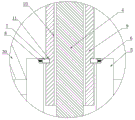
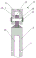
the supporting mechanism comprises a supporting shaft, the bottom of the supporting shaft is rotatably connected with the top of the control base, a fixed pipe is sleeved on the outer side of the supporting shaft, limiting grooves are formed in two sides of the top of an inner cavity of the fixed pipe, arc-shaped clamping plates are arranged inside the limiting grooves, springs are arranged between the arc-shaped clamping plates and the limiting grooves, a connecting shaft is sleeved on the top of the supporting shaft, a connecting hole is formed in the bottom of the connecting shaft, internal threads are formed in the inner wall of the connecting hole, external threads are arranged on the outer side of the supporting shaft, the supporting shaft is in threaded connection with the connecting hole, a limiting clamping groove is formed in the middle of the connecting shaft, the arc-shaped clamping plates are matched with the limiting clamping groove, a connecting substrate is arranged on the top of the connecting shaft, a connecting block is arranged on the top of the connecting substrate, a connecting groove is formed in the bottom of the connecting block, first bolt holes are formed in two sides of the connecting groove and in the middle of the connecting substrate, a first fixing screw is arranged in the first bolt hole, the top of the connecting block is fixedly connected with a mounting substrate, and the mounting substrate is fixedly connected with a solar substrate through a bolt;
the control mechanism comprises a motor, a reduction gearbox is arranged at the output end of the motor, the output end of the reduction gearbox penetrates through the inner wall of the control base and is fixedly connected with the bottom of the supporting shaft, a control circuit board is arranged on one side of the motor, an A/D converter is arranged at the connecting end of the control circuit board, a plurality of light collecting devices are arranged on the two sides of the solar substrate, the connecting end of each light collecting device is connected with the connecting end of the A/D converter, and the control circuit board is electrically connected with the motor.
In a preferred embodiment, the solar panel connection end is connected with a charge and discharge controller, the charge and discharge controller connection end is connected with a storage battery, and the output end of the storage battery is connected with a direct current output wire.
In a preferred embodiment, both sides of the inner wall of the control base are provided with a plurality of heat dissipation holes, the tops of the outer sides of the heat dissipation holes are provided with heat dissipation plates, one side of the motor is provided with a heat dissipation fan, and the heat dissipation fan is electrically connected with the control circuit board.
In a preferred embodiment, a plurality of fixing mechanisms are arranged at the bottom of the solar substrate and on two sides of the fixing pipe, each fixing mechanism comprises two fixing substrates, a plurality of arc-shaped connecting rods are arranged between the solar substrate and the fixing pipe, fixing plates are arranged at two ends of each arc-shaped connecting rod, and a through line groove is formed in the middle of each arc-shaped connecting rod in a penetrating mode.
In a preferred embodiment, a second bolt hole penetrates through the middle of each of the fixing plate and the fixing base plate, and a second fixing screw is arranged inside the second bolt.
In a preferred embodiment, the arc-shaped clamping plate is matched with the limiting clamping groove, and both sides of the top of the control base are provided with through wire holes in a penetrating mode.
In a preferred embodiment, the bottom of the control base is uniformly provided with a plurality of universal wheels, one side of each universal wheel is provided with a limiting mechanism in a matched mode, each limiting mechanism comprises two groups of limiting plates, two groups of fixing plates are arranged on one opposite sides of each limiting plate, guide holes are formed in two sides of each fixing groove on one side of one limiting plate, and guide rods are arranged on two sides of each fixing groove on one side of the other limiting plate.
In a preferred embodiment, the guide rod is matched with the guide hole, push rods are arranged on two sides of the top of the control base, and a handle is arranged at one end of each push rod.
The invention has the technical effects and advantages that:
1. the invention is provided with the supporting mechanism, the connecting shaft is sleeved on the supporting shaft, the arc-shaped clamping plate just enters the limiting clamping groove, the fixing pipe can fix the supporting shaft and the connecting shaft, so as to improve the stability between the supporting shaft and the connecting shaft, the first fixing screw rod is sleeved on the first bolt hole, so that the solar base plate can be rotated to carry out angle adjustment, nuts are screwed on two ends of the first fixing screw rod, so that the angle of the solar base plate can be fixed, the angle of the solar base plate can be freely adjusted when the solar base plate is installed, the assembly is convenient, only the supporting shaft is sleeved on the connecting shaft, the solar base plate is installed, the angle of the solar base plate is adjusted and fixed, the control mechanism is arranged, so that the intensity of illumination can be collected by the light collecting device, the supporting shaft is driven to rotate by the motor, so as to drive the solar base plate to rotate, therefore, the time of the solar cell panel facing the sun is prolonged, the assembly steps are optimized, the use of fixed connection means such as bolts and welding is reduced, the labor intensity during assembly is reduced, and the assembly efficiency is improved;
2. through being provided with fixed establishment, the arc connecting rod is favorable to fixing between solar substrate and the fixed pipe, thereby stability when having improved solar substrate operation, and the inside through-wire groove that is provided with of arc connecting rod, can pass through the through-wire groove with light collection device's electric wire or solar cell panel's electric wire after, in getting into the control base through the through-wire hole, can arrange in order the circuit, the circuit has been optimized, through being provided with stop gear, place a set of stop gear at every universal wheel bottom, make the universal wheel be located between two fixed slots, be close to two limiting plates each other, make guide rod one end get into in the guiding hole, two limiting plates just make up the completion, and the moving range of universal wheel has also been restricted, moreover, the steam generator is simple in structure, high durability and convenient use.
Drawings
Fig. 1 is a schematic view of the overall structure of the present invention.
Fig. 2 is a schematic view of a portion of the structure shown in fig. 1.
Fig. 3 is a sectional view of the structure of the connecting shaft and the connecting block of the present invention.
FIG. 4 is a sectional view of the structure of the arc connecting rod and the fixed substrate of the present invention.
Fig. 5 is a top view of the spacing mechanism of the present invention.
Fig. 6 is a schematic view of a connecting shaft structure of the present invention.
Fig. 7 is a schematic view of a solar energy system of the present invention.
FIG. 8 is a schematic flow chart of the control mechanism system of the present invention.
The reference signs are: the solar energy heat collecting device comprises a control base 1, a solar energy substrate 2, a solar energy cell panel 3, a supporting shaft 4, a fixing tube 5, a limiting groove 6, an arc-shaped clamping plate 7, a spring 8, a connecting shaft 9, a connecting hole 10, a limiting clamping groove 11, a connecting substrate 12, a connecting block 13, a connecting groove 14, a first bolt hole 15, a first fixing screw 16, a mounting substrate 17, a motor 18, a reduction gearbox 19, a control circuit board 20, a 21A/D converter 22, an optical acquisition device 22, a charge and discharge controller 23, a storage battery 24, a direct current output wire 25, a heat dissipation hole 26, a heat dissipation plate 27, a heat dissipation fan 28, a fixing substrate 29, an arc-shaped connecting rod 30, a fixing plate 31, a through groove 32, a second bolt hole 33, a second fixing screw 34, a through hole 35, a universal wheel 36, a limiting plate 37, a fixing groove 38, a guide hole 39, a guide rod 40, a pushing rod 41 and a handle 42.
Detailed Description
The technical solutions in the embodiments of the present invention will be clearly and completely described below with reference to the drawings in the embodiments of the present invention, and it is obvious that the described embodiments are only a part of the embodiments of the present invention, and not all of the embodiments. All other embodiments, which can be derived by a person skilled in the art from the embodiments given herein without making any creative effort, shall fall within the protection scope of the present invention.
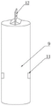
The solar photovoltaic direct current assembly and the solar power generation system shown in fig. 1, fig. 2, fig. 3, fig. 6 and fig. 7 comprise a control base 1, wherein a control mechanism is arranged inside the control base 1, a supporting mechanism is arranged at the top of the control mechanism, a solar substrate 2 is arranged at the top of the supporting mechanism, and a plurality of solar panels 3 are arranged at the top of the solar substrate 2;
the supporting mechanism comprises a supporting shaft 4, the bottom of the supporting shaft 4 is rotatably connected with the top of a control base 1, a fixed pipe 5 is sleeved on the outer side of the supporting shaft 4, limiting grooves 6 are respectively arranged on two sides of the top of an inner cavity of the fixed pipe 5, an arc-shaped clamping plate 7 is arranged inside the limiting grooves 6, a spring 8 is arranged between the arc-shaped clamping plate 7 and the limiting grooves 6, a connecting shaft 9 is sleeved on the top of the supporting shaft 4, a connecting hole 10 is arranged at the bottom of the connecting shaft 9, inner threads are arranged on the inner wall of the connecting hole 10, external threads are arranged on the outer side of the supporting shaft 4, the supporting shaft 4 is in threaded connection with the connecting hole 10, a limiting clamping groove 11 is arranged in the middle of the connecting shaft 9, the arc-shaped clamping plate 7 is matched with the limiting clamping groove 11, a connecting substrate 12 is arranged on the top of the connecting shaft 9, a connecting block 13 is arranged on the top of the connecting substrate 12, and a connecting groove 14 is arranged on the bottom of the connecting block 13, first bolt holes 15 penetrate through two sides of the connecting groove 14 and the middle of the connecting base plate 12, first fixing screws 16 are arranged in the first bolt holes 15, the top of the connecting block 13 is fixedly connected with a mounting base plate 17, and the mounting base plate 17 is fixedly connected with the solar base plate 2 through bolts;
the solar cell panel 3 is connected with a charge and discharge controller 23 at the connecting end, the charge and discharge controller 23 is connected with a storage battery 24 at the connecting end, and the output end of the storage battery 24 is connected with a direct current output wire 25;
arc cardboard 7 and spacing draw-in groove 11 phase-match, control base 1 top both sides all run through and are provided with through-wire hole 35.
The implementation mode is specifically as follows: when the solar panel is used, the control base 1 is pushed to move the control base 1 to a proper position, then the connecting hole 10 at the bottom of the connecting shaft 9 is aligned with the supporting shaft 4 and pushed downwards, so that the connecting shaft 9 is sleeved on the supporting shaft 4, when the connecting shaft 9 is sleeved on the supporting shaft 4, the bottom of the connecting shaft 9 is contacted with the arc-shaped clamping plate 7, the arc-shaped clamping plate 7 is continuously pushed to extrude the inner spring 8, so that the connecting shaft 9 can smoothly move downwards, when the top end of the supporting shaft 4 is contacted with the top of an inner cavity of the connecting hole 10, the arc-shaped clamping plates 7 at two sides just enter the limiting clamping groove 11 at the middle part of the connecting shaft 9, the fixing pipe 5 can fix the supporting shaft 4 and the connecting shaft 9, so as to improve the stability between the supporting shaft 4 and the connecting shaft 9, when the solar panel 2 is arranged on the mounting base plate 17, the first fixing screw 16 is sleeved on the first bolt hole 15, when the solar substrate 2 is rotated, the solar substrate 2 can rotate by taking the first fixing screw 16 as an axis, when the solar substrate 2 is rotated to a proper angle, nuts can be screwed on two ends of the first fixing screw 16, so that the connecting block 13 and the connecting clamping plate can be fixed, the angle of the solar substrate 2 is fixed, the solar module is assembled, the solar panel 3 can absorb solar energy and transmit the solar energy to the charge and discharge controller 23, the solar energy is converted by the charge and discharge controller 23 and transmitted to the storage battery 24, the storage battery 24 can supply power to an electric appliance using direct current through the direct current output wire 25, the angle of the solar substrate 2 can be freely adjusted when the solar module is installed, the assembly is convenient and fast, only the connecting shaft 9 needs to be sleeved on the supporting shaft 4, the solar substrate 2 is installed, and the angle of the solar substrate 2 is adjusted and fixed, the assembling steps are optimized, the use of fixing means such as bolts and welding is reduced, the labor intensity during assembling is reduced, and the assembling efficiency is improved.
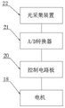
According to the solar photovoltaic direct current assembly and the solar power generation system shown in fig. 1 and 8, the control mechanism comprises a motor 18, a reduction gearbox 19 is arranged at the output end of the motor 18, the output end of the reduction gearbox 19 penetrates through the inner wall of the control base 1 and is fixedly connected with the bottom of the support shaft 4, a control circuit board 20 is arranged on one side of the motor 18, an A/D converter 21 is arranged at the connecting end of the control circuit board 20, a plurality of light collecting devices 22 are arranged on two sides of the solar base plate 2, the connecting ends of the light collecting devices 22 are connected with the connecting end of the A/D converter 21, and the control circuit board 20 is electrically connected with the motor 18;
the control base 1 is characterized in that a plurality of heat dissipation holes 26 are formed in two sides of the inner wall of the control base 1, heat dissipation plates 27 are arranged on the tops of the outer sides of the heat dissipation holes 26, a heat dissipation fan 28 is arranged on one side of the motor 18, and the heat dissipation fan 28 is electrically connected with the control circuit board 20.
The implementation mode is specifically as follows: when the solar module is used, when the solar module is assembled, the light collection device 22 can collect the illumination intensity and transmit the illumination intensity to the control circuit board 20, after the control circuit board 20 analyzes, the control motor 18 drives the support shaft 4 to rotate through the reduction gearbox 19, and the support shaft 4 rotates to drive the solar substrate 2 to rotate, so that the time of the solar panel 3 facing the solar illumination is prolonged, and the collection efficiency of the solar panel 3 is improved.
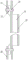
According to the solar photovoltaic direct current assembly and the solar power generation system shown in fig. 1, 4 and 5, a plurality of fixing mechanisms are arranged at the bottom of the solar substrate 2 and at two sides of the fixing pipe 5, each fixing mechanism comprises two fixing substrates 29, a plurality of arc-shaped connecting rods 30 are arranged between the solar substrate 2 and the fixing pipe 5, fixing plates 31 are arranged at two ends of each arc-shaped connecting rod 30, and a through line groove 32 is arranged in the middle of each arc-shaped connecting rod 30 in a penetrating manner;
a second bolt hole 33 penetrates through the middle parts of the fixing plate 31 and the fixing base plate 29, and a second fixing screw 34 is arranged in the second bolt;
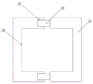
the bottom of the control base 1 is uniformly provided with a plurality of universal wheels 36, one side of each universal wheel 36 is provided with a limiting mechanism in a matched mode, each limiting mechanism comprises two groups of limiting plates 37, one opposite side of each limiting plate 37 is provided with a fixing groove 38, two sides of the fixing groove 38 on one side of one limiting plate 37 are provided with guide holes 39, and two sides of the fixing groove 38 on one side of the other limiting plate 37 are provided with guide rods 40;
the guide rod 40 is matched with the guide hole 39, the pushing rods 41 are arranged on two sides of the top of the control base 1, and a handle 42 is arranged at one end of each pushing rod 41.
The implementation mode is specifically as follows: when the solar panel angle adjusting device is used, after the angle of the solar substrate 2 is fixed, a proper arc-shaped connecting rod 30 is selected and is placed between the fixed substrate 29 at the bottom of the solar substrate 2 and the fixed substrate 29 at one side of the fixed pipe 5, the second fixing screw 34 is inserted into the corresponding second bolt hole 33, and nuts are screwed at two ends of the second fixing screw 34, so that the arc-shaped connecting rod 30 can fix the solar substrate 2 and the fixed pipe 5, the stability of the solar substrate 2 is improved, the through-line groove 32 is arranged in the arc-shaped connecting rod 30, wires of the light collecting device or the solar panel 3 can enter the control base 1 through the through-line groove 32 after passing through the through-line hole 35, the wires can be arranged, the wires are optimized, and the universal wheels 36 are arranged at the bottom of the control base 1, even after the assembly is finished, the handle 42 can be held to push the control base 1 to move, so that the solar substrate 2 can be moved, and when the movement is not needed, the movement is only needed.
The working principle of the invention is as follows:
referring to the attached drawings 1, 2, 3, 6 and 7 of the specification, when the solar panel is used, the control base 1 is pushed to move the control base 1 to a proper position, then the connecting hole 10 at the bottom of the connecting shaft 9 is aligned with the supporting shaft 4 and pushed downwards to enable the connecting shaft 9 to be sleeved on the supporting shaft 4, when the connecting shaft 9 is sleeved on the supporting shaft 4, the bottom of the connecting shaft 9 can be contacted with the arc-shaped clamping plate 7 and pushed continuously to enable the arc-shaped clamping plate 7 to extrude the spring 8 inside, so that the connecting shaft 9 can move downwards smoothly, when the top end of the supporting shaft 4 is contacted with the top of the inner cavity of the connecting hole 10, the arc-shaped clamping plates 7 at two sides just enter the limiting clamping grooves 11 in the middle of the connecting shaft 9, the fixing pipe 5 can fix the supporting shaft 4 and the connecting shaft 9, when the solar panel 2 is installed on the installation substrate 17, the first bolt hole 15 is sleeved with the first fixing screw 16, when the solar substrate 2 is rotated, the solar substrate 2 can rotate by taking the first fixing screw 16 as an axis, when the solar substrate is rotated to a proper angle, nuts can be screwed on two ends of the first fixing screw 16, so that the connecting block 13 and the connecting clamp plate can be fixed, the angle of the solar substrate 2 is fixed, the solar module is assembled, the solar panel 3 can absorb solar energy and transmit the solar energy to the charge and discharge controller 23, the solar energy is converted by the charge and discharge controller 23 and then transmitted to the storage battery 24, and the storage battery 24 can supply power to an electric appliance using direct current through the direct current output wire 25;
referring to the attached drawings 1 and 8 of the specification, when the solar module is assembled in use, the light collection device 22 can collect the illumination intensity and transmit the illumination intensity to the control circuit board 20, after the control circuit board 20 analyzes the illumination intensity, the control motor 18 drives the support shaft 4 to rotate through the reduction box 19, and the support shaft 4 rotates to drive the solar substrate 2 to rotate;
referring to the attached drawings 1, 4 and 5 of the specification, when the invention is used, after the angle of the solar substrate 2 is fixed, a proper arc-shaped connecting rod 30 is selected and placed between the fixed substrate 29 at the bottom of the solar substrate 2 and the fixed substrate 29 at one side of the fixed pipe 5, a second fixing screw 34 is inserted into a corresponding second bolt hole 33, and nuts are screwed on both ends of the second fixing screw 34, so that the arc-shaped connecting rod 30 can fix the solar substrate 2 and the fixed pipe 5, thereby improving the stability of the solar substrate 2, and the arc-shaped connecting rod 30 is internally provided with a through-wire groove 32, so that the electric wire of the light collecting device or the electric wire of the solar panel 3 can enter the control base 1 through the through-wire groove 35 after passing through the through-wire groove 32, and the bottom of the control base 1 is provided with a plurality of universal wheels 36, even after the assembly is completed, the handle 42 can be held to push the control base 1 to move, so that the solar substrate 2 can be moved, and when the movement is not needed, only a group of limiting mechanisms are placed at the bottom of each universal wheel 36 to limit the moving range of the universal wheels 36.
The points to be finally explained are: first, in the description of the present application, it should be noted that, unless otherwise specified and limited, the terms "mounted," "connected," and "connected" should be understood broadly, and may be a mechanical connection or an electrical connection, or a communication between two elements, and may be a direct connection, and "upper," "lower," "left," and "right" are only used to indicate a relative positional relationship, and when the absolute position of the object to be described is changed, the relative positional relationship may be changed;
secondly, the method comprises the following steps: in the drawings of the disclosed embodiments of the invention, only the structures related to the disclosed embodiments are referred to, other structures can refer to common designs, and the same embodiment and different embodiments of the invention can be combined with each other without conflict;
and finally: the above description is only for the purpose of illustrating the preferred embodiments of the present invention and is not to be construed as limiting the invention, and any modifications, equivalents, improvements and the like that are within the spirit and principle of the present invention are intended to be included in the scope of the present invention.