CN110470879B - Contactless direct voltage measuring device with oscillation sensor - Google Patents
Contactless direct voltage measuring device with oscillation sensor Download PDFInfo
- Publication number
- CN110470879B CN110470879B CN201910389076.0A CN201910389076A CN110470879B CN 110470879 B CN110470879 B CN 110470879B CN 201910389076 A CN201910389076 A CN 201910389076A CN 110470879 B CN110470879 B CN 110470879B
- Authority
- CN
- China
- Prior art keywords
- sensor
- conductive
- current
- voltage
- insulated conductor
- Prior art date
- Legal status (The legal status is an assumption and is not a legal conclusion. Google has not performed a legal analysis and makes no representation as to the accuracy of the status listed.)
- Active
Links
Images


Classifications
-
- G—PHYSICS
- G01—MEASURING; TESTING
- G01R—MEASURING ELECTRIC VARIABLES; MEASURING MAGNETIC VARIABLES
- G01R31/00—Arrangements for testing electric properties; Arrangements for locating electric faults; Arrangements for electrical testing characterised by what is being tested not provided for elsewhere
- G01R31/28—Testing of electronic circuits, e.g. by signal tracer
- G01R31/302—Contactless testing
-
- G—PHYSICS
- G01—MEASURING; TESTING
- G01R—MEASURING ELECTRIC VARIABLES; MEASURING MAGNETIC VARIABLES
- G01R1/00—Details of instruments or arrangements of the types included in groups G01R5/00 - G01R13/00 and G01R31/00
- G01R1/02—General constructional details
- G01R1/04—Housings; Supporting members; Arrangements of terminals
-
- G—PHYSICS
- G01—MEASURING; TESTING
- G01R—MEASURING ELECTRIC VARIABLES; MEASURING MAGNETIC VARIABLES
- G01R1/00—Details of instruments or arrangements of the types included in groups G01R5/00 - G01R13/00 and G01R31/00
- G01R1/20—Modifications of basic electric elements for use in electric measuring instruments; Structural combinations of such elements with such instruments
- G01R1/22—Tong testers acting as secondary windings of current transformers
-
- G—PHYSICS
- G01—MEASURING; TESTING
- G01R—MEASURING ELECTRIC VARIABLES; MEASURING MAGNETIC VARIABLES
- G01R15/00—Details of measuring arrangements of the types provided for in groups G01R17/00 - G01R29/00, G01R33/00 - G01R33/26 or G01R35/00
- G01R15/12—Circuits for multi-testers, i.e. multimeters, e.g. for measuring voltage, current, or impedance at will
-
- G—PHYSICS
- G01—MEASURING; TESTING
- G01R—MEASURING ELECTRIC VARIABLES; MEASURING MAGNETIC VARIABLES
- G01R15/00—Details of measuring arrangements of the types provided for in groups G01R17/00 - G01R29/00, G01R33/00 - G01R33/26 or G01R35/00
- G01R15/14—Adaptations providing voltage or current isolation, e.g. for high-voltage or high-current networks
- G01R15/16—Adaptations providing voltage or current isolation, e.g. for high-voltage or high-current networks using capacitive devices
-
- G—PHYSICS
- G01—MEASURING; TESTING
- G01R—MEASURING ELECTRIC VARIABLES; MEASURING MAGNETIC VARIABLES
- G01R19/00—Arrangements for measuring currents or voltages or for indicating presence or sign thereof
- G01R19/0084—Arrangements for measuring currents or voltages or for indicating presence or sign thereof measuring voltage only
-
- G—PHYSICS
- G01—MEASURING; TESTING
- G01R—MEASURING ELECTRIC VARIABLES; MEASURING MAGNETIC VARIABLES
- G01R31/00—Arrangements for testing electric properties; Arrangements for locating electric faults; Arrangements for electrical testing characterised by what is being tested not provided for elsewhere
- G01R31/28—Testing of electronic circuits, e.g. by signal tracer
- G01R31/2851—Testing of integrated circuits [IC]
- G01R31/2855—Environmental, reliability or burn-in testing
- G01R31/2872—Environmental, reliability or burn-in testing related to electrical or environmental aspects, e.g. temperature, humidity, vibration, nuclear radiation
- G01R31/2879—Environmental, reliability or burn-in testing related to electrical or environmental aspects, e.g. temperature, humidity, vibration, nuclear radiation related to electrical aspects, e.g. to voltage or current supply or stimuli or to electrical loads
Abstract
The present invention provides systems and methods for measuring the Direct Current (DC) voltage of an insulated conductor (e.g., an insulated wire) without requiring an electrical connection between the conductor and a test electrode or probe. A contactless DC voltage measurement device may include a mechanically oscillating conductive sensor. The insulated conductor to be tested serves as a first conductive element or electrode of a coupling capacitor and the vibrating conductive sensor serves as a second conductive element or electrode of the coupling capacitor. Oscillation of the conductive sensor provides a time-varying capacitance value for the coupling capacitor. The measurement device detects a current flowing through the coupling capacitor and determines the DC voltage in the insulated conductor using the detected current and the time-varying capacitance. The determined DC voltage may be output to a display or transmitted to an external system via a wired or wireless connection.
Description
Background of the invention is described.
Technical Field
The present disclosure relates generally to measurement of electrical characteristics, and more particularly, to non-contact measurement of direct current voltage (DC).
Background
A voltmeter is an instrument used to measure voltage in an electrical circuit. Instruments that measure more than one electrical characteristic are called multimeters or digital multimeters (DMMs) and are used to measure many parameters that are typically required for service, troubleshooting, and maintenance applications. Such parameters typically include Alternating Current (AC) voltage and current, direct Current (DC) voltage and current, and resistance or on-off. Other parameters, such as power characteristics, frequency, capacitance, and temperature, may also be measured to meet the requirements of a particular application.
For a conventional voltmeter or multimeter measuring DC voltage, it is necessary to bring at least one measuring electrode or probe into electrical contact with a conductor, which usually requires cutting off a portion of the insulation of the insulated wire or providing a measuring terminal in advance. In addition to requiring exposed wires or terminals to make electrical contact, the step of contacting the voltmeter probe to a stripped wire or terminal can be quite dangerous because of the risk of electrical shock or electrocution.
Therefore, there is a need for a DC voltage measuring device that provides convenient and accurate voltage measurement without the need for electrical contact with the circuit under test.
Disclosure of Invention
An apparatus for measuring a direct current (AC) voltage in an insulated conductor may be summarized as including: a housing; a conductive sensor physically coupled to the housing, the conductive sensor being selectively positionable proximate to the insulated conductor without making electrical contact with the insulated conductor, wherein the conductive sensor is capacitively coupled to the insulated conductor; a conductive internal ground shield at least partially surrounding and electrically isolated from the conductive sensor, the internal ground shield being sized and dimensioned to protect the conductive sensor from stray currents; a conductive reference shield surrounding at least a portion of the housing and electrically insulated from the internal ground shield, the conductive reference shield being sized and dimensioned to reduce current flow between the internal ground shield and the external ground; a mechanical oscillator operatively coupled to the conductive sensor, the mechanical oscillator, in operation, mechanically oscillating the conductive sensor according to a mechanical oscillation amplitude and a mechanical oscillation frequency such that a distance between the conductive sensor and the insulated conductor periodically varies according to the mechanical oscillation amplitude and the mechanical oscillation frequency; a common mode reference voltage source that, in operation, generates an Alternating Current (AC) reference voltage having a reference frequency, the common mode reference voltage source being electrically coupled between the internal ground guard and the conductive reference shield; a sensor signal measurement subsystem electrically coupled to the electrically conductive sensor, wherein the sensor signal measurement subsystem, in operation, generates a sensor current signal indicative of a current conducted through the electrically conductive sensor; and control circuitry communicatively coupled to the sensor signal measurement subsystem, wherein in operation the control circuitry: receiving a sensor current signal from a sensor signal measurement subsystem; and determining a DC voltage in the insulated conductor based at least in part on the received sensor current signal. The control circuit may determine a DC voltage in the insulated conductor based at least in part on the received sensor current signal, the mechanical oscillation frequency, the AC reference voltage, and the reference frequency. The mechanical oscillator may comprise a piezoelectric effect mechanical oscillator. The mechanical oscillator may comprise a microelectromechanical (MEMS) mechanical oscillator.
The control circuit is operable to convert the received sensor current signal to a digital signal; and processing the digital signal to obtain a frequency domain representation of the sensor current signal. The control circuitry may implement a Fast Fourier Transform (FFT) to obtain a frequency domain representation of the sensor current signal. The common mode reference voltage source may generate an AC reference voltage that is in phase with the window of the FFT implemented by the control circuit. The control circuit may include at least one electronic filter that filters the received sensor current signal. The control circuit may process the sensor current signal to determine an insulated conductor current component indicative of current conducted through the conductive sensor due to voltage in the insulated conductor and a reference current component indicative of current conducted through the conductive sensor due to voltage of the common mode reference voltage source. The control circuit may determine a frequency of the determined insulated conductor current component of the sensor current signal. In operation, the sensor signal measurement subsystem may receive an input current from the conductive sensor, and the sensor current signal may include a voltage signal indicative of the input current received from the conductive sensor. The sensor signal measurement subsystem may include an operational amplifier operating as a current-to-voltage converter.
A method of operating an apparatus to measure a Direct Current (DC) voltage in an insulated conductor, the apparatus comprising: a housing; a conductive sensor physically coupled to the housing, the conductive sensor being selectively positionable proximate the insulated conductor without making electrical contact with the conductor; a conductive internal ground shield at least partially surrounding and electrically isolated from the conductive sensor, wherein the internal ground shield is sized and dimensioned to protect the conductive sensor from stray currents; a conductive reference shield surrounding at least a portion of the housing and electrically insulated from the internal ground shield, wherein the conductive reference shield is sized and dimensioned to reduce current flow between the internal ground shield and the external ground, the method may be summarized as including mechanically oscillating the conductive sensor according to a mechanical oscillation amplitude and a mechanical oscillation frequency such that a distance between the conductive sensor and the insulated conductor varies periodically according to the mechanical oscillation amplitude and the mechanical oscillation frequency; causing a common mode reference voltage source to generate an Alternating Current (AC) reference voltage having a reference frequency, the common mode reference voltage source being electrically coupled between the internal ground guard and the conductive reference shield; generating, by a sensor signal measurement subsystem, a sensor current signal indicative of a current conducted through the conductive sensor; receiving, by the control circuit, a sensor current signal from the sensor signal measurement subsystem; and determining, by the control circuit, a DC voltage in the insulated conductor based at least in part on the received sensor current signal.
Generating the sensor current signal may include receiving an input current from a conductive sensor; and generating a voltage signal indicative of the input current received from the conductive sensor. The sensor current signal may be generated using an operational amplifier operating as a current-to-voltage converter. Mechanically oscillating the conductive sensor may include mechanically oscillating the conductive sensor using a piezoelectric effect mechanical oscillator. Mechanically oscillating the conductive sensor may include mechanically oscillating the conductive sensor using a microelectromechanical (MEMS) mechanical oscillator.
Determining the DC voltage in the insulated conductor may include converting, by the at least one processor, the received sensor current signal to a digital signal; and processing the digital signal by at least one processor to obtain a frequency domain representation of the sensor current signal. Processing the digital signal may include implementing a Fast Fourier Transform (FFT) to obtain a frequency domain representation of the sensor current signal. Determining the DC voltage in the insulated conductor may include electronically filtering the received sensor current signal.
An apparatus for measuring Direct Current (DC) voltage in an insulated conductor may be summarized as including: a conductive sensor selectively positionable proximate to the insulated conductor without making electrical contact therewith, wherein the conductive sensor is capacitively coupled to the insulated conductor; a mechanical oscillator operatively coupled to the conductive sensor, the mechanical oscillator, in operation, mechanically oscillating the conductive sensor to vary a capacitance between the conductive sensor and the insulated conductor with respect to time; a conductive inner ground shield at least partially surrounding and electrically isolated from the conductive sensor; a conductive reference shield surrounding at least a portion of the housing and electrically insulated from the internal ground shield; a common mode reference voltage source that generates an Alternating Current (AC) reference voltage having a reference frequency in operation, the common mode reference voltage source being electrically coupled between the internal ground guard and the conductive reference shield; a sensor signal measurement subsystem electrically coupled to the electrically conductive sensor, wherein the sensor signal measurement subsystem, in operation, generates a sensor current signal indicative of a current conducted through the electrically conductive sensor; and control circuitry communicatively coupled to the sensor signal measurement subsystem, wherein in operation the control circuitry: receiving a sensor current signal from a sensor signal measurement subsystem; and determining a DC voltage in the insulated conductor based at least in part on the received sensor current signal. In operation, the control circuit may determine a DC voltage in the insulated conductor based on the received sensor current signal and based on a change in capacitance between the conductive sensor and the insulated conductor with respect to time. The mechanical oscillator may include at least one of a piezoelectric effect mechanical oscillator or a microelectromechanical (MEMS) mechanical oscillator.
Drawings
In the drawings, like reference numbers indicate similar elements or acts. The sizes and relative positions of elements in the drawings are not necessarily drawn to scale. For example, the shapes of various elements and angles are not necessarily drawn to scale, and some of these elements may be arbitrarily enlarged and positioned to improve drawing legibility. Further, the particular shapes of the elements as drawn, are not necessarily intended to convey any information regarding the actual shape of the particular elements, and may have been solely selected for ease of recognition in the drawings.
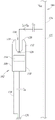
Fig. 1A is a schematic diagram of an environment in which an operator may use a contactless DC voltage measurement device to measure a DC voltage present in an insulated wire without requiring electrical contact with the wire, according to one illustrated implementation.
Fig. 1B is a top view of the contactless DC voltage measurement device of fig. 1A, showing a coupling capacitance formed between an insulated wire and a conductive sensor of the contactless voltage measurement device, according to one illustrated implementation.
Fig. 2 is a schematic diagram of various internal components of a contactless DC voltage measurement apparatus according to one illustrated implementation.
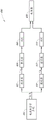
Fig. 3 is a block diagram illustrating various signal processing components of a contactless DC voltage measurement device, according to one illustrated implementation.
Fig. 4 is a block diagram of a contactless DC voltage measurement device implementing an analog electronic filter according to an example of signal and reference signal separation.
Detailed Description
One or more implementations of the present disclosure relate to systems and methods for measuring DC voltage in an insulated conductor or uninsulated bare conductor (e.g., insulated wire) without requiring an electrical connection between the conductor and a test electrode or probe. Generally, a non-electrical contact (or "non-contact") voltage measuring device is provided that uses a vibrating capacitive sensor to measure a DC voltage signal in an insulated conductor relative to ground. Such devices that do not require electrical connections are referred to herein as "contactless. As used herein, "electrically coupled" includes both direct and indirect electrical coupling, unless otherwise specified.
As an overview, a contactless DC voltage measurement device may include a contactless conductive sensor (e.g., a conductive film) that mechanically oscillates or vibrates using a suitable oscillator (e.g., a piezoelectric effect oscillator, a micro-mechanical system (MEMS) oscillator). The conductive sensor may be positioned in close proximity to the insulated conductor to be measured, e.g., within a few millimeters of the insulated conductor. To obtain the measurement, the insulated conductor to be measured is used as a first conductive element or electrode of a coupling capacitor, and the vibrating conductive sensor is used as a second conductive element or electrode of the coupling capacitor. The capacitance of the resulting coupling capacitor changes with respect to time due to vibration of the sensor, due toThe distance between the sensor and the conductor to be measured is variable for the vibrations. The contactless DC voltage measurement device comprises a device for detecting or measuring an AC current flowing through a coupling capacitor due to vibrations, herein referred to as signal current (I) O ). The AC signal current is proportional to the DC voltage across the coupling capacitor and the time-varying change in capacitance of the coupling capacitor caused by vibration of the non-contact conductive sensor. The DC voltage measurement device uses a known reference voltage that produces a reference current and the AC voltage of the vibrating contactless sensor (e.g., 0 volts or ground) to determine the DC voltage across the coupling capacitor using the detected signal current produced by the vibration.
The determined DC voltage in the insulated conductor may be output to a user (e.g., via a display) or may be transmitted to an external system over one or more wired or wireless connections. In addition to DC voltage, the measurement devices discussed herein may also include functionality for determining other electrical parameters, such as, but not limited to, AC voltage, AC or DC current, power, phase angle, waveform, thermal characteristics, impedance, and the like.
In the following description, certain specific details are set forth in order to provide a thorough understanding of various implementations disclosed. One skilled in the relevant art will recognize, however, that the embodiments may be practiced without one or more of the specific details, or with other methods, components, materials, and so forth. In other instances, well-known structures associated with computer systems, server computers, and/or communication networks have not been shown or described in detail to avoid unnecessarily obscuring descriptions of these specific implementations.
Unless the context requires otherwise, throughout the description and the claims, the word "comprise" and "comprises" are synonymous and are inclusive or open-ended (i.e., do not exclude additional unrecited elements or method acts).
Reference throughout this specification to "one implementation" or "an implementation" means that a particular feature, structure, or characteristic described in connection with the implementation is included in at least one implementation. Thus, the appearances of the phrases "in one embodiment" or "in an embodiment" in various places throughout this specification are not necessarily all referring to the same embodiment. Furthermore, the particular features, structures, or characteristics may be combined in any suitable manner in one or more implementations.
As used in this specification and the appended claims, the singular forms "a," "an," and "the" include plural referents unless the context clearly dictates otherwise. It should also be noted that the term "or" is generally employed in its sense including "and/or" unless the context clearly dictates otherwise.
The headings and abstract of the specification provided herein are provided for convenience only and do not interpret the scope or meaning of the specific implementations.
Fig. 1A is a schematic illustration of an environment 100 in which an operator 104 may use a contactless DC voltage measurement device 102 of the present disclosure to measure a DC voltage present in an insulated electrical wire 106 without requiring electrical contact between the contactless voltage measurement device and the electrical wire 106. Fig. 1B is a top view of the contactless voltage measurement device 102 of fig. 1A, illustrating various electrical characteristics of the contactless DC voltage measurement device during operation. The non-contact voltage measurement device 102 includes a housing or body 108 that includes a grip portion or end 110 and a probe portion or end 112 (also referred to herein as a front end) opposite the grip portion. The housing 108 may also include a user interface 114 that facilitates user interaction with the contactless voltage measurement device 102. The user interface 114 may include any number of inputs (e.g., buttons, dials, switches, touch sensors) and any number of outputs (e.g., display, LED, speaker, buzzer). The contactless voltage measurement device 102 may also include one or more wired and/or wireless communication interfaces (e.g., USB, wi-Fi) ® 、Bluetooth ® ) And various control or processing circuits (e.g., processors, microcontrollers, DSPs, ASICs, FPGAs, memories).
In at least some implementations, as best shown in fig. 1B, the probe portion 112 can include a recessed portion 116 defined by a first extension 118 and a second extension 120. The recessed portion 116 receives the insulated wire 106 (see fig. 1A). The insulated wire 106 includes a conductor 122 and an insulator 124 surrounding the conductor 122. When the insulated wire 106 is positioned within the recessed portion 116 of the noncontact voltage measurement device 102, the recessed portion 116 can include a noncontact conductive sensor or electrode 126 positioned adjacent to the insulator 124 of the insulated wire. The sensor 126 may be positioned within the interior or recessed location of the housing 108 to prevent physical and electrical contact between the sensor and other objects. As discussed further below, in operation, the conductivity sensor 126 mechanically oscillates during the measurement process, which allows the measurement device 102 to accurately measure the DC voltage in the insulated conductor 106 to be measured.
As shown in fig. 1A, in use, the operator 104 can grasp the gripping portion 110 of the housing 108 and place the probe portion 112 proximate to the insulated wire 106 so that the contactless voltage measurement device 102 can accurately measure the DC voltage present in the wire relative to ground (or another reference node). Although the probe end portion 112 is shown with the recessed portion 116, in other implementations, the probe portion 112 may be configured differently. For example, in at least some implementations, the probe portion 112 can include a selectively movable clamp, hook, flat or arcuate surface that includes a sensor, or other type of interface that allows the sensor of the non-contact voltage measurement device 102 to be positioned proximate to the insulated wire 106.
It may only be possible in certain implementations to have the operator's body act as a ground/earth reference. Alternatively, a direct connection to ground 128 via test leads 139 may be used. The non-contact measurement functionality discussed herein is not limited to applications with respect to only ground measurements. The external reference may be capacitively coupled or directly coupled to any other potential. For example, if an external reference capacitance is coupled to another phase in a three-phase system, the phase-to-phase voltages are measured. In general, the concepts discussed herein are not limited to using only bulk capacitive coupling connected to a reference voltage and any other reference potential to reference with respect to ground.
As discussed further below, at leastIn some implementations, the noncontact voltage measurement device 102 can utilize the bulk capacitance (C) between the operator 104 and the ground 128 during DC voltage measurement B ). Although the term "ground" is used for node 128, this node need not be ground/ground, but may be connected to any other reference potential in an electrically isolated manner by capacitive coupling. Measurement device 102 can also be coupled to a reference node, such as node 128, by a conventional electrical coupling (e.g., a test lead).
Fig. 2 shows a schematic diagram of various internal components of the contactless voltage measurement device 102, also shown in fig. 1A and 1B. In this example, the conductive sensor 126 of the non-contact voltage measurement device 102 is shaped in the form of a plate or film and is positioned proximate to the insulated wire 106 under test and capacitively couples with the conductor 122 of the insulated wire 106, forming a sensor coupling capacitor (C) O ). It should be understood that the conductive sensor may be other planar shapes (e.g., circular, rectangular, triangular) or non-planar shapes (e.g., V-shaped, U-shaped). The operator 104 who operates the contactless DC voltage measurement device 102 has a capacitance (C) to the earth's body B ). As shown in fig. 1A and 1B, direct conductive ground coupling through a wire (e.g., test lead 139) may also be used. Based on the DC voltage signal (V) in conductor 122, as discussed further below DC ) And mechanical oscillations induced in the sensor 126, coupling capacitors (C) in series connection O ) The sum body Capacitance (CB) produces an insulated conductor current component or 'signal current' (I) O ). In some implementations, the bulk capacitance (C) B ) A test lead that generates electrical isolation of capacitance to ground or any other reference potential may also be included.
DC Voltage (V) in wire 122 to be measured DC ) With a connection to external ground 128 (e.g., neutral). The noncontact voltage measurement device 102 itself also has a capacitance to ground 128, which is primarily due to the bulk capacitance (C) when the operator 104 (FIG. 1) holds the noncontact voltage measurement device in his hand B ) And (4) forming. Capacitor C O And C B Both form a conductive loop, and the voltage in the loopGenerating a signal current (I) O ). Signal current (I) O ) By a DC voltage signal (V) capacitively coupled to the conductive sensor 126 DC ) Generated and passed through the housing 108 of the contactless DC voltage measurement device and the bulk capacitor to ground 128 (C) B ) Looping back to external ground 128. Signal current (I) O ) Depending on the distance between the conductive sensor 126 of the noncontact voltage measurement device 102 and the insulated wire 106 under test, the particular shape of the conductive sensor 126, and the size and voltage level (V) of the conductor 122 DC )。
In order to compensate for directly influencing the signal current (I) O ) And the consequent coupling capacitor (C) O ) Variance, noncontact voltage measurement device 102 includes a common-mode reference voltage source 130 that generates a reference voltage having a frequency (f) related to a mechanical oscillation O ) Different reference frequencies (f) R ) AC reference voltage (V) R ) As described below.
To reduce or avoid stray currents, at least a portion of the non-contact voltage measurement device 102 may be surrounded by a conductive internal ground shield or shroud 132, which allows most of the current to flow through the conductors 122 that form coupling capacitors (C) with the insulated electrical wires 106 O ) The conductive sensor 126. The internal ground guard 132 may be formed of any suitable conductive material (e.g., copper) and may be solid (e.g., foil) or have one or more openings (e.g., mesh). The shield 132 surrounding the sensor 126 also reduces stray effects of adjacent wires near the sensor 126 during measurement.
The noncontact voltage measurement device 102 includes a mechanical oscillator 144 electrically coupled to the conductive sensor 126. In operation, the mechanical oscillator 144 causes the conductive sensor 126 to oscillate according to the mechanical oscillation amplitude and the mechanical oscillation frequency (f) O ) Mechanical oscillation is performed. The mechanical oscillator 144 oscillates the conductive sensor 126 in the direction of the insulated conductor 106 to be measured such that the distance (d) between the conductive sensor 126 and the insulated conductor 106 varies periodically according to the mechanical oscillation amplitude and the mechanical oscillation frequency. The mechanical oscillation changes the coupling capacitor (C) exposed to the electric field O ) The value of (c). Thus, at the sensor 126Therein generating a signal having an oscillation frequency (f) O ) Signal current (I) of O ). The current is proportional to the electric field. As described below, the common mode reference source 130 is used to utilize a frequency (f) different from the oscillation frequency (f) O ) Is injected into the sensor with a known frequency (f) R ) Sum amplitude (V) R ) And generating a reference current I R . Therefore, it can be independent of the coupling capacitor C according to equation (1) O To determine the unknown DC voltage in the conductor 106 under test, as described below.
To avoid current flow between the internal ground guard 132 and the external ground 128, the noncontact voltage measurement device 102 includes a conductive reference shield 134. The reference shield 134 may be formed of any suitable conductive material (e.g., copper) and may be solid (e.g., sheet metal, sputtered metal within a plastic housing), flexible (e.g., foil) or have one or more openings (e.g., mesh). The common mode reference voltage source 130 is electrically coupled between the reference shield 134 and the internal ground guard 132, which may generate a reference voltage (V) for the contactless DC voltage measurement device 102 R ) And a reference frequency (f) R ) Or a reference signal. Such AC reference voltage (V) R ) Driving an additional reference current (I) R ) Through a coupling capacitor (C) O ) Bulk capacitor (C) B )。
An internal ground guard 132 surrounding at least a portion of the conductive sensor 126 protects the conductive sensor from an AC reference voltage (V) R ) Resulting in a reference current (I) between the conductive sensor 126 and the reference shield 134 R ) An undesirable shift occurs. As described above, the internal ground guard 132 is the internal electrical ground 138 for the noncontact voltage measurement device 102. In at least some implementations, the internal ground guard 132 also surrounds the non-contact voltage measurementMeasuring part or all of the electronics of the device 102 to avoid an AC reference voltage (V) R ) Coupled into an electronic device.
As described above, the reference shield 134 is used to inject the AC reference signal into the oscillation and amplitude (V) of the DC voltage DC ) Generated input AC voltage signal (V) AC ) And as a second function, minimizes the capacitance of the guard 132 to the ground 128. In at least some implementations, the reference shield 134 surrounds part or all of the housing 108 of the noncontact voltage measurement device 102. In such implementations, some or all of the electronics see a reference common mode signal that also generates a reference current (I) between the conductive sensor 126 and the conductor 122 in the insulated wire 106 R ). In at least some implementations, the only gap in the reference shield 134 can be an opening for the conductive sensor 126 that allows the conductive sensor to be positioned proximate to the insulated wire 106 during operation of the contactless voltage measurement device 102.
The internal ground guard 132 and the reference shield 134 may provide a double layer shield around the housing 108 (see fig. 1A and 1B) of the contactless voltage measurement device 102. The reference shield 134 may be disposed on an outer surface of the housing 108, and the internal ground guard 132 may function as an internal shield or guard. The conductive sensor 126 shields the reference shield 134 by a shield 132 so that any reference current is drawn by the coupling capacitor (C) between the conductive sensor 126 and the conductor 122 to be tested O ) And (4) generating. The shield 132 surrounding the sensor 126 also reduces the stray influence of adjacent wires near the sensor.
As shown in fig. 2, the conductive sensor 126 may be positioned near the insulated conductor 106 to be measured during a measurement. Conductor 122 of insulated conductor 106 under test serves as a coupling capacitor (C) O ) And the vibrating conductive sensor 126 serves as a second conductive element or electrode of the coupling capacitor.
The noncontact voltage measurement device 102 may include a sensor signal measurement subsystem, for example, in the form of an input amplifier 136 that operates as an inverting current-to-voltage converter. The input amplifier 136 has a non-inverting terminal electrically coupled to the internal ground guard 132, which serves as the internal ground 138 of the noncontact voltage measurement device 102. The inverting terminal of the input amplifier 136 may be electrically coupled to the conductive sensor 126. A feedback circuit 137 (e.g., a feedback resistor) may also be coupled between the inverting terminal and the output terminal of the input amplifier 136 to provide feedback and appropriate gain for input signal conditioning.
The input amplifier 136 receives the signal current (I) from the conductivity sensor 126 O ) And a reference current (I) R ) And converts the received current into a sensor current voltage signal indicative of the conductive sensor current at the output terminal of the input amplifier. The sensor current-voltage signal may be, for example, an analog voltage. The analog voltage may be fed to a signal processing or control module 140 that processes the sensor current voltage signal to determine a DC voltage (V) in the conductor 122 of the insulated wire 106, as discussed further below DC ). The signal processing module 140 may include any combination of digital and/or analog circuits, and may include an analog-to-digital converter (ADC), one or more processors, one or more non-transitory processor-readable storage media, and so forth.
Fig. 3 is a block diagram of a contactless DC voltage measurement device 300, which shows various signal processing components of the contactless DC voltage measurement device. The contactless DC voltage measurement device 300 may be similar to or the same as the contactless DC voltage measurement device 102 described above. Accordingly, similar or identical parts are provided with the same reference numerals. As shown, input amplifier 136 converts the input current (I) from conductive sensor 126 O + I R ) Converted to a sensor current voltage signal indicative of the input current. The sensor current voltage signal is converted to digital form using an analog-to-digital converter (ADC) 302.
DC Voltage (V) in wire 122 DC ) With constant vibration and reference voltage (V) R ) Induced AC voltage (V) AC ) It is related. AC voltage (V) AC ) Can be determined by equation (1):

wherein (I) O ) Due to the DC voltage (V) in conductor 122 DC ) And an AC signal current through the conductive sensor 126 that mechanically oscillates, (I) R ) Due to the AC reference voltage (V) R ) While the reference current (f) through the conductive sensor 126 O ) Is the oscillation frequency of the sensor 126, and (f) R ) Is an AC reference voltage (V) R ) Of (c) is detected. DC Voltage (V) in conductor 122 DC ) Can be obtained by converting (V) obtained by equation (1) AC ) Multiplied by a constant factor k, as shown below in equations (1 a) and (1 b):

the factor k is proportional to the mechanical oscillation frequency and the mechanical magnitude of the oscillation. The factor k may be determined by using a known DC voltage and a calculated V AC Is determined by one measurement.
Signals indexed "O" or "AC" (e.g., I) O 、V AC ) And by a frequency of f O Is related to the AC component caused by the oscillation and the signal indexed "DC" is related to the coupling capacitor (C) being vibrated O ) DC voltage (V) with internal generation of DC electric field DC ) It is related. The AC parameter has a different characteristic, such as frequency, than the signal indexed "R" which is related to the common mode reference voltage source 130. The signal magnitudes with different frequencies may be separated using digital processing, such as circuitry implementing a Fast Fourier Transform (FFT) algorithm 306. In other implementations, analog electronic filters may also be used to separate the "O" signal characteristics (e.g., magnitude, frequency) from the "R" signal characteristics.
Electric current (I) O ) And (I) R ) Due to coupling capacitor (C) O ) Respectively, depending on the frequency (f) O ) And (f) R ). Flowing through the coupling capacitor (C) O ) And the volume capacitance (C) B ) Is proportional to the frequency. The oscillation frequency (f) can be measured O ) And a reference frequency(f R ) Or they may be already known because the system generates the oscillation and reference voltages.
At the input current (I) O + I R ) Having been conditioned by the input amplifier 136 and digitized by the ADC 302, the frequency components of the digital sensor current-voltage signal may be determined by representing the signal in the frequency domain using the FFT 306. When the frequency (f) has been measured or otherwise obtained O ) And (f) R ) In both cases, a frequency window may be determined to calculate the current (I) from FFT 306 O ) And (I) R ) Of the base quantity.
Electric current (I) R ) And/or the current (I) O ) The magnitude of (c) may vary depending on the distance between the reference signal sensor or electrode (e.g., electrode 126) and the conductor 122 of the insulated wire 106. Thus, the system can measure the current (I) R ) And/or the current (I) O ) And compared to the desired individual currents to determine the distance between the reference signal sensor or electrode and the conductor 122.
Next, as shown in block 308 of FIG. 3, the frequency (f) may be determined or obtained O ) And (f) R ) To correct the current (I) R ) And (I) O ) And may use the factor to calculate the DC voltage (V) in the line 122 DC )。
Coupling capacitor (C) O ) Typically, may have a capacitance value in the range of about 0.02pF to 1pF, depending, for example, on the distance between insulated conductor 106 and conductive sensor 126 and the particular shape and size of sensor 126. Bulk capacitance (C) B ) May have a capacitance value of about 20pF to 200pF, for example.
As can be seen from equation (1) above, the AC reference voltage (V) generated by the common mode reference voltage source 130 R ) Need not be located in or with the AC voltage (V) generated by the vibration in conductor 122 AC ) The same range to realize signal current (I) O ) And a reference current (I) R ) Similar current magnitude. By selecting a relatively high reference frequency (f) R ) AC reference voltage (V) R ) May be relatively low (e.g., less than 5V).
Any suitable signaling may be usedThe generator generates a signal having a reference frequency (f) R ) AC reference voltage (V) R ). In the embodiment shown in fig. 3, a sigma-delta digital-to-analog converter (sigma-delta DAC) 310 is used. Sigma-delta DAC 310 uses a bit stream to generate a reference frequency (f) having a defined frequency R ) And an AC reference voltage (V) R ) A waveform (e.g., sinusoidal waveform) signal. In at least some implementations, the sigma-delta DAC 310 may generate a waveform that is in phase with the window of the FFT 306 to reduce jitter. Any other reference voltage generator may be used, such as PWM which may use less computational power than a sigma-delta DAC.
Flowing through the coupling capacitor (C) O ) Sensor current (I) O ) And the voltage (V) across the coupling capacitor DC ) And a time-varying change in capacitance of the coupling capacitor caused by vibration of the non-contact conductive sensor 126: ( C/
C/ t) is proportional. This relationship can be expressed by the following formula (2):

wherein k is 1 Is a constant of proportionality. Constant k 1 May depend on at least one of: a physical characteristic of the conductive sensor 126, a physical characteristic of the insulated conductor 106 under test, or a physical characteristic of the space between the conductive sensor and the insulated conductor during a measurement. E.g. constant k 1 May depend on the particular shape of the conductive sensor 126, the area of the conductive sensor, the dielectric constant of the volume between the conductive sensor and the insulated conductor to be tested, etc.
Rearranging the above equation (2), DC Voltage (V) DC ) Can be determined as follows:

wherein k is 2 Is equal to 1/k 1 Is constant in proportionality. Time-varying capacitance (C) C/
C/ t) is dependent on the mechanical oscillation amplitude which determines the periodic variation of the separation distance (d) between the
 conductive sensor 126 and the insulated conductor 106 when the conductive sensor 126 vibrates. Time-varying capacitance ( C/
C/ t) also depends on the mechanical oscillation frequency (f) of the conductivity sensor 126 O )。
As a simplified example, the conductive sensor 126 and the conductor 106 under test may be modeled as a parallel plate capacitor (C) during measurement O ). The parallel plate capacitor has a capacitance (C) defined by the following equation (4):

where Q is the charge on the parallel plates, V is the voltage across the capacitor, (ε) is the dielectric constant of the capacitor, (A) is the area of the parallel plates, and (d) is the distance between the two plates. In addition, the current (I) flowing in the capacitor O ) Can be defined by the following equation (5):

using equations (4) and (5) above, the current in the capacitor can be defined by equation (6) below:

equation (5) can then be rearranged to determine the voltage (V) across the capacitor from the signal current, the mechanical oscillation amplitude, and the mechanical oscillation frequency. If the distance (d) between the conductor and the sensor is known, equation (6) can be solved. However, the distance (d) may not be known, and thus a reference signal may be needed to solve for the coupling capacitance (C) O ) The independent equations, as shown above in equations (1), (1 a) and (1 b).
In implementation, the measurement device 102 may use one or more mathematical formulas, lookup tables, and/or calibration factors to base the detected signal current (I) O ) Determining a DC voltage (V) in an insulated conductor 106 DC ). As described above, in at least some implementations, the measurement device 102 is operable to measure one or more other electrical parameters, such as current, power, phase angle, and the like.
The noncontact voltage measurement device 102 can also include one or more interfaces 142 communicatively coupled to the signal processing module 140. The one or more interfaces 142 may include one or more input or output components of a user interface, such as one or more displays, speakers, touch pads, touch screens, buttons, dials, knobs, wheels, and so forth. One or more interfaces 142 can additionally or alternatively include one or more wired or wireless communication interfaces, such as a USB interface, bluetooth ® An interface, a Wi-Fi interface, etc. Various interfaces 142 may allow interaction with the contactless voltage measurement device 102, such as outputting a determined DC voltage (V) DC ) Or to communicate information to an operator 104 of the contactless voltage measurement device. One or more communication interfaces may be used to transmit data (e.g., measurement data) to, or receive data (e.g., control instructions) from, an external system.
Fig. 4 is a block diagram of a signal processing portion 400 of a contactless voltage measurement system implementing an electronic filter. The signal processing portion 400 may receive the current (I) from the current measurement subsystem 401 (e.g., input amplifier 136) and the conductivity sensor 126 O + I R ) A proportional sensor current voltage signal.
As described aboveSignal current (I) O ) Having a reference current (I) R ) Different frequencies. To convert the signal current (I) O ) And a reference current (I) R ) In isolation, the signal processing section 400 may include a first filter 402 for filtering the signal current (I) O ) Passing and rejecting the reference current (I) R ). The filtered signal may then be rectified by the first rectifier 404 and digitized by the first ADC 406. The digitized signals may be fed to a suitable processor 408 for calculation, as described above. Similarly, to reference the current (I) R ) And signal current (I) O ) In isolation, the signal processing section 400 may include a second filter 410 for filtering the reference current (I) R ) Passing and rejecting signal current (I) O ). The filtered signal may then be rectified by a second rectifier 412 and digitized by a second ADC 414. The digitized signals may be fed to a suitable processor 408 for calculation. The first filter 402 and the second filter 410 may be any suitable analog filter and may each include a plurality of discrete components (e.g., capacitors, inductors).
The foregoing detailed description has set forth various implementations of the devices and/or processes via the use of block diagrams, schematics, and examples. Insofar as such block diagrams, schematics, and examples contain one or more functions and/or operations, it will be understood by those within the art that each function and/or operation within such block diagrams, flowcharts, or examples can be implemented, individually and/or collectively, by a wide range of hardware, software, firmware, or virtually any combination thereof. In one implementation, the present subject matter may be implemented via an Application Specific Integrated Circuit (ASIC). However, those skilled in the art will recognize that the implementations disclosed herein, in whole or in part, can be equivalently implemented in standard integrated circuits, as one or more computer programs running on one or more computers (e.g., as one or more programs running on one or more computer systems), as one or more programs running on one or more controllers (e.g., microcontrollers) as one or more programs running on one or more processors (e.g., microprocessors), as firmware, or as virtually any combination thereof, and that designing the circuitry and/or writing the code for the software and/or firmware would be well within the skill of one of ordinary skill in the art in light of this disclosure.
Those skilled in the art will recognize that many of the methods or algorithms set forth herein may employ additional acts, may omit certain acts, and/or may perform acts in an order different than the order specified. For example, in at least some implementations, the contactless voltage measurement system may not utilize a processor to execute instructions. For example, the non-contact voltage measurement device may be hardwired to provide some or all of the functionality discussed herein. Additionally, in at least some implementations, the contactless voltage measurement device may not utilize a processor to cause or initiate the different measurements discussed herein. For example, such contactless voltage measurement devices may rely on one or more separate inputs, such as user-actuated buttons that cause measurements to occur.
Moreover, those skilled in the art will appreciate that the mechanisms presented herein are capable of being distributed as a program product in a variety of forms, and that an illustrative implementation applies equally regardless of the particular type of signal bearing media used to actually carry out the distribution. Examples of signal bearing media include but are not limited to recordable type media such as floppy disks, hard disk drives, CD ROMs, digital magnetic tape, and computer memory.
The various implementations described above may be combined to provide further implementations. These and other changes can be made to the embodiments in light of the above detailed description. In general, in the following claims, the terms used should not be construed to limit the claims to the specific implementations disclosed in the specification and the claims, but should be construed to include all possible implementations along with the full scope of equivalents to which such claims are entitled. Accordingly, the claims are not limited by the disclosure.
Claims (23)
1. An apparatus for measuring Direct Current (DC) voltage in an insulated conductor, the apparatus comprising:
a housing;
a conductive sensor physically coupled to the housing, the conductive sensor selectively positionable proximate the insulated conductor without making electrical contact with the insulated conductor, wherein the conductive sensor is capacitively coupled with the insulated conductor;
a conductive internal ground shield at least partially surrounding and electrically isolated from the conductive sensor, the internal ground shield being sized and dimensioned to protect the conductive sensor from stray currents;
a conductive reference shield surrounding at least a portion of the housing and electrically insulated from the internal ground shield, the conductive reference shield sized and dimensioned to reduce current flow between the internal ground shield and an external ground;
a mechanical oscillator operatively coupled to the conductive sensor, the mechanical oscillator, in operation, mechanically oscillating the conductive sensor according to a mechanical oscillation amplitude and a mechanical oscillation frequency such that a distance between the conductive sensor and the insulated conductor periodically varies according to the mechanical oscillation amplitude and the mechanical oscillation frequency;
a common mode reference voltage source that in operation generates an Alternating Current (AC) reference voltage having a reference frequency, the common mode reference voltage source being electrically coupled between the internal ground guard and the conductive reference shield;
a sensor signal measurement subsystem electrically coupled to the electrically conductive sensor, wherein the sensor signal measurement subsystem, in operation, generates a sensor current signal indicative of a current conducted through the electrically conductive sensor; and
a control circuit communicatively coupled to the sensor signal measurement subsystem, wherein in operation the control circuit:
receiving the sensor current signal from the sensor signal measurement subsystem; and
determining the DC voltage in the insulated conductor based at least in part on the received sensor current signal.
2. The apparatus of claim 1, wherein the control circuit determines the DC voltage in the insulated conductor based at least in part on the received sensor current signal, the mechanical oscillation frequency, the AC reference voltage, and the reference frequency.
3. The apparatus of claim 1, wherein the mechanical oscillator comprises a piezoelectric effect mechanical oscillator.
4. The apparatus of claim 1, wherein the mechanical oscillator comprises a microelectromechanical (MEMS) mechanical oscillator.
5. The apparatus of claim 1, wherein the control circuitry, in operation:
converting the received sensor current signal to a digital signal; and
the digital signal is processed to obtain a frequency domain representation of the sensor current signal.
6. The apparatus of claim 5, wherein the control circuit implements a Fast Fourier Transform (FFT) to obtain the frequency domain representation of the sensor current signal.
7. The apparatus of claim 6, wherein the common-mode reference voltage source generates the AC reference voltage in phase with a window of the FFT implemented by the control circuit.
8. The apparatus of claim 1, wherein the control circuit comprises at least one electronic filter that filters the received sensor current signal.
9. The apparatus of claim 1, wherein the control circuit processes the sensor current signal to determine an insulated conductor current component and a reference current component, the insulated conductor current component being indicative of the current conducted through the conductive sensor due to the voltage in the insulated conductor, and the reference current component being indicative of the current conducted through the conductive sensor due to the voltage of the common mode reference voltage source.
10. The apparatus of claim 9, wherein the control circuit determines the frequency of the determined insulated conductor current component of the sensor current signal.
11. The apparatus of claim 1, wherein in operation, the sensor signal measurement subsystem receives an input current from the conductive sensor and the sensor current signal comprises a voltage signal indicative of the input current received from the conductive sensor.
12. The apparatus of claim 1, wherein the sensor signal measurement subsystem comprises an operational amplifier operating as a current-to-voltage converter.
13. A method of operating an apparatus to measure a Direct Current (DC) voltage in an insulated conductor, the apparatus comprising: a housing; a conductive sensor physically coupled to the housing, the conductive sensor being selectively positionable proximate to an insulated conductor without making electrical contact with the conductor; a conductive internal ground shield at least partially surrounding and electrically isolated from the conductive sensor, wherein the internal ground shield is sized and dimensioned to protect the conductive sensor from stray currents; a conductive reference shield surrounding at least a portion of the housing and electrically insulated from the internal ground shield, wherein the conductive reference shield is sized and dimensioned to reduce current flow between the internal ground shield and an external ground, the method comprising:
mechanically oscillating the conductive sensor according to a mechanical oscillation amplitude and a mechanical oscillation frequency such that a distance between the conductive sensor and the insulated conductor varies periodically according to the mechanical oscillation amplitude and the mechanical oscillation frequency;
causing a common mode reference voltage source to generate an Alternating Current (AC) reference voltage having a reference frequency, the common mode reference voltage source being electrically coupled between the internal ground guard and the conductive reference shield;
generating, by a sensor signal measurement subsystem, a sensor current signal indicative of a current conducted through the electrically conductive sensor;
receiving, by a control circuit, the sensor current signal from the sensor signal measurement subsystem; and
determining, by the control circuit, the DC voltage in the insulated conductor based at least in part on the received sensor current signal.
14. The method of claim 13, wherein generating the sensor current signal comprises:
receiving an input current from the conductive sensor; and
generating a voltage signal indicative of the input current received from the conductive sensor.
15. The method of claim 13, wherein the sensor current signal is generated with an operational amplifier operating as a current-to-voltage converter.
16. The method of claim 13, wherein mechanically oscillating the conductive sensor comprises mechanically oscillating the conductive sensor using a piezoelectric effect mechanical oscillator.
17. The method of claim 13, wherein mechanically oscillating the conductive sensor comprises mechanically oscillating the conductive sensor using a microelectromechanical (MEMS) mechanical oscillator.
18. The method of claim 13, wherein determining the DC voltage in the insulated conductor comprises:
converting, by at least one processor, the received sensor current signal to a digital signal; and
processing the digital signal by at least one processor to obtain a frequency domain representation of the sensor current signal.
19. The method of claim 18, wherein processing the digital signal comprises implementing a Fast Fourier Transform (FFT) to obtain the frequency domain representation of the sensor current signal.
20. The method of claim 13, wherein determining the DC voltage in the insulated conductor comprises electronically filtering the received sensor current signal.
21. An apparatus for measuring Direct Current (DC) voltage in an insulated conductor, the apparatus comprising:
a conductive sensor selectively positionable proximate to the insulated conductor without making electrical contact therewith, wherein the conductive sensor is capacitively coupled with the insulated conductor;
a mechanical oscillator operatively coupled to the conductive sensor, the mechanical oscillator mechanically oscillating the conductive sensor to vary a capacitance between the conductive sensor and the insulated conductor with respect to time in operation;
a conductive internal ground shield at least partially surrounding and electrically isolated from the conductive sensor;
a conductive reference shield electrically insulated from the internal ground shield;
a common mode reference voltage source that, in operation, generates an Alternating Current (AC) reference voltage having a reference frequency, the common mode reference voltage source being electrically coupled between the internal ground guard and the conductive reference shield;
a sensor signal measurement subsystem electrically coupled to the electrically conductive sensor, wherein the sensor signal measurement subsystem, in operation, generates a sensor current signal indicative of a current conducted through the electrically conductive sensor; and
a control circuit communicatively coupled to the sensor signal measurement subsystem, wherein in operation the control circuit:
receiving the sensor current signal from the sensor signal measurement subsystem; and
determining the DC voltage in the insulated conductor based at least in part on the received sensor current signal.
22. The apparatus of claim 21, wherein in operation, the control circuit determines the DC voltage in the insulated conductor based on the received sensor current signal and based on the change in capacitance between the conductive sensor and the insulated conductor with respect to time.
23. The apparatus of claim 21, wherein the mechanical oscillator comprises at least one of a piezoelectric effect mechanical oscillator or a microelectromechanical (MEMS) mechanical oscillator.
Priority Applications (1)
| Application Number | Priority Date | Filing Date | Title |
|---|---|---|---|
| CN202211309069.3A CN115453175A (en) | 2018-05-11 | 2019-05-10 | Contactless DC voltage measuring device with oscillation sensor |
Applications Claiming Priority (2)
| Application Number | Priority Date | Filing Date | Title |
|---|---|---|---|
| US15/977,662 US10802072B2 (en) | 2018-05-11 | 2018-05-11 | Non-contact DC voltage measurement device with oscillating sensor |
| US15/977662 | 2018-05-11 |
Related Child Applications (1)
| Application Number | Title | Priority Date | Filing Date |
|---|---|---|---|
| CN202211309069.3A Division CN115453175A (en) | 2018-05-11 | 2019-05-10 | Contactless DC voltage measuring device with oscillation sensor |
Publications (2)
| Publication Number | Publication Date |
|---|---|
| CN110470879A CN110470879A (en) | 2019-11-19 |
| CN110470879B true CN110470879B (en) | 2022-11-15 |
Family
ID=66476559
Family Applications (2)
| Application Number | Title | Priority Date | Filing Date |
|---|---|---|---|
| CN201910389076.0A Active CN110470879B (en) | 2018-05-11 | 2019-05-10 | Contactless direct voltage measuring device with oscillation sensor |
| CN202211309069.3A Pending CN115453175A (en) | 2018-05-11 | 2019-05-10 | Contactless DC voltage measuring device with oscillation sensor |
Family Applications After (1)
| Application Number | Title | Priority Date | Filing Date |
|---|---|---|---|
| CN202211309069.3A Pending CN115453175A (en) | 2018-05-11 | 2019-05-10 | Contactless DC voltage measuring device with oscillation sensor |
Country Status (5)
| Country | Link |
|---|---|
| US (2) | US10802072B2 (en) |
| EP (1) | EP3567380B1 (en) |
| JP (1) | JP7182510B2 (en) |
| CN (2) | CN110470879B (en) |
| TW (1) | TWI779190B (en) |
Families Citing this family (10)
| Publication number | Priority date | Publication date | Assignee | Title |
|---|---|---|---|---|
| US10802072B2 (en) * | 2018-05-11 | 2020-10-13 | Fluke Corporation | Non-contact DC voltage measurement device with oscillating sensor |
| JP7071645B2 (en) * | 2019-01-15 | 2022-05-19 | 日本電信電話株式会社 | Capacitive voltage measuring device |
| DE102020102724B3 (en) * | 2020-02-04 | 2021-08-05 | Uniflex - Hydraulik GmbH | Process for producing a high-pressure hydraulic line and radial press for carrying out the process |
| US11002765B1 (en) | 2020-12-04 | 2021-05-11 | Vizi Metering, Inc. | Non-contact voltage sensing method and apparatus |
| US11614469B2 (en) * | 2020-12-04 | 2023-03-28 | Interbay Assets, Llc | Capacitive non-contact voltage sensing method and apparatus |
| CN113341203B (en) * | 2021-06-11 | 2022-04-08 | 南方电网数字电网研究院有限公司 | Voltage measuring device, voltage measuring method, and storage medium |
| CN113238089B (en) * | 2021-06-11 | 2022-07-01 | 广西电网有限责任公司电力科学研究院 | Non-contact voltage measuring method, non-contact voltage measuring device, computer equipment and storage medium |
| EP4343340A1 (en) * | 2022-09-26 | 2024-03-27 | Honeywell International Inc. | Systems, methods, and apparatuses for non-contact voltage detection |
| CN115267301B (en) * | 2022-09-30 | 2023-01-20 | 南方电网数字电网研究院有限公司 | Voltage measuring method, voltage measuring device, computer equipment and storage medium |
| CN115524533B (en) * | 2022-10-25 | 2023-06-27 | 南方电网数字电网研究院有限公司 | Electrical quantity integrated measurement device and method |
Citations (7)
| Publication number | Priority date | Publication date | Assignee | Title |
|---|---|---|---|---|
| US5473244A (en) * | 1992-09-17 | 1995-12-05 | Libove; Joel M. | Apparatus for measuring voltages and currents using non-contacting sensors |
| US6452398B1 (en) * | 2000-11-08 | 2002-09-17 | Joel Libove | Method and apparatus for measuring D.C. and A.C. voltages using non-contacting sensors |
| CN1677062A (en) * | 2004-03-31 | 2005-10-05 | 欧姆龙株式会社 | Proximity sensor |
| CN103688140A (en) * | 2011-06-16 | 2014-03-26 | 纳米技术方案公司 | Integrated circuit for capacitive measurement including a floating bridge |
| CN105527480A (en) * | 2014-10-17 | 2016-04-27 | 日置电机株式会社 | Voltage detecting apparatus |
| CN106154048A (en) * | 2016-08-12 | 2016-11-23 | 浙江大学 | The anti-measurement apparatus of contactless fluid resistance based on digital phase-sensitive solution mediation virtual inductor technology and method |
| CN107533091A (en) * | 2015-04-28 | 2018-01-02 | 阿尔卑斯电气株式会社 | Non-contact voltage measurement apparatus |
Family Cites Families (59)
| Publication number | Priority date | Publication date | Assignee | Title |
|---|---|---|---|---|
| JPH06222087A (en) | 1993-01-27 | 1994-08-12 | Hamamatsu Photonics Kk | Voltage detector |
| US5973501A (en) | 1993-10-18 | 1999-10-26 | Metropolitan Industries, Inc. | Current and voltage probe for measuring harmonic distortion |
| JPH09184866A (en) | 1995-12-28 | 1997-07-15 | Sumitomo Electric Ind Ltd | Diagnostic method for degradation of cable under electrification |
| US6043640A (en) | 1997-10-29 | 2000-03-28 | Fluke Corporation | Multimeter with current sensor |
| US6118270A (en) | 1998-02-17 | 2000-09-12 | Singer; Jerome R. | Apparatus for fast measurements of current and power with scaleable wand-like sensor |
| US6043641A (en) | 1998-02-17 | 2000-03-28 | Singer; Jerome R. | Method and apparatus for rapid determinations of voltage and current in wires and conductors |
| IL127699A0 (en) | 1998-12-23 | 1999-10-28 | Bar Dov Aharon | Method and device for non contact detection of external electric or magnetic fields |
| US6812685B2 (en) | 2001-03-22 | 2004-11-02 | Actuant Corporation | Auto-selecting, auto-ranging contact/noncontact voltage and continuity tester |
| JP3761470B2 (en) | 2001-04-04 | 2006-03-29 | 北斗電子工業株式会社 | Non-contact voltage measurement method and apparatus, and detection probe |
| US6644636B1 (en) | 2001-10-26 | 2003-11-11 | M. Terry Ryan | Clamp adapter |
| US7005864B2 (en) | 2002-10-21 | 2006-02-28 | Synchrony, Inc. | Capacitive position sensing system with resonant amplification |
| CN2639905Y (en) | 2003-07-25 | 2004-09-08 | 深圳市纳米电子有限公司 | Tong type meter checking instrument |
| EP1704417A1 (en) | 2004-01-07 | 2006-09-27 | Suparules Limited | Voltage measuring device |
| US7256588B2 (en) | 2004-04-16 | 2007-08-14 | General Electric Company | Capacitive sensor and method for non-contacting gap and dielectric medium measurement |
| DE102004063249A1 (en) | 2004-12-23 | 2006-07-13 | Fraunhofer-Gesellschaft zur Förderung der angewandten Forschung e.V. | Sensor system and method for the capacitive measurement of electromagnetic signals of biological origin |
| JP4611774B2 (en) | 2005-03-04 | 2011-01-12 | 東日本電信電話株式会社 | Non-contact voltage detection method and non-contact voltage detection device |
| US7466145B2 (en) | 2005-10-12 | 2008-12-16 | Hioki Denki Kabushiki Kaisha | Voltage measuring apparatus and power measuring apparatus |
| JP4607752B2 (en) | 2005-12-16 | 2011-01-05 | 日置電機株式会社 | Variable capacitance circuit, voltage measuring device and power measuring device |
| JP4607753B2 (en) | 2005-12-16 | 2011-01-05 | 日置電機株式会社 | Voltage measuring device and power measuring device |
| JP4713358B2 (en) | 2006-02-08 | 2011-06-29 | 日置電機株式会社 | Voltage detector |
| JP4648228B2 (en) | 2006-03-24 | 2011-03-09 | 日置電機株式会社 | Voltage detection apparatus and initialization method |
| JP5106798B2 (en) | 2006-06-22 | 2012-12-26 | 日置電機株式会社 | Voltage measuring device |
| JP4726721B2 (en) | 2006-07-03 | 2011-07-20 | 日置電機株式会社 | Voltage measuring device |
| JP4726722B2 (en) | 2006-07-03 | 2011-07-20 | 日置電機株式会社 | Voltage measuring device |
| JP4629625B2 (en) | 2006-07-12 | 2011-02-09 | 日置電機株式会社 | Voltage measuring device |
| GB0614261D0 (en) | 2006-07-18 | 2006-08-30 | Univ Sussex The | Electric Potential Sensor |
| JP5106909B2 (en) | 2007-04-10 | 2012-12-26 | 日置電機株式会社 | Line voltage measuring device |
| JP4927632B2 (en) | 2007-04-13 | 2012-05-09 | 日置電機株式会社 | Voltage measuring device |
| JP5144110B2 (en) | 2007-04-13 | 2013-02-13 | 日置電機株式会社 | Voltage measuring device |
| JP5069978B2 (en) | 2007-08-31 | 2012-11-07 | 株式会社ダイヘン | Printed circuit board for current / voltage detection and current / voltage detector |
| JP5160248B2 (en) | 2008-01-18 | 2013-03-13 | 日置電機株式会社 | Voltage detector |
| US20100090682A1 (en) | 2008-02-14 | 2010-04-15 | Armstrong Eric A | Multi-Meter Test Lead Probe For Hands-Free Electrical Measurement of Control Panel Industrial Terminal Blocks |
| US8222886B2 (en) | 2008-06-18 | 2012-07-17 | Hioki Denki Kabushiki Kaisha | Voltage detecting apparatus and line voltage detecting apparatus having a detection electrode disposed facing a detected object |
| JP5389389B2 (en) | 2008-07-22 | 2014-01-15 | 日置電機株式会社 | Line voltage measuring apparatus and program |
| CN101881791B (en) | 2009-04-30 | 2015-08-05 | 日置电机株式会社 | Voltage check device |
| JP5340817B2 (en) | 2009-06-11 | 2013-11-13 | 日置電機株式会社 | Voltage detector |
| JP5420387B2 (en) | 2009-12-09 | 2014-02-19 | 日置電機株式会社 | Voltage detector |
| JP5474707B2 (en) | 2010-08-30 | 2014-04-16 | 日置電機株式会社 | Detection circuit and voltage detection device for voltage detection device |
| US8680845B2 (en) | 2011-02-09 | 2014-03-25 | International Business Machines Corporation | Non-contact current and voltage sensor |
| US9063184B2 (en) | 2011-02-09 | 2015-06-23 | International Business Machines Corporation | Non-contact current-sensing and voltage-sensing clamp |
| JP5834663B2 (en) | 2011-04-06 | 2015-12-24 | 富士通株式会社 | AC power measuring device |
| JP5864721B2 (en) * | 2011-04-14 | 2016-02-17 | シーメンス アクチエンゲゼルシヤフトSiemens Aktiengesellschaft | Device and clamp meter for non-contact determination of object potential |
| JP5834292B2 (en) | 2011-05-09 | 2015-12-16 | アルプス・グリーンデバイス株式会社 | Current sensor |
| WO2013020110A2 (en) | 2011-08-03 | 2013-02-07 | Fluke Corporation | Maintenance management systems and methods |
| US8754636B2 (en) | 2011-12-07 | 2014-06-17 | Brymen Technology Corporation | Clamp meter with multipoint measurement |
| US20140035607A1 (en) | 2012-08-03 | 2014-02-06 | Fluke Corporation | Handheld Devices, Systems, and Methods for Measuring Parameters |
| JP5981270B2 (en) | 2012-08-28 | 2016-08-31 | 日置電機株式会社 | Voltage measuring sensor and voltage measuring device |
| JP5981271B2 (en) | 2012-08-28 | 2016-08-31 | 日置電機株式会社 | Voltage measuring sensor and voltage measuring device |
| US9007077B2 (en) | 2012-08-28 | 2015-04-14 | International Business Machines Corporation | Flexible current and voltage sensor |
| US9625535B2 (en) | 2013-08-07 | 2017-04-18 | Allegro Microsystems, Llc | Systems and methods for computing a position of a magnetic target |
| JP5727074B1 (en) * | 2014-06-04 | 2015-06-03 | 長谷川電機工業株式会社 | DC voltage detector |
| JP6210938B2 (en) | 2014-06-18 | 2017-10-11 | 日置電機株式会社 | Non-contact voltage detector |
| US9689903B2 (en) | 2014-08-12 | 2017-06-27 | Analog Devices, Inc. | Apparatus and methods for measuring current |
| US10602082B2 (en) | 2014-09-17 | 2020-03-24 | Fluke Corporation | Triggered operation and/or recording of test and measurement or imaging tools |
| JP6502072B2 (en) | 2014-12-02 | 2019-04-17 | 日置電機株式会社 | Voltage detection device |
| WO2016065261A1 (en) | 2014-10-24 | 2016-04-28 | Fluke Corporation | Imaging system employing fixed, modular mobile, and portable infrared cameras with ability to receive, communicate, and display data and images with proximity detection |
| JP6474588B2 (en) * | 2014-11-14 | 2019-02-27 | 日置電機株式会社 | Physical quantity detection device and physical quantity detection method |
| US10119998B2 (en) * | 2016-11-07 | 2018-11-06 | Fluke Corporation | Variable capacitance non-contact AC voltage measurement system |
| US10802072B2 (en) * | 2018-05-11 | 2020-10-13 | Fluke Corporation | Non-contact DC voltage measurement device with oscillating sensor |
-
2018
- 2018-05-11 US US15/977,662 patent/US10802072B2/en active Active
-
2019
- 2019-05-06 TW TW108115561A patent/TWI779190B/en active
- 2019-05-09 EP EP19173634.7A patent/EP3567380B1/en active Active
- 2019-05-10 CN CN201910389076.0A patent/CN110470879B/en active Active
- 2019-05-10 CN CN202211309069.3A patent/CN115453175A/en active Pending
- 2019-05-13 JP JP2019090860A patent/JP7182510B2/en active Active
-
2020
- 2020-09-11 US US17/018,931 patent/US11209480B2/en active Active
Patent Citations (7)
| Publication number | Priority date | Publication date | Assignee | Title |
|---|---|---|---|---|
| US5473244A (en) * | 1992-09-17 | 1995-12-05 | Libove; Joel M. | Apparatus for measuring voltages and currents using non-contacting sensors |
| US6452398B1 (en) * | 2000-11-08 | 2002-09-17 | Joel Libove | Method and apparatus for measuring D.C. and A.C. voltages using non-contacting sensors |
| CN1677062A (en) * | 2004-03-31 | 2005-10-05 | 欧姆龙株式会社 | Proximity sensor |
| CN103688140A (en) * | 2011-06-16 | 2014-03-26 | 纳米技术方案公司 | Integrated circuit for capacitive measurement including a floating bridge |
| CN105527480A (en) * | 2014-10-17 | 2016-04-27 | 日置电机株式会社 | Voltage detecting apparatus |
| CN107533091A (en) * | 2015-04-28 | 2018-01-02 | 阿尔卑斯电气株式会社 | Non-contact voltage measurement apparatus |
| CN106154048A (en) * | 2016-08-12 | 2016-11-23 | 浙江大学 | The anti-measurement apparatus of contactless fluid resistance based on digital phase-sensitive solution mediation virtual inductor technology and method |
Also Published As
| Publication number | Publication date |
|---|---|
| CN110470879A (en) | 2019-11-19 |
| TWI779190B (en) | 2022-10-01 |
| JP2020008566A (en) | 2020-01-16 |
| US10802072B2 (en) | 2020-10-13 |
| US11209480B2 (en) | 2021-12-28 |
| JP7182510B2 (en) | 2022-12-02 |
| EP3567380A1 (en) | 2019-11-13 |
| EP3567380B1 (en) | 2022-04-20 |
| US20200408836A1 (en) | 2020-12-31 |
| CN115453175A (en) | 2022-12-09 |
| TW201947229A (en) | 2019-12-16 |
| US20190346502A1 (en) | 2019-11-14 |
Similar Documents
| Publication | Publication Date | Title |
|---|---|---|
| CN110470879B (en) | Contactless direct voltage measuring device with oscillation sensor | |
| TWI790244B (en) | Calibration system for voltage measurement devices | |
| CN108072783B (en) | Contactless voltage measurement system using reference signal | |
| TWI780327B (en) | Multi-sensor scanner configuration for non-contact voltage measurement devices | |
| EP3567394B1 (en) | Position dependent non-contact voltage and current measurement | |
| TWI790376B (en) | Multi-sensor configuration for non-contact voltage measurement devices | |
| CN108072788B (en) | Sensor subsystem for a non-contact voltage measuring device |
Legal Events
| Date | Code | Title | Description |
|---|---|---|---|
| PB01 | Publication | ||
| PB01 | Publication | ||
| SE01 | Entry into force of request for substantive examination | ||
| SE01 | Entry into force of request for substantive examination | ||
| GR01 | Patent grant | ||
| GR01 | Patent grant |