CN110462229B - Bearing bush for tilting pad bearing, and rotary machine - Google Patents
Bearing bush for tilting pad bearing, and rotary machine Download PDFInfo
- Publication number
- CN110462229B CN110462229B CN201880019122.1A CN201880019122A CN110462229B CN 110462229 B CN110462229 B CN 110462229B CN 201880019122 A CN201880019122 A CN 201880019122A CN 110462229 B CN110462229 B CN 110462229B
- Authority
- CN
- China
- Prior art keywords
- bearing
- tilting pad
- pad
- back surface
- recess
- Prior art date
- Legal status (The legal status is an assumption and is not a legal conclusion. Google has not performed a legal analysis and makes no representation as to the accuracy of the status listed.)
- Active
Links
- 238000009434 installation Methods 0.000 claims abstract description 17
- 239000003921 oil Substances 0.000 claims description 24
- RYGMFSIKBFXOCR-UHFFFAOYSA-N Copper Chemical compound [Cu] RYGMFSIKBFXOCR-UHFFFAOYSA-N 0.000 claims description 21
- 229910052802 copper Inorganic materials 0.000 claims description 21
- 239000010949 copper Substances 0.000 claims description 21
- 230000002093 peripheral effect Effects 0.000 claims description 15
- 229910000881 Cu alloy Inorganic materials 0.000 claims description 14
- 229910000831 Steel Inorganic materials 0.000 claims description 14
- 239000010959 steel Substances 0.000 claims description 14
- 239000010687 lubricating oil Substances 0.000 claims description 10
- 238000005461 lubrication Methods 0.000 claims description 7
- 238000002360 preparation method Methods 0.000 claims 2
- 239000002184 metal Substances 0.000 description 11
- 229910052751 metal Inorganic materials 0.000 description 11
- 239000010410 layer Substances 0.000 description 10
- 230000014509 gene expression Effects 0.000 description 5
- 230000005855 radiation Effects 0.000 description 5
- 238000012986 modification Methods 0.000 description 4
- 230000004048 modification Effects 0.000 description 4
- 229910045601 alloy Inorganic materials 0.000 description 3
- 239000000956 alloy Substances 0.000 description 3
- 238000013016 damping Methods 0.000 description 3
- 230000000694 effects Effects 0.000 description 3
- 230000017525 heat dissipation Effects 0.000 description 3
- 239000000314 lubricant Substances 0.000 description 3
- 238000011144 upstream manufacturing Methods 0.000 description 3
- 239000000470 constituent Substances 0.000 description 2
- 238000010586 diagram Methods 0.000 description 2
- 230000001050 lubricating effect Effects 0.000 description 2
- 150000002739 metals Chemical class 0.000 description 2
- 125000006850 spacer group Chemical group 0.000 description 2
- 238000006073 displacement reaction Methods 0.000 description 1
- 239000000463 material Substances 0.000 description 1
- 239000000155 melt Substances 0.000 description 1
- 230000000149 penetrating effect Effects 0.000 description 1
- 239000002344 surface layer Substances 0.000 description 1
Images


Classifications
-
- F—MECHANICAL ENGINEERING; LIGHTING; HEATING; WEAPONS; BLASTING
- F01—MACHINES OR ENGINES IN GENERAL; ENGINE PLANTS IN GENERAL; STEAM ENGINES
- F01D—NON-POSITIVE DISPLACEMENT MACHINES OR ENGINES, e.g. STEAM TURBINES
- F01D25/00—Component parts, details, or accessories, not provided for in, or of interest apart from, other groups
- F01D25/16—Arrangement of bearings; Supporting or mounting bearings in casings
- F01D25/166—Sliding contact bearing
-
- F—MECHANICAL ENGINEERING; LIGHTING; HEATING; WEAPONS; BLASTING
- F16—ENGINEERING ELEMENTS AND UNITS; GENERAL MEASURES FOR PRODUCING AND MAINTAINING EFFECTIVE FUNCTIONING OF MACHINES OR INSTALLATIONS; THERMAL INSULATION IN GENERAL
- F16C—SHAFTS; FLEXIBLE SHAFTS; ELEMENTS OR CRANKSHAFT MECHANISMS; ROTARY BODIES OTHER THAN GEARING ELEMENTS; BEARINGS
- F16C17/00—Sliding-contact bearings for exclusively rotary movement
- F16C17/02—Sliding-contact bearings for exclusively rotary movement for radial load only
- F16C17/03—Sliding-contact bearings for exclusively rotary movement for radial load only with tiltably-supported segments, e.g. Michell bearings
-
- F—MECHANICAL ENGINEERING; LIGHTING; HEATING; WEAPONS; BLASTING
- F01—MACHINES OR ENGINES IN GENERAL; ENGINE PLANTS IN GENERAL; STEAM ENGINES
- F01D—NON-POSITIVE DISPLACEMENT MACHINES OR ENGINES, e.g. STEAM TURBINES
- F01D25/00—Component parts, details, or accessories, not provided for in, or of interest apart from, other groups
- F01D25/18—Lubricating arrangements
-
- F—MECHANICAL ENGINEERING; LIGHTING; HEATING; WEAPONS; BLASTING
- F02—COMBUSTION ENGINES; HOT-GAS OR COMBUSTION-PRODUCT ENGINE PLANTS
- F02C—GAS-TURBINE PLANTS; AIR INTAKES FOR JET-PROPULSION PLANTS; CONTROLLING FUEL SUPPLY IN AIR-BREATHING JET-PROPULSION PLANTS
- F02C7/00—Features, components parts, details or accessories, not provided for in, or of interest apart form groups F02C1/00 - F02C6/00; Air intakes for jet-propulsion plants
- F02C7/06—Arrangements of bearings; Lubricating
-
- F—MECHANICAL ENGINEERING; LIGHTING; HEATING; WEAPONS; BLASTING
- F16—ENGINEERING ELEMENTS AND UNITS; GENERAL MEASURES FOR PRODUCING AND MAINTAINING EFFECTIVE FUNCTIONING OF MACHINES OR INSTALLATIONS; THERMAL INSULATION IN GENERAL
- F16C—SHAFTS; FLEXIBLE SHAFTS; ELEMENTS OR CRANKSHAFT MECHANISMS; ROTARY BODIES OTHER THAN GEARING ELEMENTS; BEARINGS
- F16C17/00—Sliding-contact bearings for exclusively rotary movement
- F16C17/04—Sliding-contact bearings for exclusively rotary movement for axial load only
- F16C17/06—Sliding-contact bearings for exclusively rotary movement for axial load only with tiltably-supported segments, e.g. Michell bearings
-
- F—MECHANICAL ENGINEERING; LIGHTING; HEATING; WEAPONS; BLASTING
- F16—ENGINEERING ELEMENTS AND UNITS; GENERAL MEASURES FOR PRODUCING AND MAINTAINING EFFECTIVE FUNCTIONING OF MACHINES OR INSTALLATIONS; THERMAL INSULATION IN GENERAL
- F16C—SHAFTS; FLEXIBLE SHAFTS; ELEMENTS OR CRANKSHAFT MECHANISMS; ROTARY BODIES OTHER THAN GEARING ELEMENTS; BEARINGS
- F16C33/00—Parts of bearings; Special methods for making bearings or parts thereof
- F16C33/02—Parts of sliding-contact bearings
- F16C33/04—Brasses; Bushes; Linings
- F16C33/06—Sliding surface mainly made of metal
- F16C33/10—Construction relative to lubrication
- F16C33/1025—Construction relative to lubrication with liquid, e.g. oil, as lubricant
- F16C33/1045—Details of supply of the liquid to the bearing
- F16C33/105—Conditioning, e.g. metering, cooling, filtering
-
- F—MECHANICAL ENGINEERING; LIGHTING; HEATING; WEAPONS; BLASTING
- F16—ENGINEERING ELEMENTS AND UNITS; GENERAL MEASURES FOR PRODUCING AND MAINTAINING EFFECTIVE FUNCTIONING OF MACHINES OR INSTALLATIONS; THERMAL INSULATION IN GENERAL
- F16C—SHAFTS; FLEXIBLE SHAFTS; ELEMENTS OR CRANKSHAFT MECHANISMS; ROTARY BODIES OTHER THAN GEARING ELEMENTS; BEARINGS
- F16C33/00—Parts of bearings; Special methods for making bearings or parts thereof
- F16C33/02—Parts of sliding-contact bearings
- F16C33/04—Brasses; Bushes; Linings
- F16C33/06—Sliding surface mainly made of metal
- F16C33/10—Construction relative to lubrication
- F16C33/1025—Construction relative to lubrication with liquid, e.g. oil, as lubricant
- F16C33/106—Details of distribution or circulation inside the bearings, e.g. details of the bearing surfaces to affect flow or pressure of the liquid
- F16C33/108—Details of distribution or circulation inside the bearings, e.g. details of the bearing surfaces to affect flow or pressure of the liquid with a plurality of elements forming the bearing surfaces, e.g. bearing pads
-
- F—MECHANICAL ENGINEERING; LIGHTING; HEATING; WEAPONS; BLASTING
- F16—ENGINEERING ELEMENTS AND UNITS; GENERAL MEASURES FOR PRODUCING AND MAINTAINING EFFECTIVE FUNCTIONING OF MACHINES OR INSTALLATIONS; THERMAL INSULATION IN GENERAL
- F16C—SHAFTS; FLEXIBLE SHAFTS; ELEMENTS OR CRANKSHAFT MECHANISMS; ROTARY BODIES OTHER THAN GEARING ELEMENTS; BEARINGS
- F16C33/00—Parts of bearings; Special methods for making bearings or parts thereof
- F16C33/02—Parts of sliding-contact bearings
- F16C33/04—Brasses; Bushes; Linings
- F16C33/06—Sliding surface mainly made of metal
- F16C33/12—Structural composition; Use of special materials or surface treatments, e.g. for rust-proofing
- F16C33/122—Multilayer structures of sleeves, washers or liners
- F16C33/124—Details of overlays
-
- F—MECHANICAL ENGINEERING; LIGHTING; HEATING; WEAPONS; BLASTING
- F05—INDEXING SCHEMES RELATING TO ENGINES OR PUMPS IN VARIOUS SUBCLASSES OF CLASSES F01-F04
- F05D—INDEXING SCHEME FOR ASPECTS RELATING TO NON-POSITIVE-DISPLACEMENT MACHINES OR ENGINES, GAS-TURBINES OR JET-PROPULSION PLANTS
- F05D2240/00—Components
- F05D2240/50—Bearings
- F05D2240/54—Radial bearings
-
- F—MECHANICAL ENGINEERING; LIGHTING; HEATING; WEAPONS; BLASTING
- F05—INDEXING SCHEMES RELATING TO ENGINES OR PUMPS IN VARIOUS SUBCLASSES OF CLASSES F01-F04
- F05D—INDEXING SCHEME FOR ASPECTS RELATING TO NON-POSITIVE-DISPLACEMENT MACHINES OR ENGINES, GAS-TURBINES OR JET-PROPULSION PLANTS
- F05D2300/00—Materials; Properties thereof
- F05D2300/10—Metals, alloys or intermetallic compounds
- F05D2300/17—Alloys
- F05D2300/171—Steel alloys
-
- F—MECHANICAL ENGINEERING; LIGHTING; HEATING; WEAPONS; BLASTING
- F05—INDEXING SCHEMES RELATING TO ENGINES OR PUMPS IN VARIOUS SUBCLASSES OF CLASSES F01-F04
- F05D—INDEXING SCHEME FOR ASPECTS RELATING TO NON-POSITIVE-DISPLACEMENT MACHINES OR ENGINES, GAS-TURBINES OR JET-PROPULSION PLANTS
- F05D2300/00—Materials; Properties thereof
- F05D2300/10—Metals, alloys or intermetallic compounds
- F05D2300/17—Alloys
- F05D2300/172—Copper alloys
-
- F—MECHANICAL ENGINEERING; LIGHTING; HEATING; WEAPONS; BLASTING
- F16—ENGINEERING ELEMENTS AND UNITS; GENERAL MEASURES FOR PRODUCING AND MAINTAINING EFFECTIVE FUNCTIONING OF MACHINES OR INSTALLATIONS; THERMAL INSULATION IN GENERAL
- F16C—SHAFTS; FLEXIBLE SHAFTS; ELEMENTS OR CRANKSHAFT MECHANISMS; ROTARY BODIES OTHER THAN GEARING ELEMENTS; BEARINGS
- F16C2204/00—Metallic materials; Alloys
- F16C2204/10—Alloys based on copper
-
- F—MECHANICAL ENGINEERING; LIGHTING; HEATING; WEAPONS; BLASTING
- F16—ENGINEERING ELEMENTS AND UNITS; GENERAL MEASURES FOR PRODUCING AND MAINTAINING EFFECTIVE FUNCTIONING OF MACHINES OR INSTALLATIONS; THERMAL INSULATION IN GENERAL
- F16C—SHAFTS; FLEXIBLE SHAFTS; ELEMENTS OR CRANKSHAFT MECHANISMS; ROTARY BODIES OTHER THAN GEARING ELEMENTS; BEARINGS
- F16C2360/00—Engines or pumps
- F16C2360/23—Gas turbine engines
- F16C2360/24—Turbochargers
-
- F—MECHANICAL ENGINEERING; LIGHTING; HEATING; WEAPONS; BLASTING
- F16—ENGINEERING ELEMENTS AND UNITS; GENERAL MEASURES FOR PRODUCING AND MAINTAINING EFFECTIVE FUNCTIONING OF MACHINES OR INSTALLATIONS; THERMAL INSULATION IN GENERAL
- F16C—SHAFTS; FLEXIBLE SHAFTS; ELEMENTS OR CRANKSHAFT MECHANISMS; ROTARY BODIES OTHER THAN GEARING ELEMENTS; BEARINGS
- F16C2360/00—Engines or pumps
- F16C2360/31—Wind motors
-
- F—MECHANICAL ENGINEERING; LIGHTING; HEATING; WEAPONS; BLASTING
- F16—ENGINEERING ELEMENTS AND UNITS; GENERAL MEASURES FOR PRODUCING AND MAINTAINING EFFECTIVE FUNCTIONING OF MACHINES OR INSTALLATIONS; THERMAL INSULATION IN GENERAL
- F16C—SHAFTS; FLEXIBLE SHAFTS; ELEMENTS OR CRANKSHAFT MECHANISMS; ROTARY BODIES OTHER THAN GEARING ELEMENTS; BEARINGS
- F16C2380/00—Electrical apparatus
- F16C2380/26—Dynamo-electric machines or combinations therewith, e.g. electro-motors and generators
Abstract
A pad for a tilting pad bearing is provided with: the bearing device includes a first member having a bearing surface, and a second member provided on a back surface side of the first member, wherein at least one of a back surface of the first member and a front surface of the second member facing the back surface of the first member has a recess for forming a cavity between the first member and the second member. Preferably, the pad for a tilting pad bearing further includes a support member provided on a back surface side of the second member and supporting the first member and the second member to be tiltable, and the recess is formed in at least a part of an installation range of the support member in a plan view of the pad.
Description
Technical Field
The present invention relates to a pad for a Tilting pad (Tilting pad) bearing, a Tilting pad bearing, and a rotary machine.
Background
Generally, a rotary machine such as a steam turbine or a gas turbine includes a bearing device for rotatably supporting a rotor shaft. As this bearing device, a structure is known in which at least the load direction of the rotor load is supported by tiltable bearing bushes from one or more angular directions in the circumferential direction of the rotor shaft.
For example, patent document 1 describes a bearing device used as a journal bearing. In the bearing device of patent document 1, a lubricating oil is supplied between the rotor shaft and the bearing bush that slidably supports the rotor shaft to form an oil film, and the rotor shaft is supported via the oil film, thereby preventing direct metal contact between the rotor shaft and the bearing bush.
Documents of the prior art
Patent document
Patent document 1: japanese patent application laid-open No. 2010-203481
Disclosure of Invention
Problems to be solved by the invention
However, in the case of a structure in which the tilt of the bearing pad is achieved by a pivot shaft disposed on the back surface side (the side opposite to the bearing surface) of the bearing pad, a portion in which the local surface pressure (local surface pressure) is higher than the surrounding portion occurs on the bearing surface. Therefore, when the rotor rotates at a low speed without forming an oil film of a sufficient thickness on the bearing surface, a portion where metal contacts under a high load condition is locally present around the portion, and the surface temperature of the bearing shell is increased by friction between the rotor shaft and the bearing surface, so that there is a problem that the surface layer metal melts, i.e., so-called plastic flow may occur.
In view of the above, it is an object of at least one embodiment of the present invention to prevent plastic flow of the bearing surface of the tilting pad bearing.
Means for solving the problems
(1) A bearing pad for a tilting pad bearing according to at least one embodiment of the present invention is characterized in that,
the bearing pad for the tilting pad bearing comprises:
a first member having a bearing surface, and
a second member provided on a back surface side of the first member,
at least one of a back surface of the first member and a front surface of the second member facing the back surface of the first member has a recess for forming a cavity between the first member and the second member.
According to the structure of the above (1), by forming the cavity between the first member and the second member, when a load is applied to the bearing surface, the portion of the first member adjacent to the cavity can be deformed in a manner of being deflected toward the second member, that is, in a direction away from the rotor shaft. Therefore, the occurrence of a portion where the local surface pressure is higher than the surrounding area on the bearing surface can be suppressed. In addition, even when a portion having a high local surface pressure is generated on the bearing surface of the first member, the peak value of the local surface pressure applied to the bearing surface can be alleviated. Therefore, particularly at the time of low-speed rotation, temperature rise due to friction between the rotor shaft and the first member can be suppressed, and therefore plastic flow of the bearing surface can be prevented.
(2) In some embodiments, in addition to the structure of the above (1),
the pad for a tilting pad bearing further includes a support member provided on a back surface side of the second member and supporting the first member and the second member to be tiltable,
the recess is formed in at least a part of an installation range of the support member when the bearing shell is viewed in plan.
In a tiltable bush, a local surface pressure is likely to be high in an installation range of a support member whose back surface is supported by a support member. In this regard, according to the configuration of the above (2), since the recess is formed in at least a part of the installation range of the support member in a plan view of the bearing unit, at least a part of the portion of the first member where the surface pressure of the bearing surface is likely to be high can be deflected in a direction away from the rotor shaft. Therefore, the surface pressure can be released, and the occurrence of a portion where the local surface pressure is higher than the surrounding portion on the bearing surface can be prevented, or even if a portion where the local surface pressure is high is generated, the peak value of the surface pressure can be alleviated. Therefore, the surface pressure applied to the bearing surface can be reduced, and the plastic flow can be prevented from occurring in the bearing surface.
(3) In one embodiment, in addition to the configuration of (2) above,
the recess is formed over the entire installation range of the support member when the bearing shell is viewed in plan.
According to the above configuration (3), the load applied between the bearing surface and the support member can be more reliably dispersed by the concave portion formed over the entire installation range of the support member when the bearing bush is viewed in plan, and the occurrence of a portion where the local surface pressure is higher than the surrounding portion on the bearing surface can be prevented. This can more reliably prevent the plastic flow from occurring in the bearing surface of the first member.
(4) In some embodiments, in addition to the structure according to any one of the above (1) to (3),
the cavity is communicated with the outer space of the bearing bush.
According to the structure of the above (4), the lubricant can be introduced and discharged between the inside and the outside of the cavity formed by the concave portion. Thus, for example, the pad can be provided with a damping function against shaft vibration or the like input to the pad.
(5) In some embodiments, in addition to the structure according to any one of the above (1) to (4),
the tilting pad bearing includes a direct lubrication type bearing including a nozzle for supplying a lubricating oil to the bearing surface.
According to the structure of the above (5), the effect described in the above (1) can be obtained in the direct lubrication type tilting pad bearing.
(6) In some embodiments, in addition to the structure according to any one of the above (1) to (5),
the first member is formed of copper or a copper alloy,
the second member is formed of steel.
According to the structure of the above (6), in addition to the local surface pressure being able to be reduced by the concave portion, the heat dissipation property can be improved by the first member formed of copper or a copper alloy to prevent thermal deformation, and the pressure deformation can be suppressed by the second member formed of steel. This can suppress the occurrence of a portion where the local surface pressure is higher than the surrounding area on the bearing surface, or can reduce the peak value even when a portion where the local surface pressure is high is generated. Further, by improving heat radiation performance by copper, bearing load applied with the same oil film thickness can be increased at high-speed rotation, and thus the bearing can be downsized.
(7) A tilting pad bearing according to at least one embodiment of the present invention includes:
at least one bearing shell according to any one of (1) to (6) above; and
and a carrier ring provided on an outer peripheral side of the at least one bearing shell and configured to hold the at least one bearing shell.
According to the structure of the above (7), a tilting pad bearing having a structure in which a pad capable of suppressing plastic flow is supported by a carrier ring can be obtained.
(8) The tilting pad bearing of at least one embodiment of the present invention is characterized in that,
the tilting pad bearing includes:
at least one bearing shell; and
a carrier ring provided on an outer peripheral side of the at least one bearing shell and configured to hold the at least one bearing shell,
each of the bearing shells includes:
a first member having a bearing surface and formed of copper or a copper alloy; and
a second member provided on a back surface side of the first member and formed of steel,
the carrier ring comprises at least one oil supply nozzle for supplying lubricating oil to the bearing surface.
According to the structure of the above (8), the first member made of copper or a copper alloy can improve heat dissipation of the bush to reduce thermal deformation, and the second member made of steel can improve rigidity of the bush to suppress pressure deformation. This can reduce the local surface pressure acting on the bearing surface, and can prevent plastic flow of the bearing surface during low-speed rotation. Further, the first member made of copper or a copper alloy improves heat radiation, so that a bearing load applied with the same oil film thickness can be increased at high-speed rotation, and therefore the bearing can be downsized.
(9) A rotary machine according to at least one embodiment of the present invention includes:
the tilting pad bearing according to the above (7) or (8), and
and a rotor shaft rotatably supported by the tilting pad bearing.
According to the configuration of the above (9), a rotary machine having a structure in which the rotor shaft is supported by the anti-damage tilting pad bearing can be obtained.
Effects of the invention
According to at least one embodiment of the present invention, damage to the tilting pad bearing can be prevented.
Drawings
Fig. 1 is a cross-sectional view along an axial direction of a tilting pad bearing of an embodiment.
Fig. 2 is a sectional view taken along line a-a of fig. 1.
Fig. 3 is an enlarged view of a portion of one embodiment of a tilting pad bearing.
Fig. 4 is a partial enlarged view of other embodiments of the tilting pad bearing.
Fig. 5 is a partial enlarged view of other embodiments of the tilting pad bearing.
Figure 6 is an enlarged view of a portion of one embodiment of a bearing shell.
Fig. 7 is a diagram showing a modification of the bearing shell according to the embodiment.
Fig. 8 is a diagram showing a modification of the bearing shell according to the embodiment.
Fig. 9 is a sectional view of the tilting pad bearing of the second embodiment as viewed from a direction perpendicular to the axial direction.
Fig. 10 is a sectional view of the tilting pad bearing of the second embodiment as viewed from the axial direction.
Detailed Description
Hereinafter, several embodiments of the present invention will be described with reference to the drawings. However, the dimensions, materials, shapes, relative arrangements, and the like of the components described as the embodiments and shown in the drawings are not intended to limit the scope of the present invention to these, and are merely illustrative examples.
[ first embodiment ]
Fig. 1 is a cross-sectional view along an axial direction of a tilting pad bearing 10 of an embodiment. Fig. 2 is a cross-sectional view taken along line a-a of fig. 1, which is a cross-sectional view orthogonal to the axial direction. In the present embodiment, the axial direction refers to the direction of the center axis O of the rotor shaft 2 supported by the tilting pad bearing 10, the radial direction refers to the radial direction of the rotor shaft 2, and the circumferential direction refers to the circumferential direction of the rotor shaft 2.
First, the overall structure of the rotary machine 1 to which the tilting pad bearing 10 of the several embodiments is applied will be described, and then the structures of the tilting pad bearing 10 and the pad 30 will be described in detail.
The rotary machine 1 according to some embodiments includes a gas turbine, a steam turbine (for example, a steam turbine of a nuclear power plant), a turbine such as a turbine for driving a machine, a wind power machine such as a wind power generator, a supercharger, and the like.
The rotary machine 1 according to one embodiment may include: a tilting pad bearing (journal bearing) 10 as a bearing device, a rotor shaft 2 rotatably supported by the tilting pad bearing 10, and a bearing housing 3 accommodating the rotor shaft 2 and the tilting pad bearing 10. The bearing housing 3 may include an upper bearing housing half 4 and a lower bearing housing half 5, and the upper bearing housing half 4 and the lower bearing housing half 5 may each have an inner peripheral surface in a semicircular arc shape in a cross section orthogonal to the axial direction (see fig. 2).
The lubricating system (oil supplying system) of the tilting pad bearing 10 is not particularly limited, and for example, a direct lubricating system may be employed. The tilting pad bearing 10 according to the other embodiment may be a thrust bearing, and an oil bath system or another lubrication system may be used as the lubrication system. In another embodiment, 1 or more pads 30 may be further disposed in the upper half region, and 3 or more pads 30 may be attached to the lower half region.
As shown in fig. 1 and 2, the tilting pad bearing 10 according to some embodiments may include: at least one bearing shell 30 as a bearing portion; and a carrier ring 11 provided on an outer peripheral side of the shoe 30 and configured to hold at least one shoe 30. In several embodiments, the tilting pad bearing 10 may have a structure in which two bearing pads 30 are arranged in the lower half area.
As shown in fig. 1 and 2, the bearing ring 11 may include an upper bearing ring 12 and a lower bearing ring 13. The upper carrier ring half 12 and the lower carrier ring half 13 may have inner circumferential surfaces 12A, 13A and outer circumferential surfaces 12B, 13B (see fig. 2) having a semicircular arc-shaped cross section perpendicular to the axial direction, respectively. The carrier ring 11 in other embodiments may be an integral structure.
As shown in fig. 1, a pair of side plates 17 and 18 are disposed along the outer periphery of the rotor shaft 2 at both axial end sides of the carrier ring 11. The side plates 17 and 18 are formed in a disc shape, and holes 17A and 18A through which the rotor shaft 2 passes are formed in the centers of the side plates 17 and 18, respectively. The leakage of the lubricating oil to the outside is appropriately suppressed by the side plates 17 and 18.
Guide metals (semicircular bearing portions) 20 and 21 are attached to an inner peripheral surface 12A of the upper carrier ring 12 to press the rotor shaft 2 from above mainly in springing. For example, as shown in fig. 1, a pair of guide metals 20 and 21 are attached to both axial end sides of the upper carrier ring half 12 and at positions axially inward of the side plates 17 and 18.
In some embodiments, at least one oil supply nozzle 25 to 29 (see fig. 2) for supplying lubricating oil to the bearing surface 30A may be provided to the carrier ring 11 of the tilting pad bearing 10.
In the example shown in fig. 2, when the rotor shaft 2 rotates clockwise as shown by an arrow S in the drawing, 5 oil supply nozzles in total including the first oil supply nozzle 25, the second oil supply nozzle 26, the third oil supply nozzle 27, the fourth oil supply nozzle 28, and the fifth oil supply nozzle 29 are provided from the upstream side in the rotation direction S of the rotor shaft 2. It should be noted that the arrangement structure of the oil supply nozzle is not limited to this.
A lubricant oil supply passage (not shown) may be formed inside the carrier ring 1 l. The lubricating oil supplied to the lubricating oil supply path is sent to each of the oil supply nozzles 25 to 29, and is discharged from each of the oil supply nozzles 25 to 29 to the vicinity of the pad 30.
At least one upper wedge 40 and at least one upper shim 41 may be disposed between the upper carrier ring half 12 and the upper bearing housing half 4. Similarly, at least one lower wedge 50 and at least one lower shim 51 may be disposed between the lower carrier ring 13 and the lower bearing housing 5.
A rotation stop protrusion 15 protruding radially outward may be provided on the outer peripheral surface 13B of the carrier ring 11. The rotation stop protrusion 15 is provided at the upstream end of the lower carrier ring 13 in the rotation direction S of the rotor shaft 2. On the other hand, the rotation stop recess 5B may be formed in the lower bearing housing half 5. The rotation stopping recessed portion 5B is provided at the upstream end of the lower bearing housing 5 in the rotation direction S of the rotor shaft 2 so as to correspond to the rotation stopping projecting portion 15. In this way, the rotation stop protruding portion 15 and the rotation stop recessed portion 5B can be engaged with each other to prevent the carrier ring 11 from rotating together with the rotor shaft 2.
Here, the structure of the bearing bush 30 of the first embodiment will be described in detail.
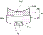
For example, as shown in fig. 3, a pad 30 for a tilting pad bearing 10 according to one embodiment includes: a first member 32 having a bearing surface 30A, and a second member 34 provided on the back side of the first member 32.
In several embodiments, the bearing shell 30 may be constructed as follows: a plurality of bearing rings 11 are provided on the inner peripheral side thereof at different positions in the rotation direction S of the rotor shaft 2, and support the rotor shaft 2 from below.
The bearing bush 30 has an outer peripheral surface facing the carrier ring 11, in addition to the bearing surface 30A as an inner peripheral surface facing the rotor shaft 2. The bearing surface 30A and the outer peripheral surface each have a shape curved so as to have a curvature corresponding to the rotor shaft 2 in the circumferential direction.
In some embodiments, at least one of the back surface of the first member 32 and the surface of the second member 34 facing the back surface of the first member 32 has a recess 60 for forming a cavity between the first member 32 and the second member 34. In some embodiments, for example, as shown in fig. 3, the concave portion 60 may be formed on the back surface of the first member 32, that is, on the surface of the first member 32 opposite to the bearing surface 30A and facing the second member 34.
When such a recess 60 is provided, a cavity is formed between the first member 32 and the second member 34, and when a load is applied to the bearing surface 30A, a portion of the first member 32 adjacent to the cavity can be deformed in a manner of being deflected toward the second member 34, that is, in a direction away from the rotor shaft 2. Therefore, the occurrence of a portion where the local surface pressure is higher than the surrounding area on the bearing surface 30A can be suppressed. Even when a portion having a high local surface pressure is generated in the bearing surface 30A of the first member 32, the peak value of the local surface pressure applied to the bearing surface 30A can be alleviated. Therefore, particularly at the time of low-speed rotation, it is possible to prevent the plastic flow from occurring in the bearing surface 30A for suppressing the temperature increase due to the friction between the rotor shaft 2 and the first member 32.
For example, as shown in fig. 4, in another example, the concave portion 60A may be formed on the surface of the second member 34, that is, the surface of the second member 34 that faces the first member 32. In addition, for example, as shown in fig. 5, in still another example, a concave portion 60 may be formed on the back surface of the first member 32, and a concave portion 60A may be formed on the surface of the second member 34. In the case of the configuration in which both the recess 60 and the recess 60A are provided, a stroke (relief stroke) for the first member 32 to be deflected in the direction away from the rotor shaft 2 can be secured to be large.
In several embodiments, the second member 34 may be configured to be tiltable with respect to the carrier ring 11. Thus, the bearing bush 30 including the second member 34 and the first member 32 is supported to be tiltable on the carrier ring 11. For example, the curvature of the back surface of the second member 34 corresponding to the outer peripheral surface of the shoe 30 may be larger than the curvature of the inner peripheral surface of the carrier ring 11 facing the back surface.
In some embodiments, the bearing bush 30 may further include a support member 70 provided on the back side of the second member 34 and supporting the first member 32 and the second member 34 to be tiltable. In this case, the contact between the second member 34 and the support member 70 may be such that either one of the facing surfaces is a curved surface and the other is a flat surface, or both of them may have curved surfaces that are convex toward each other. In addition, when the respective centers of curvature are located on the same side with respect to the contact portion, any one of the centers of curvature inscribed in the other may have a larger curvature than the other. Thus, the back surface of the second member 34 can be in tiltable contact with the support member 70.
In some embodiments, for example, as shown in fig. 3 to 5, the support member 70 may be disposed on the back side of the second member 34 and include a convex portion 74 formed to be convex toward the second member 34.
In several embodiments, the protrusion 74 may be configured to make point contact with the second member 34. In this case, the convex portion 74 may be a so-called spherical pivot whose surface facing the second member 34 is a spherical surface. In other embodiments, the projection 74 may be configured to be in line contact with the second member 34, or may be configured to be in surface contact with the second member 34, for example.
In some embodiments, a concave portion 34A may be formed on the back surface of the second member 34, that is, on the surface of the second member 34 facing the radially outer side of the carrier ring 11, and at least a part of the convex portion 74 may be accommodated in the concave portion 34A.
In several embodiments, the support member 70 may include a gasket 72 disposed between the boss 74 and the second member 34. The spacer 72 may be formed in a substantially flat plate shape, for example. In some embodiments, the pad 72 may be disposed so as to contact the bottom surface of the recess 34A, and the protrusion 74 may be disposed so as to support the first member 32 and the second member 34 via the pad 72 so as to be tiltable.
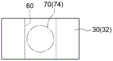
In some embodiments, the recess 60 may be formed in at least a part of the installation range of the support member 70 when the bearing bush 30 is viewed in a plan view. That is, the recess 60 may not be provided so as to cover the entire installation range of the support member 70 when the bearing bush 30 is viewed in plan view, and may be formed in a range smaller than the support member 70. In this case, the concave portion 60 may be formed in a range including a contact portion (contact point, contact line, or contact surface) between the convex portion 74 of the support member 70 and the second member 34 (or the spacer 72) as "at least a part of the installation range of the support member 70" when the bearing bush 30 is viewed in a plan view.
Specifically, as shown in fig. 6, when the convex portion 74 is, for example, a spherical pivot, the concave portion 60 may be formed in a range including at least a part of the installation range of the support member 70 (specifically, the convex portion 74) when the bearing bush 30 is viewed in plan.
Here, in the tiltable bush 30, a local surface pressure tends to be high in a portion on the bearing surface 30A whose back surface is supported by the support member 70. In this regard, as described above, according to the configuration in which the recess 60 is formed in at least a part of the installation range of the support member 70 when the bearing bush 30 is viewed in plan, at least a part of the portion of the first member 32 in which the surface pressure of the bearing surface 30A is likely to increase can be deflected in a direction away from the rotor shaft 2. Therefore, the surface pressure can be released, and the occurrence of a portion where the local surface pressure is higher than the surrounding portion on the bearing surface 30A can be prevented, or even if a portion where the local surface pressure is high is generated, the peak value of the surface pressure can be alleviated. Therefore, the surface pressure applied to the bearing surface 30A can be reduced, and the plastic flow can be prevented from occurring in the bearing surface 30A.
In one embodiment, the recess 60 may be formed over the entire installation range of the support member 70 when the bearing bush 30 is viewed in plan. For example, as shown in fig. 7, the concave portion 60 may be formed in a range equal to or larger than the installation range of the support member 70 including the entire installation range of the support member 70 (specifically, the convex portion 74) when the bearing bush 30 is viewed in a plan view.
According to the above configuration, the load applied between the bearing surface 30A and the support member 70 can be more reliably dispersed by the concave portion 60 formed over the entire installation range of the support member 70 when the bearing bush 30 is viewed in plan, and the occurrence of a portion where the local surface pressure is higher than the surrounding portion on the bearing surface 30A can be prevented.
In several embodiments, the hollow formed due to the recess 60 may communicate with the outer space of the bearing shell 30. For example, as shown in fig. 8, the recess 60 may be formed in a groove shape penetrating the bearing shell 30 in the axial direction of the rotor shaft 2. With this configuration, the lubricant can enter and exit between the inside and the outside of the cavity formed by the concave portion 60. Thus, for example, shaft vibration of the rotor shaft 2 input to the bearing 30 can provide the bearing 30 with a damping function.
In other embodiments, the recess 60 may be formed in a groove shape that penetrates the bearing bush 30 in a direction orthogonal to both the axial direction and the radial direction of the rotor shaft 2.
The communication portion (opening portion) between the pad 30 and the external space thereof can be arbitrarily set to an appropriate size in consideration of damping performance against axial vibration and the like.
In several embodiments, the first member 32 may be formed of copper, a copper alloy, or steel. Additionally, in several embodiments, the second member 34 may be formed of steel.
The first member 32 includes: a copper-based metal layer 32A formed of copper or a copper alloy; and a white alloy layer 32B formed on the inner circumferential surface side of the copper-based metal layer 32A (the inner side in the radial direction of the rotor shaft 2) and serving as the bearing surface 30A (see, for example, fig. 3 to 5). The second member 34 constitutes the steel layer of the bearing shell 30.
With this configuration, in addition to the fact that the recess 60 can suppress the occurrence of a portion where the local surface pressure is higher than the surrounding area on the bearing surface 30A, the first member 32 made of copper or a copper alloy can enhance heat dissipation to prevent thermal deformation of the bearing bush 30, and the second member 34 made of steel can suppress pressure deformation of the bearing bush 30. Therefore, it is possible to more reliably prevent the occurrence of a portion where the local surface pressure is higher than the surrounding area in the bearing surface 30A, or to alleviate the peak value even when a portion where the local surface pressure is higher than the surrounding area is generated, and therefore, it is possible to prevent the plastic flow of the bearing surface 30A. Further, since the heat radiation property is improved by using copper, the bearing load applied with the same oil film thickness can be increased at the time of high-speed rotation, and thus the tilting pad bearing 10 can be downsized.
According to the configurations of the above-disclosed embodiments, the rotary machine 1 having the structure in which the rotor shaft 2 is supported by the tilting pad bearing 10 capable of preventing the plastic flow of the bearing surface 30A can be obtained.
[ second embodiment ]
Next, a tilting pad bearing 110 of a second embodiment will be explained. The same components as those of the rotary machine 1 according to the above-described embodiments are denoted by the same reference numerals, and redundant description thereof is omitted.
Fig. 9 is a sectional view of the tilting pad bearing 110 of the second embodiment as viewed from a direction perpendicular to the axial direction. Fig. 10 is a sectional view of the tilting pad bearing 110 of the second embodiment as viewed from the axial direction.
As shown in fig. 9 and 10, the tilting pad bearing 110 applied to the rotary machine 100 in the second embodiment is different from the above-described embodiments in that the recess 60 is not provided. The tilting pad bearing 110 according to the second embodiment is a journal bearing that employs a direct lubrication system as a lubrication system.
The tilting pad bearing 110 includes: at least one bearing shell 130: and a carrier ring 11 provided on an outer peripheral side of the at least one bush 130 and configured to hold the at least one bush 130. The carrier ring 11 includes at least one (5 in the present embodiment) oil supply nozzle 25 to 29 for supplying lubricating oil to the bearing surface 130A.
For example, as shown in fig. 9 and 10, each of the bearing shoes 130 has a bearing surface 130A, and includes: a first member 132 formed of copper, a copper alloy, or steel, and a second member 134 provided on the back side of the first member 132 and formed of steel.
The first member 132 includes: a copper-based metal layer 132A formed of copper or a copper alloy; and a white alloy layer 132B formed on the inner circumferential surface side of the copper-based metal layer 132A (the inner side in the radial direction of the rotor shaft 2) and serving as the bearing surface 130A (see fig. 10). The second member 134 constitutes the steel layer of the bearing shell 130.
According to the above-described structure, the heat radiation property of the bearing bush 130 can be improved by the first member 132 formed of copper or a copper alloy to reduce thermal deformation, and the rigidity of the bearing bush 130 can be improved by the second member 134 made of steel to suppress pressure deformation. This can reduce the local surface pressure acting on the bearing surface 30A, and prevent plastic flow of the bearing surface 130A during low-speed rotation. Further, since the heat radiation performance is improved by the first member 132 made of copper or a copper alloy, the bearing load that can be applied with the same oil film thickness increases at high-speed rotation, and thus the tilting pad bearing 110 can be downsized.
The present invention is not limited to the above embodiments, and includes modifications of the above embodiments and combinations of the modifications and the embodiments as appropriate.
For example, the terms "in a certain direction", "along a certain direction", "parallel", "orthogonal", "central", "concentric" or "coaxial" and the like denote expressions of relative or absolute arrangement, and strictly speaking, not only such an arrangement, but also a state of relative displacement when there is a tolerance, an angle or a distance to the extent that the same function is obtained.
For example, "the same", "equal", and "homogeneous" indicate that the expression of the states in which the objects are equal, strictly speaking, indicates that the states are not only equal but also states in which a tolerance or a difference in degree of obtaining the same function is present.
For example, the expression indicating the shape such as a square shape or a cylindrical shape indicates not only the shape such as a square shape or a cylindrical shape in a strict geometrical sense but also a shape including a concave and convex portion, a chamfered portion, and the like in a range in which the same effect is obtained.
On the other hand, expressions such as "having", "including", or "having" one constituent element are not exclusive expressions that exclude the presence of other constituent elements.
Description of reference numerals:
1. 100 rotating machine
2 rotor shaft
3 bearing housing
4 upper half bearing shell
5 lower half bearing shell
10. 110 tilting pad bearing
11 bearing ring
12 upper half bearing ring
13 lower half bearing ring
17. 18 side plate
17A, 18A holes
20. 21 guide metal
25-29 oil supply nozzle
30. 130 bearing shell
30A, 130A bearing surface
32. 132 first member
32A copper-based metal layer
32B white alloy layer
34, 134 second member
34A recess
40 upper side wedge
41 upper side shim
50 lower side wedge
51 lower side shim
60 concave part
70 support member
72 liner
74 convex portion.
Claims (8)
1. A bearing bush for a tilting pad bearing,
the bearing pad for the tilting pad bearing comprises:
a first member having a bearing surface; and
a second member provided on a back surface side of the first member,
it is characterized in that the preparation method is characterized in that,
at least one of a back surface of the first member and a front surface of the second member facing the back surface of the first member has a recess for forming a cavity between the first member and the second member,
the first member is formed of copper or a copper alloy,
the second member is formed of steel,
the cavity is not communicated with the outer space of the bearing bush.
2. A bearing bush for a tilting pad bearing,
the bearing pad for the tilting pad bearing comprises:
a first member having a bearing surface; and
a second member provided on a back surface side of the first member,
it is characterized in that the preparation method is characterized in that,
at least one of a back surface of the first member and a front surface of the second member facing the back surface of the first member has a recess for forming a cavity between the first member and the second member,
the first member is formed of copper or a copper alloy,
the second member is formed of steel,
the recess is a groove that penetrates the bearing shell in an axial direction of the rotor shaft facing the bearing surface, and the hollow communicates with an external space of the bearing shell via an opening of the groove in the bearing shell.
3. Bearing pad for a tilting pad bearing according to claim 1 or 2,
the pad for a tilting pad bearing further includes a support member provided on a back surface side of the second member and supporting the first member and the second member to be tiltable,
the recess is formed in at least a part of an installation range of the support member when the bearing shell is viewed in plan.
4. Bearing pad for a tilting pad bearing according to claim 3,
the recess is formed over the entire installation range of the support member when the bearing shell is viewed in plan.
5. Bearing pad for a tilting pad bearing according to claim 1 or 2,
the tilting pad bearing includes a direct lubrication type bearing including a nozzle for supplying a lubricating oil to the bearing surface.
6. A tilting pad bearing, characterized in that,
the tilting pad bearing includes:
at least one bearing shell according to any one of claims 1 to 5; and
and a carrier ring provided on an outer peripheral side of at least one of the bearing pads and configured to hold the at least one of the bearing pads.
7. A tilting pad bearing, characterized in that,
the tilting pad bearing includes:
at least one bearing shell according to any one of claims 1 to 5; and
a carrier ring provided on an outer peripheral side of at least one of the bearing shoes and configured to hold the at least one of the bearing shoes,
the carrier ring comprises at least one oil supply nozzle for supplying lubricating oil to the bearing surface.
8. A rotary machine, characterized in that,
the rotating machine is provided with:
the tilting pad bearing of claim 6 or 7; and
and a rotor shaft rotatably supported by the tilt pad bearing.
Applications Claiming Priority (3)
| Application Number | Priority Date | Filing Date | Title |
|---|---|---|---|
| JP2017-058334 | 2017-03-24 | ||
| JP2017058334A JP6899235B2 (en) | 2017-03-24 | 2017-03-24 | Bearing pads for tilting pad bearings, tilting pad bearings and rotating machinery |
| PCT/JP2018/003378 WO2018173502A1 (en) | 2017-03-24 | 2018-02-01 | Bearing pad for tilting pad bearing, tilting pad bearing, and rotary machine |
Publications (2)
| Publication Number | Publication Date |
|---|---|
| CN110462229A CN110462229A (en) | 2019-11-15 |
| CN110462229B true CN110462229B (en) | 2021-03-02 |
Family
ID=63586072
Family Applications (1)
| Application Number | Title | Priority Date | Filing Date |
|---|---|---|---|
| CN201880019122.1A Active CN110462229B (en) | 2017-03-24 | 2018-02-01 | Bearing bush for tilting pad bearing, and rotary machine |
Country Status (5)
| Country | Link |
|---|---|
| US (1) | US11193528B2 (en) |
| JP (1) | JP6899235B2 (en) |
| CN (1) | CN110462229B (en) |
| DE (1) | DE112018001578T5 (en) |
| WO (1) | WO2018173502A1 (en) |
Families Citing this family (4)
| Publication number | Priority date | Publication date | Assignee | Title |
|---|---|---|---|---|
| JP6979332B2 (en) * | 2017-10-31 | 2021-12-15 | 三菱パワー株式会社 | Tilting pad bearing |
| CN110242666B (en) * | 2019-06-14 | 2024-01-12 | 中国船舶重工集团公司第七0三研究所 | Self-positioning tilting pad bearing structure of ocean mobile nuclear turbine |
| CN110443000B (en) * | 2019-08-13 | 2023-04-25 | 哈尔滨理工大学 | Oil film thickness calculation method for oil pad tilting type double-rectangular-cavity static pressure thrust bearing |
| DE102021124856A1 (en) | 2021-09-27 | 2023-03-30 | Voith Patent Gmbh | Tilting Pad Radial Bearing and Shaft Assembly |
Citations (8)
| Publication number | Priority date | Publication date | Assignee | Title |
|---|---|---|---|---|
| GB1304800A (en) * | 1970-11-12 | 1973-01-31 | ||
| JPS5830523A (en) * | 1981-08-18 | 1983-02-23 | Ebara Corp | Inclined pad type vibration suppressing bearing |
| US4765759A (en) * | 1987-06-15 | 1988-08-23 | Westinghouse Electric Corp. | Journal bearing support and alignment device |
| CN1216509A (en) * | 1996-04-18 | 1999-05-12 | 杜兰玛克斯股份有限公司 | Grooved staved bearing assembly |
| CN101761546A (en) * | 2009-11-04 | 2010-06-30 | 西安交通大学 | Combined radial sliding bearing with tilting pad and fixed pad |
| CN104533955A (en) * | 2015-01-13 | 2015-04-22 | 江南大学 | Water lubrication tilting pad static-pressure bearing structure cooled through water returning grooves |
| CN105443429A (en) * | 2014-08-06 | 2016-03-30 | 沈阳透平机械股份有限公司 | Compact non-backing plate double oil-film damp bearing and manufacturing method thereof |
| JP2016142313A (en) * | 2015-01-30 | 2016-08-08 | 三菱日立パワーシステムズ株式会社 | Tilting pad bearing and rotary machine |
Family Cites Families (26)
| Publication number | Priority date | Publication date | Assignee | Title |
|---|---|---|---|---|
| JPS4425364Y1 (en) * | 1965-12-22 | 1969-10-24 | ||
| JPS4917717Y1 (en) * | 1970-12-19 | 1974-05-09 | ||
| JPS5121058B2 (en) | 1972-04-28 | 1976-06-30 | ||
| JPS5334725B2 (en) | 1972-06-07 | 1978-09-22 | ||
| JPS589525A (en) | 1981-07-10 | 1983-01-19 | 株式会社日立製作所 | Dc power source device |
| JPS589525U (en) * | 1981-07-13 | 1983-01-21 | 石川島播磨重工業株式会社 | bearing |
| JPS59147114A (en) * | 1983-02-14 | 1984-08-23 | Fuji Electric Co Ltd | Two-layer type thrust bearing pad |
| JPS59180116A (en) * | 1983-03-28 | 1984-10-13 | Mitsubishi Heavy Ind Ltd | Pad type bearing device |
| JPS6037698A (en) | 1983-08-09 | 1985-02-27 | 株式会社三陽電機製作所 | Device for firing discharge tube |
| JPS6037698U (en) * | 1983-08-22 | 1985-03-15 | 富士電機株式会社 | Thrust bearing device for vertical shaft rotating machine |
| US4533262A (en) * | 1983-09-21 | 1985-08-06 | General Electric Company | Trimetallic bearings |
| JPS6088119A (en) | 1983-10-13 | 1985-05-17 | Toray Ind Inc | Yarn for polyester fiber like animal hair and its preparation |
| JPS6088119U (en) * | 1983-11-24 | 1985-06-17 | 三菱重工業株式会社 | pad type bearing |
| CH668811A5 (en) * | 1984-07-19 | 1989-01-31 | Glyco Metall Werke | HYDRODYNAMIC SLIDING BEARING. |
| US4686403A (en) * | 1986-11-07 | 1987-08-11 | Westinghouse Electric Corp. | Dynamoelectric machine with rockable bearing supports |
| JPH07293554A (en) * | 1994-04-21 | 1995-11-07 | Mitsubishi Heavy Ind Ltd | Tilting pad type bearing device |
| JPH10288220A (en) * | 1997-04-14 | 1998-10-27 | Ebara Corp | Tilting pad bearing |
| JP2001124062A (en) | 1999-10-21 | 2001-05-08 | Hitachi Ltd | Tilting pad bearing device |
| JP2001165152A (en) | 1999-12-10 | 2001-06-19 | Mitsubishi Heavy Ind Ltd | Bearing device |
| WO2005122684A2 (en) * | 2004-06-15 | 2005-12-29 | Aly El-Shafei | Methods of controlling the instability in fluid film bearings |
| JP4764486B2 (en) | 2009-02-27 | 2011-09-07 | 三菱重工業株式会社 | Journal bearing |
| CN203035746U (en) * | 2012-04-02 | 2013-07-03 | 珠海格力电器股份有限公司 | Dynamic pressure bearing, high-speed fluid power machinery, high-speed centrifugal compressor |
| JP6045813B2 (en) | 2012-05-11 | 2016-12-14 | 株式会社東芝 | Tilting pad journal bearing |
| CN203130803U (en) * | 2012-11-22 | 2013-08-14 | 烟台大丰轴瓦有限责任公司 | Novel bearing bush |
| CN103967934A (en) * | 2014-05-17 | 2014-08-06 | 浙江正盛轴瓦有限责任公司 | Vibration isolating bearing |
| CN104613094B (en) * | 2015-01-30 | 2017-04-05 | 江苏科技大学 | A kind of MULTILAYER COMPOSITE bearing shell sliding bearing with oiling chamber |
-
2017
- 2017-03-24 JP JP2017058334A patent/JP6899235B2/en active Active
-
2018
- 2018-02-01 CN CN201880019122.1A patent/CN110462229B/en active Active
- 2018-02-01 WO PCT/JP2018/003378 patent/WO2018173502A1/en active Application Filing
- 2018-02-01 DE DE112018001578.5T patent/DE112018001578T5/en active Pending
- 2018-02-01 US US16/494,434 patent/US11193528B2/en active Active
Patent Citations (8)
| Publication number | Priority date | Publication date | Assignee | Title |
|---|---|---|---|---|
| GB1304800A (en) * | 1970-11-12 | 1973-01-31 | ||
| JPS5830523A (en) * | 1981-08-18 | 1983-02-23 | Ebara Corp | Inclined pad type vibration suppressing bearing |
| US4765759A (en) * | 1987-06-15 | 1988-08-23 | Westinghouse Electric Corp. | Journal bearing support and alignment device |
| CN1216509A (en) * | 1996-04-18 | 1999-05-12 | 杜兰玛克斯股份有限公司 | Grooved staved bearing assembly |
| CN101761546A (en) * | 2009-11-04 | 2010-06-30 | 西安交通大学 | Combined radial sliding bearing with tilting pad and fixed pad |
| CN105443429A (en) * | 2014-08-06 | 2016-03-30 | 沈阳透平机械股份有限公司 | Compact non-backing plate double oil-film damp bearing and manufacturing method thereof |
| CN104533955A (en) * | 2015-01-13 | 2015-04-22 | 江南大学 | Water lubrication tilting pad static-pressure bearing structure cooled through water returning grooves |
| JP2016142313A (en) * | 2015-01-30 | 2016-08-08 | 三菱日立パワーシステムズ株式会社 | Tilting pad bearing and rotary machine |
Also Published As
| Publication number | Publication date |
|---|---|
| JP6899235B2 (en) | 2021-07-07 |
| WO2018173502A1 (en) | 2018-09-27 |
| JP2018159462A (en) | 2018-10-11 |
| CN110462229A (en) | 2019-11-15 |
| DE112018001578T5 (en) | 2019-12-19 |
| US20200392986A1 (en) | 2020-12-17 |
| US11193528B2 (en) | 2021-12-07 |
Similar Documents
| Publication | Publication Date | Title |
|---|---|---|
| CN110462229B (en) | Bearing bush for tilting pad bearing, and rotary machine | |
| KR101748762B1 (en) | Half thrust bearing and bearing device using the same | |
| JP4554583B2 (en) | Thrust bearing device | |
| US9909615B2 (en) | Thrust bearing and bearing device for crankshaft of internal combustion engine | |
| EP2850327B1 (en) | Journal oil bearing | |
| US9909614B2 (en) | Bearing device for crankshaft of internal combustion engine | |
| US10006490B2 (en) | Half thrust bearing and bearing device using the same | |
| JP2008095723A (en) | Rolling bearing | |
| KR20190077237A (en) | Half thrust bearing | |
| CN111201381B (en) | Tilting pad bearing | |
| KR102240987B1 (en) | Bearing device and rotating machine | |
| JP5922808B1 (en) | Bearing device and method for installing bearing device | |
| KR102371208B1 (en) | Tilting pad bearing using multiple support methods | |
| JP6403593B2 (en) | Journal bearing and rotating machine | |
| US20230258224A1 (en) | Half thrust bearing | |
| KR100799546B1 (en) | A tilting pad radial journal bearing which the hardness and cooling efficiency are improved | |
| JP7239508B2 (en) | bearing | |
| JP2019124234A (en) | Main bearing for crank shaft of internal combustion engine | |
| JP2017172723A (en) | Slide bearing | |
| US20220316523A1 (en) | Fluid film bearing | |
| KR102115855B1 (en) | Journal bearing and rolling machine | |
| JP2019124233A (en) | Connecting rod bearing for crank shaft of internal combustion engine | |
| JP2019183957A (en) | Self-aligning bearing | |
| JP2019120283A (en) | Vehicle power transmission device | |
| JP2017180676A (en) | Foil bearing |
Legal Events
| Date | Code | Title | Description |
|---|---|---|---|
| PB01 | Publication | ||
| PB01 | Publication | ||
| SE01 | Entry into force of request for substantive examination | ||
| SE01 | Entry into force of request for substantive examination | ||
| GR01 | Patent grant | ||
| GR01 | Patent grant | ||
| TR01 | Transfer of patent right | ||
| TR01 | Transfer of patent right |
Effective date of registration: 20210716 Address after: Kanagawa Prefecture, Japan Patentee after: Mitsubishi Power Co., Ltd Address before: Tokyo, Japan Patentee before: MITSUBISHI HEAVY INDUSTRIES, Ltd. |