CN110448382B - Indicator mechanism for actuator controlled surgical instrument - Google Patents
Indicator mechanism for actuator controlled surgical instrument Download PDFInfo
- Publication number
- CN110448382B CN110448382B CN201910766785.6A CN201910766785A CN110448382B CN 110448382 B CN110448382 B CN 110448382B CN 201910766785 A CN201910766785 A CN 201910766785A CN 110448382 B CN110448382 B CN 110448382B
- Authority
- CN
- China
- Prior art keywords
- surgical instrument
- cylinder
- region
- indicator
- aperture
- Prior art date
- Legal status (The legal status is an assumption and is not a legal conclusion. Google has not performed a legal analysis and makes no representation as to the accuracy of the status listed.)
- Active
Links
Images


Classifications
-
- A—HUMAN NECESSITIES
- A61—MEDICAL OR VETERINARY SCIENCE; HYGIENE
- A61B—DIAGNOSIS; SURGERY; IDENTIFICATION
- A61B90/00—Instruments, implements or accessories specially adapted for surgery or diagnosis and not covered by any of the groups A61B1/00 - A61B50/00, e.g. for luxation treatment or for protecting wound edges
- A61B90/08—Accessories or related features not otherwise provided for
-
- A—HUMAN NECESSITIES
- A61—MEDICAL OR VETERINARY SCIENCE; HYGIENE
- A61B—DIAGNOSIS; SURGERY; IDENTIFICATION
- A61B34/00—Computer-aided surgery; Manipulators or robots specially adapted for use in surgery
- A61B34/30—Surgical robots
-
- A—HUMAN NECESSITIES
- A61—MEDICAL OR VETERINARY SCIENCE; HYGIENE
- A61B—DIAGNOSIS; SURGERY; IDENTIFICATION
- A61B34/00—Computer-aided surgery; Manipulators or robots specially adapted for use in surgery
- A61B34/30—Surgical robots
- A61B34/37—Master-slave robots
-
- A—HUMAN NECESSITIES
- A61—MEDICAL OR VETERINARY SCIENCE; HYGIENE
- A61B—DIAGNOSIS; SURGERY; IDENTIFICATION
- A61B17/00—Surgical instruments, devices or methods, e.g. tourniquets
- A61B2017/00477—Coupling
-
- A—HUMAN NECESSITIES
- A61—MEDICAL OR VETERINARY SCIENCE; HYGIENE
- A61B—DIAGNOSIS; SURGERY; IDENTIFICATION
- A61B90/00—Instruments, implements or accessories specially adapted for surgery or diagnosis and not covered by any of the groups A61B1/00 - A61B50/00, e.g. for luxation treatment or for protecting wound edges
- A61B90/08—Accessories or related features not otherwise provided for
- A61B2090/0803—Counting the number of times an instrument is used
-
- A—HUMAN NECESSITIES
- A61—MEDICAL OR VETERINARY SCIENCE; HYGIENE
- A61B—DIAGNOSIS; SURGERY; IDENTIFICATION
- A61B90/00—Instruments, implements or accessories specially adapted for surgery or diagnosis and not covered by any of the groups A61B1/00 - A61B50/00, e.g. for luxation treatment or for protecting wound edges
- A61B90/08—Accessories or related features not otherwise provided for
- A61B2090/0807—Indication means
Abstract
The present invention relates to an indicator mechanism for an actuator controlled surgical instrument. An indicator mechanism for a surgical instrument includes an aperture secured to a base. The indicator body is rotatably supported by the base. The indicator body includes features for engaging a motor that rotates the indicator body. A visual indicator visible through the aperture is coupled to the indicator body. The detent mechanism holds the indicator body in one of two positions. A first of the two positions provides a visual indication that the surgical instrument is working, and a second of the two positions provides a visual indication that the surgical instrument is expired. The controller may track usage events of the surgical instrument to determine expiration. The use event may include operations and conditions other than those occurring in the surgical instrument. When the usage event tracked by the controller indicates expiration, the controller may rotate the motor to set the visual indication to expiration.
Description
The present invention is a divisional application of chinese patent application No.201580012933.5(PCT/US2015/020870) entitled "indicator mechanism for actuator controlled surgical instrument" filed on date 2015, 3, 17.
Cross Reference to Related Applications
This application relates to and claims priority from U.S. provisional application No. 61/954,453 entitled "apparatus machinery FOR a server operated minor heated" filed on day 3, month 17 2014 and U.S. provisional application No. 62/012,018 entitled "apparatus machinery FOR AN operated minor heated" filed on day 6, month 13 2014, each of which is incorporated herein by reference in its entirety FOR all purposes.
Technical Field
Embodiments of the invention relate to the field of indicators; and more particularly to displaying a non-resettable indicator for at least one of two states of an actuator controlled surgical instrument.
Background
Minimally Invasive Surgery (MIS) (e.g., endoscopy, laparoscopy, thoracoscopy, cystoscopy, etc.) allows a patient to be operated through a small incision using elongated surgical instruments that are introduced to an internal surgical site. Typically, a cannula is inserted through the incision to provide an access port for the surgical instrument. The surgical site typically includes a body cavity, such as the abdominal cavity of a patient. The body cavity may optionally be inflated with a transparent fluid such as insufflation gas. In conventional minimally invasive surgery, a surgeon manipulates tissue by using a manual end effector of an elongated surgical instrument while viewing the surgical site on a video monitor.
The elongated surgical instrument will typically have an end effector in the form of a surgical tool (such as forceps, scissors, clips, needle holders, etc.) at one end of the elongated tube. Surgical instruments are typically coupled to the elongate tube by one or more articulation sections to control the position and/or orientation of the surgical instrument. An actuator that provides an actuation force to control the articulation section is coupled to the other end of the elongate tube. A device coupling the actuator force to the articulation section extends through the elongated tube. Two actuators may be provided for controlling two articulation sections, such as an "arm" that positions the surgical tool and a "wrist" that orients and manipulates the surgical tool, wherein a means for coupling the two actuator forces extends through the elongated tube.
It may be desirable for the elongate tube to be flexible to some extent to allow the surgical instrument to adapt to the geometry of the surgical access path. In some cases, the articulation section provides access to a surgical site that is not directly in line with the surgical access port. Because of the flexibility provided by the cable and because of the cable's ability to transmit large forces, large distances through small cross-sections, it may be desirable to use the cable as a means of coupling the actuator force to the articulation section.
The cables may operate close to their maximum allowable load to minimise the cross-section of the cables and hence the elongate tubes. For this and other reasons, the number of uses of this type of surgical instrument may be limited.
In view of the foregoing, it would be desirable to provide an indicator that can indicate that a surgical instrument has expired and should be removed from inventory.
Disclosure of Invention
An indicator mechanism for a surgical instrument includes an aperture secured to a base. The indicator body is rotatably supported by the base. The indicator body includes features for engaging a motor that rotates the indicator body. A visual indicator visible through the aperture is coupled to the indicator body. The detent mechanism holds the indicator body in one of two positions. A first of the two positions provides a visual indication that the surgical instrument is working, and a second of the two positions provides a visual indication that the surgical instrument is expired. The controller may track usage events of the surgical instrument to determine expiration. The use event may include operations and conditions other than those occurring in the surgical instrument. When the usage event tracked by the controller indicates expiration, the controller may rotate the motor to set the visual indication to expiration.
Other features and advantages of the present invention will be apparent from the accompanying drawings and from the detailed description that follows.
Drawings
The invention may best be understood by referring to the following description and accompanying drawings that are used to illustrate embodiments of the invention by way of example and not by way of limitation. In the drawings, wherein like reference numerals refer to like elements:
fig. 1 is a simplified perspective view of a teleoperated surgical system having an actuator-controlled surgical instrument inserted through a port in a patient's abdominal cavity.
FIG. 2 is a plan view of a surgical instrument for use with the actuator.
Fig. 3 is a detailed view of the proximal control mechanism 240 of the surgical instrument shown in fig. 2.
Fig. 4 is a view of the proximal control mechanism shown in fig. 3 with the housing removed.
Fig. 5 is a perspective view of the proximal control mechanism shown in fig. 4.
Fig. 6 is an exploded view of the proximal control mechanism.
FIG. 7 is a plan view of the indicator mechanism in the first operating position.
FIG. 8 is a plan view of the indicator mechanism in a second operating position.
FIG. 9 is a plan view of the indicator mechanism as it transitions between the first and second operating positions.
FIG. 10 is a cross-sectional view of the cylinder taken along line 10-10 in FIG. 7.
FIG. 11 is a perspective view of the key shaft and disk.
FIG. 12 is a perspective view of another keyed shaft and disk.
FIG. 13 is a perspective view of yet another keyed shaft and disk.
Fig. 14A and 14B are perspective views of two sides of another embodiment of an indicator mechanism.
Fig. 15 is a block diagram illustrating a control system that may be used with a surgical instrument that includes a mechanism for displaying a visual indication of the expiration of the surgical instrument.
Fig. 16 is a flow chart of a method that may be performed by the controller for providing a visual indication of whether the surgical instrument 1530 is expired.
Detailed Description
In the following description, numerous specific details are set forth. However, it is understood that embodiments of the invention may be practiced without these specific details. In other instances, well-known circuits, structures and techniques have not been shown in detail in order not to obscure the understanding of this description.
In the following description, reference is made to the accompanying drawings that show several embodiments of the invention. It is to be understood that other embodiments may be utilized, and that mechanical composition, structural, electrical, and operational changes may be made without departing from the spirit and scope of the present disclosure. The following detailed description is not to be taken in a limiting sense, and the scope of embodiments of the present invention is defined only by the claims of the issued patent.
The terminology used herein is for the purpose of describing particular embodiments only and is not intended to be limiting of the invention. Spatially relative terms, such as "below," "lower," "above," "upper," and the like, may be used for convenience in describing a relationship of one element or feature to another element or feature illustrated in the figures. It will be understood that the spatially relative terms are intended to encompass different orientations of the device in use or operation in addition to the orientation depicted in the figures. For example, if the device in the figures is turned over, elements described as "below" or "beneath" other elements or features would then be oriented "above" the other elements or features. Thus, the exemplary term "below" can encompass both an orientation of above and below. The device may be otherwise oriented (e.g., rotated 90 or at other orientations) and the spatially relative descriptors used herein interpreted accordingly.
As used herein, the singular forms "a", "an" and "the" are intended to include the plural forms as well, unless the context indicates otherwise. It will be further understood that the terms "comprises" and/or "comprising" specify the presence of stated features, steps, operations, elements, and/or components, but do not preclude the presence or addition of one or more other features, steps, operations, elements, components, and/or groups thereof.
Fig. 1 is a view of an illustrative bedside portion 100 of a teleoperated surgical system, according to an embodiment of the present invention. The bedside portion 100 includes support assemblies 110 and one or more surgical instrument manipulators 112 at the end of each support assembly. The support assembly optionally includes one or more unpowered, lockable mating joints for positioning the surgical instrument manipulator 112 relative to the surgical patient. As depicted, the bedside 100 rests on the floor. In other embodiments, the bedside portion may be mounted to a wall, a ceiling, an operating table 126 that also supports the patient's body 122, or other operating room equipment. Further, although the bedside portion 100 is shown to include four manipulators 112, more or fewer manipulators 112 may be used. Still further, the bedside portion 100 may be comprised of a single component as shown, or it may comprise two or more separate components, each optionally mounted in various possible ways.
Each surgical instrument manipulator 112 supports one or more surgical instruments 120 that operate at a surgical site within a patient's body 122. Each manipulator 112 may be provided in various forms that allow the associated surgical instrument to move in one or more mechanical degrees of freedom (e.g., all six cartesian degrees of freedom, five or fewer cartesian degrees of freedom, etc.). Typically, mechanical or control constraints limit each manipulator 112 to moving its associated surgical instrument about a center of motion on the instrument that remains stationary relative to the patient, and this center of motion is typically located where the instrument enters the body.
The term "surgical instrument" is used herein to describe a medical device configured to be inserted into the body of a patient and used to perform a surgical or diagnostic procedure. Surgical instruments typically include an end effector associated with one or more surgical tasks, such as forceps, needle holders, scissors, bipolar cauteries, tissue stabilizers or retractors, clip appliers, stapling devices, imaging devices (e.g., endoscopes or ultrasound probes), and so forth. Some surgical instruments used with embodiments of the present invention further provide an articulated support (sometimes referred to as a "wrist") for the end effector, enabling manipulation of the position and orientation of the end effector in one or more mechanical degrees of freedom relative to the instrument's shaft. Further, many surgical end effectors include functional mechanical degrees of freedom, such as jaws that open or close or a knife that translates along a path. The surgical instrument may also contain stored (e.g., on semiconductor memory within the instrument) information that may be permanent or may be updatable by the surgical system. Accordingly, the system may provide one-way or two-way communication of information between the instrument and one or more system components.
A functional teleoperated surgical system will typically include a vision system portion (not shown) that enables an operator to visually inspect the surgical site from the patient's body 122. The vision system generally includes a surgical instrument having a video image capture function 128 ("camera instrument") and one or more video displays for displaying captured images. In some surgical system configurations, the camera instrument 128 includes optics that transfer images from the distal end of the camera instrument 128 to one or more imaging sensors (e.g., CCD or CMOS sensors) outside the patient's body 122. Alternatively, an imaging sensor may be positioned at the distal end of the camera instrument 128, and the signals generated by the sensor may be transmitted along a lead or wirelessly for processing and display on a video display. An illustrative video display is a stereoscopic display on a surgeon console in a Surgical system sold by Intuitive Surgical corporation of senneville, california (incorporated.).
The functional teleoperated surgical system will further include a control system portion (not shown) for controlling movement of the surgical instrument 120 while the instrument is within the patient. The control system portion may be at a single location in the surgical system or it may be distributed at two or more locations in the system (e.g., the control system portion components may be in the bedside portion 100 of the system, in a dedicated system console, or in a separate equipment rack). Remote master/slave control may be accomplished in a variety of ways depending on the degree of control desired, the size of the surgical assembly being controlled, and other factors. In some embodiments, the control system portion includes one or more manually operated input devices, such as joysticks, exoskeleton gloves, power and gravity compensated manipulators, and the like. These input devices control a telemotor, which in turn controls the movement of the surgical instrument.
The force generated by the telemotor is transmitted via a drive train mechanism that transmits the force from the telemotor to the surgical instrument 120. In some telesurgical embodiments, the input devices controlling the manipulators may be located remotely from the patient, in or out of the room in which the patient is located. The input signal from the input device is then transmitted to the control system portion. Those familiar with telemanipulation, telecontrol, and telepresence surgery will appreciate such systems and their components, such as the da vinci (da) marketed by intuitive surgical companies ) Surgical systems and systems manufactured by Computer Motion, Inc
 Surgical systems and various illustrative components of such systems.
As shown, surgical instrument 120 and optional introducer 124 (e.g., a cannula in the patient's abdominal cavity) are removably coupled to the distal end of manipulator 112, with surgical instrument 120 being inserted through introducer 124. The teleoperated actuators in manipulator 112 move surgical instrument 120 as a whole. Manipulator 112 further includes instrument carriage 130. Surgical instrument 120 is removably coupled to carriage 130. The teleoperated actuators housed in the carriage 130 provide a variety of controller motions that the surgical instrument 120 translates into various movements of the end effector on the surgical instrument. Thus, the teleoperated actuators in the carriage 130 only move one or more components of the surgical instrument 120 and not the instrument as a whole. Inputs for controlling the instrument as a whole or components of the instrument are such that inputs provided by the surgeon to the control system portion (the "master" commands) are translated into corresponding actions of the surgical instrument (the "slave" responses).
Fig. 2 is a side view of an illustrative embodiment of surgical instrument 120 including a distal portion 250 and a proximal control mechanism 240 coupled by elongate tube 210. The distal end portion 250 of the surgical instrument 120 may provide any of a variety of end effectors, such as a forceps 254, a needle holder, a cautery device, a cutting tool, an imaging device (e.g., an endoscope or ultrasound probe), or a combination device including a combination of two or more of a variety of tools and imaging devices as shown. In the illustrated embodiment, the end effector 254 is coupled to the elongate tube 210 by a "wrist" 252 that allows the orientation of the end effector to be manipulated with reference to the instrument tube 210.
The teleoperated actuator controlled surgical instruments used in the present invention are controlled by a plurality of flexible cables. The cable provides a compact and flexible means for transmitting force to the joint. A typical elongated tube 210 for use in surgical instrument 120 is small, perhaps 6 millimeters in diameter, roughly the diameter of a large soda straw. The small scale of the mechanisms in the surgical instrument 120 results in unique mechanical conditions and problems for the construction of these mechanisms that are different from the conditions and problems that exist in similar mechanisms constructed on a larger scale because the forces and strengths of the materials are not scaled in the same ratio as the size of the mechanisms. The cables must fit within the elongated tube 210 and be able to bend as they pass through the joints 252, 254 offset from the surgical tool 262.
The cable is stranded/stranded to provide flexibility. They operate at high levels of stress and bending around small diameter pulleys. These conditions require that the actuator-controlled surgical instrument be deactivated/retracted after a certain number of uses. The actuator controlled surgical instrument is provided with a visual indicator 244 that can be set by the actuator when the surgical instrument reaches a rated number of uses. This alerts personnel that the surgical instrument may no longer be usable and therefore should not be cleaned and returned to inventory.
The surgical instrument may be identified by the surgical system and the use of the instrument may be tracked by the system. Visual indicators 244 may be set by the system to assist a person in handling the actuator-controlled surgical instrument. The visual indicator 244 settings may or may not be used by the system to determine whether an actuator-controlled surgical instrument is available. The surgical instrument may or may not track the number of times it has been used and autonomously set the visual indicator 244.
Fig. 3 is a detailed view of the proximal control mechanism 240 of the actuator-controlled surgical instrument shown in fig. 2. In this view, the visual indicator 244 can be more clearly seen. Shaded indications are shown to indicate an expiration indication, such as red, which is shown as a visual indication.
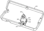
Fig. 4 is a view of the proximal control mechanism 240 shown in fig. 3 with the housing 300 removed to illustrate the indicator mechanism. The indicator may include a rotatable indicator body, such as rotatable cylinder 400, which may support an indicator arm 402. The indicator arm may provide an area visible through the aperture to provide a visual indicator 244. In other embodiments, the area visible through the aperture may be on the indicator body rather than on the indicator arm. The indicator arm is used if the distance between the axis of rotation of the indicator body and the aperture of the visual indicator 244 is such that using the indicator body alone may be too cumbersome.
FIG. 5 is a perspective view of the proximal control mechanism 240 shown in FIG. 4, wherein only the components of the indicator mechanism are shown. Fig. 6 is an exploded view of the proximal control mechanism 240 more clearly showing certain aspects of the indicator mechanism.
The rotatable cylinder 400 is supported by the base 242 of the proximal control mechanism. The keyed shaft 500 engages the cylinder 400 to rotate the cylinder. The drive disk 610 is disposed at the end of the keyed shaft 500 extending from the side of the base 242 opposite the side supporting the cylinder 400. The barrel is secured to keyed shaft 500 such that the barrel, shaft and drive disk provide a rotatable assembly on the base 242 of the proximal control mechanism.
The area visible through the aperture of the visual indicator 244 can be seen in fig. 6. The first region 600 provides a visual indication that the instrument is still working. The second region 602 provides a visual indication that the instrument has expired.
Fig. 7, 8 and 9 are plan views of the indicator mechanism in various operating positions. Fig. 7 shows cylinder 400 in a first position, in which first region 600 is aligned with the aperture of visual indicator 244 to provide a visual indication that the instrument is still working, i.e., the instrument can be reused for at least one more work cycle. Fig. 8 shows cylinder 400 in a second position, in which second region 602 is aligned with the aperture of visual indicator 244 to provide a visual indication that the instrument has expired, i.e., the instrument is not available for additional work cycles.
It is desirable that the cylinder 400 be maintained in either the first or second position such that the visual indicator 244 provides a clear indication of the condition of the surgical instrument. It is also desirable that the cylinder be securely held so that the visual indicator 244 does not move with handling, which may include vigorous cleaning activities. In some embodiments, the visual indicator may provide more than two positions, and in these embodiments it may be desirable to hold the cylinder in these additional positions.
To maintain the cylinder 400 in either the first or second position, the base 242 includes detents 506, 606 that engage projections 504, 704 on the lower periphery of the cylinder adjacent the base. As illustrated in fig. 9, the lower periphery of the cylinder is elastically deformed as the projections 504, 704 rotate past the stops 506, 606. The dashed reference circle 900 shows the undeformed profile of the cylinder. For simplicity, the entire cylinder has been shown as deformed. In practice, only the lower periphery of the cylinder will deform as shown.
While the stop mechanism has been shown as two interference protrusions, it should be understood that the stop mechanism may be provided in other forms. For example, the first portion of the stop mechanism, represented by rigid stops 506, 606 on the base 242, may be provided as a depression rather than a protrusion. Likewise, the second portion of the stop mechanism, represented by the resilient protrusions 504, 704 on the cylinder 400, may be provided as a depression rather than a protrusion. In other embodiments, the first portion of the stop mechanism supported by the base 242 may be resilient while the portion supported by the cylinder 400 is rigid. In other embodiments, the stop mechanism may provide more than two holding positions.
Fig. 10 is a cross-sectional view of the cylinder 400 taken along line 10-10 in fig. 7. This shows a skirt portion 902 of the cylinder 400 which provides a thin section adjacent the lower periphery of the cylinder which is resiliently deformable to allow the projections 504, 704 to rotate past the stops 506, 606. As shown, the skirt portion 902 is slightly higher than the ledge 604 because the upper edge of the full thickness portion of the skirt portion adjacent the barrel is relatively inelastic. The thickness and height of the skirt portion 902 may be selected to provide a desired resistance to moving the cylinder from the first position to the second position.
It may be noted that the projections 504, 704 have angled edges that abut the stops 506, 606 when the cylinder 400 is in the first position and square edges that abut the stops when the cylinder is in the second position. Thus, the protrusion provides a ratchet that allows the cylinder to rotate from the first position to the second position and resists rotation from the second position to the first position.
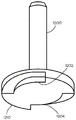
Fig. 11 is a perspective view of a keyed shaft 1100 and a disk 1110 that may be used to rotate the barrel 400 of the indicator mechanism. The puck 1110 can include recesses 1102, 1104 that engage corresponding projections that are driven by a motor to rotate the cylinder from a first position to a second position to indicate that the instrument has expired.
Fig. 12 is a perspective view of another keyed shaft 1200 and disk 1210 that may be used to rotate the cylinder 400 of the indicator mechanism. The disc 1210 may include recesses 1202, 1204 that engage corresponding projections that are driven by a motor to rotate the cylinder from the first position to the second position to indicate that the instrument has expired. In the present embodiment, one side of each recess is provided with a ramp portion. This configuration allows the spring-loaded protrusion to reliably engage the right-angled side of the recess so that the motor can strike the right-angled side with some momentum to provide the force necessary to elastically deform the cylinder 400. The motor may slowly engage the right angle side with low force to establish the position of the right angle side and then prepare a known amount before striking the right angle side at high speed. In another embodiment, the motor controller knows the position of the motor and the right angle side. The motor controller may position the motor to place the engagement protrusion away from the right-angle side based on the known position.
Fig. 13 is a perspective view of yet another keyed shaft 1300 and disk 1310 that may be used to rotate the barrel 400 of the indicator mechanism. The present embodiment provides a ramp recess 1302, 1304 similar to that shown in figure 12. However, the recesses are at different distances from the axis of rotation of the shaft 1300 and cylinder 400. This allows the protrusion to rotate almost a full revolution before striking the right angled side of the recess, which may allow more force to be transferred to rotate the cylinder from the first position to the second position to indicate that the instrument has expired.
It will be appreciated that the spline shaft and disc may provide protrusions that engage corresponding recesses driven by the motor, and the recesses may have a profile similar to that shown for the disc portion of the spline shaft.
Fig. 14A and 14B show perspective views of two sides of another embodiment of an indicator mechanism. This embodiment provides an indicator body in the form of a disk 1410 and an indicator arm 1404 in one piece. The puck includes features for engaging a motor that rotates the puck, such as a ramp having right angled sides 1412, 1414. The indicator arm extends from the periphery of the disc parallel to the axis of rotation of the disc.
A shaft 1500 extends from the disk 1410. The shaft is inserted into an opening 612 seen in fig. 6. The hook feature 1502 engages a surface of the base 242 of the proximal control mechanism on the side furthest from the disc. The protrusion 1504 on the shaft 1500 engages the detents 506, 606 on the base 242 and operates as previously described.
An additional opening is provided in the base 242 of the proximal control mechanism to allow the indicator arm 1404 to extend into the interior of the proximal control mechanism. This allows the end of the indicator arm furthest from the disk to be seen through the aperture of the visual indicator 244. The indicator arm end may be decorated with two visually distinct areas 1400, 1402 to provide a visual indication of whether the instrument has expired.
In another embodiment, the indicator arm is visible through an aperture of the visual indicator 244 in one state (such as while the instrument is still in operation). In the second state (such as when the instrument has expired), the indicator arm cannot be visible through the aperture of the visual indicator 244. In the second state, a visual feature on the base that is blocked by the indicator arm in the first state becomes visible to provide a visual indication of the second state.
Fig. 15 is a block diagram illustrating a control system that may be used with a surgical instrument 1530 that includes a mechanism for displaying a visual indication of the expiration of the surgical instrument, as described above, the surgical instrument 1530 may be coupled to an instrument carriage 1520 that provides mechanical and/or electrical inputs 1522 that actuate and control the surgical instrument. The controller 1510 may provide inputs 1512 (typically electrical inputs) to the instrument carriage 1520 to control operation of the instrument carriage.
The surgical instrument 1530 may provide a mechanical and/or electrical output 1534 for indicating a condition at the surgical instrument. The instrument carriage 1520 may provide an output 1524 (typically an electrical output) to indicate the condition at the instrument carriage and/or by an output 1534 from the surgical instrument. The controller 1510 may provide an output 1514 to the user 1500 to provide indications of various conditions of the surgical instrument 1530 and/or the surgical system.
Fig. 16 is a flow chart of a method that may be performed by the controller 1510 for providing a visual indication of whether the surgical instrument 1530 is expired. The surgical instrument 1530 includes any of the types of indicator mechanisms described above. The surgical instrument 1530 also includes a mechanism (such as an RFID tag) 1600 that allows the controller 1510 to identify the particular surgical instrument installed. Identification of the surgical instrument 1530 allows the controller to maintain a history of use of the particular surgical instrument and identify the type and amount of use that caused the surgical instrument to expire.
The controller determines if a usage event has occurred 1610 — yes. While the flow diagram shows the detection of usage events 1610 as a polling loop, it should be understood that the occurrence of usage events may be used to direct the method without polling.
Some surgical instruments may expire after being used for a predetermined number of surgical procedures. For such surgical instruments, the use event may be the installation of the surgical instrument. The use event may be the installation of the surgical instrument a predetermined length of time since the previous installation of the surgical instrument, since the surgical instrument may be removed and reinstalled during a single surgical procedure. The use event may also be the installation of the surgical instrument after a system power cycle has occurred since the previous installation of the surgical instrument.
Other surgical instruments may expire after a predetermined number of actuations of the surgical instrument. For example, a surgical stapler may allow a predetermined number of firings. Surgical shears may allow for a predetermined number of closures. For these surgical instruments, the controller will identify the appropriate actuation of the surgical instrument as a use event.
When a usage event occurs 1610 — yes, the controller 1510 will adjust the usage count 1620 for the particular surgical device 1530 that has been identified as being installed 1600. The controller 1510 then compares the usage count to a predetermined expiration count to determine whether the particular surgical instrument 1530 has expired 1630. It is to be understood that the controller may accumulate the usage count and compare it to a predetermined expiration count, or it may set the usage count to a predetermined expiration count and decrement the usage count such that a zero value of the usage count indicates that the particular surgical instrument 1530 has expired 1630.
When the controller 1510 determines 1630 that a particular surgical instrument 1530 has expired, the controller provides an output 1512 to an instrument carriage 1520 that activates a motor to rotate an indicator body in the surgical instrument from a first position to a second position to provide a visual indication on the surgical instrument that the surgical instrument has expired. The controller 1510 may issue a command to the instrument carriage 1520 to rotate the motor in a manner that allows the motor to gain momentum prior to rotating the indicator body. This may enable the motor to overcome the resistance of the mechanism provided to prevent accidental rotation of the indicator body.
It should be understood that other criteria besides those described as examples may be used to identify usage events. In some cases, the use event makes it impossible for a mechanism that is fully housed in the surgical instrument to determine when the surgical instrument has expired. The methods described herein of providing a visual indication of whether a surgical instrument is expired allow for other system conditions and events to be considered to determine when a surgical instrument is expired.
While certain exemplary embodiments have been described and shown in the accompanying drawings, it is to be understood that such embodiments are merely illustrative of and not restrictive on the broad invention, and that this invention not be limited to the specific constructions and arrangements shown and described, since various other modifications may occur to those ordinarily skilled in the art. The description is thus to be regarded as illustrative instead of limiting.
Claims (13)
1. An indicator mechanism for a surgical instrument, the indicator mechanism comprising:
a base including an aperture;
a cylinder rotatably supported by the base;
a first region coupled to the cylinder, the first region indicating that the surgical instrument is still working when visible through the aperture;
a second region coupled to the cylinder, the second region indicating expiration of the surgical instrument when visible through the aperture;
a keyed shaft coupled to the cylinder, the keyed shaft including a drive disk on a side of the base opposite the cylinder to rotate the cylinder; and
a stop mechanism configured to hold the cylinder such that one of the first region or the second region is visible through the aperture from outside the surgical instrument.
2. The indicator mechanism of claim 1 wherein the detent mechanism further comprises a resilient skirt portion coupled to the cylinder and a protrusion is coupled to the resilient skirt portion.
3. The indicator mechanism of claim 2 wherein the stop mechanism further comprises a portion fixed to the base that engages the protrusion.
4. The indicator mechanism of claim 1 wherein the stop mechanism comprises a ratchet that allows rotation of the barrel from a first position to a second position and resists rotation of the barrel from the second position to the first position.
5. The indicator mechanism of any one of claims 1-4, further comprising an indicator arm coupling the first region and the second region to the cylinder.
6. The indicator mechanism of any one of claims 1-4 wherein the drive disk comprises a ramp portion for engaging a motor.
7. The indicator mechanism of any one of claims 1-4 wherein the stop mechanism holds the cylinder so that just one of the first region or the second region is visible.
8. A method for providing a visual indication of whether a surgical instrument is expired, the method comprising:
providing a cylinder rotatably supported by a base of the surgical instrument, the base including an aperture;
providing a first region coupled to the cylinder, the first region indicating that the surgical instrument is still working when visible through the aperture;
providing a second region coupled to the cylinder, the second region indicating expiration of the surgical instrument when visible through the aperture;
rotating the cylinder with a drive disk on a side of the base opposite the cylinder, the drive disk coupled to the cylinder by a keyed shaft; and is
Holding the cylinder with a stop mechanism such that one of the first region or the second region is visible through the aperture from outside the surgical instrument.
9. The method of claim 8, further comprising:
determining whether a usage event has occurred;
in the event that the act of determining whether a usage event has occurred determines that a usage event has occurred, adjusting a count of usage events for the surgical instrument to produce an adjusted count of usage events;
determining whether the surgical instrument is expired based on the adjusted count of usage events; and is
Rotating the cylinder if the act of determining whether the surgical instrument is expired determines that the surgical instrument is expired.
10. The method of claim 9, wherein determining whether a usage event has occurred further comprises: determining whether a predetermined length of time has elapsed since the surgical instrument was previously actuated.
11. The method of claim 9, wherein determining whether a usage event has occurred further comprises: determining whether a system power cycle has occurred since the surgical instrument was previously actuated.
12. The method of claim 9, wherein determining whether a usage event has occurred further comprises: determining whether the surgical instrument has been actuated.
13. The method of any of claims 8-12, further comprising rotating a motor to gain momentum prior to rotating the cylinder.
Applications Claiming Priority (6)
| Application Number | Priority Date | Filing Date | Title |
|---|---|---|---|
| US201461954453P | 2014-03-17 | 2014-03-17 | |
| US61/954,453 | 2014-03-17 | ||
| US201462012081P | 2014-06-13 | 2014-06-13 | |
| US62/012,081 | 2014-06-13 | ||
| PCT/US2015/020870 WO2015142780A1 (en) | 2014-03-17 | 2015-03-17 | Indicator mechanism for an actuator controlled surgical instrument |
| CN201580012933.5A CN106102637B (en) | 2014-03-17 | 2015-03-17 | The indicator means of surgical operating instrument for actuator control |
Related Parent Applications (1)
| Application Number | Title | Priority Date | Filing Date |
|---|---|---|---|
| CN201580012933.5A Division CN106102637B (en) | 2014-03-17 | 2015-03-17 | The indicator means of surgical operating instrument for actuator control |
Publications (2)
| Publication Number | Publication Date |
|---|---|
| CN110448382A CN110448382A (en) | 2019-11-15 |
| CN110448382B true CN110448382B (en) | 2022-09-27 |
Family
ID=54145186
Family Applications (2)
| Application Number | Title | Priority Date | Filing Date |
|---|---|---|---|
| CN201910766785.6A Active CN110448382B (en) | 2014-03-17 | 2015-03-17 | Indicator mechanism for actuator controlled surgical instrument |
| CN201580012933.5A Active CN106102637B (en) | 2014-03-17 | 2015-03-17 | The indicator means of surgical operating instrument for actuator control |
Family Applications After (1)
| Application Number | Title | Priority Date | Filing Date |
|---|---|---|---|
| CN201580012933.5A Active CN106102637B (en) | 2014-03-17 | 2015-03-17 | The indicator means of surgical operating instrument for actuator control |
Country Status (6)
| Country | Link |
|---|---|
| US (3) | US10470829B2 (en) |
| EP (2) | EP3119330B1 (en) |
| JP (3) | JP6869723B2 (en) |
| KR (2) | KR20160135222A (en) |
| CN (2) | CN110448382B (en) |
| WO (1) | WO2015142780A1 (en) |
Families Citing this family (5)
| Publication number | Priority date | Publication date | Assignee | Title |
|---|---|---|---|---|
| CN110448382B (en) * | 2014-03-17 | 2022-09-27 | 直观外科手术操作公司 | Indicator mechanism for actuator controlled surgical instrument |
| EP3538010A4 (en) * | 2016-11-11 | 2020-07-22 | Intuitive Surgical Operations Inc. | Teleoperated surgical system with surgical instrument wear tracking |
| KR20230163594A (en) * | 2017-08-10 | 2023-11-30 | 인튜어티브 서지컬 오퍼레이션즈 인코포레이티드 | Increased usable instrument life in telesurgical systems |
| EP4125698A1 (en) | 2020-04-02 | 2023-02-08 | Intuitive Surgical Operations, Inc. | Devices for instrument use recording, devices for recording instrument reprocessing events, and related systems and methods |
| CN114176668B (en) * | 2021-12-31 | 2023-08-22 | 佗道医疗科技有限公司 | Indication mechanism for use condition of surgical instrument, use method and anti-counterfeiting method for surgical instrument |
Citations (2)
| Publication number | Priority date | Publication date | Assignee | Title |
|---|---|---|---|---|
| WO2008067143A2 (en) * | 2006-11-30 | 2008-06-05 | Gregory Lee Heacock | Disposable ophthalmic/medical apparatus with timed color change indication |
| EP2484304A2 (en) * | 2011-02-03 | 2012-08-08 | Terumo Kabushiki Kaisha | Medical manipulator system |
Family Cites Families (53)
| Publication number | Priority date | Publication date | Assignee | Title |
|---|---|---|---|---|
| GB733148A (en) * | 1951-07-19 | 1955-07-06 | Arthur Rex Jackson | Improvements in charts or indicators |
| US4606343A (en) * | 1980-08-18 | 1986-08-19 | United States Surgical Corporation | Self-powered surgical fastening instrument |
| DE3204522A1 (en) * | 1982-02-10 | 1983-08-25 | B. Braun Melsungen Ag, 3508 Melsungen | SURGICAL SKIN CLIP DEVICE |
| US4619391A (en) * | 1984-04-18 | 1986-10-28 | Acme United Corporation | Surgical stapling instrument |
| US4951860A (en) * | 1987-12-28 | 1990-08-28 | Edward Weck & Co. | Method and apparatus for storing, dispensing and applying surgical staples |
| US5359993A (en) * | 1992-12-31 | 1994-11-01 | Symbiosis Corporation | Apparatus for counting the number of times a medical instrument has been used |
| US5279309A (en) * | 1991-06-13 | 1994-01-18 | International Business Machines Corporation | Signaling device and method for monitoring positions in a surgical operation |
| US5397046A (en) * | 1991-10-18 | 1995-03-14 | United States Surgical Corporation | Lockout mechanism for surgical apparatus |
| US5397323A (en) * | 1992-10-30 | 1995-03-14 | International Business Machines Corporation | Remote center-of-motion robot for surgery |
| US5313935A (en) | 1992-12-31 | 1994-05-24 | Symbiosis Corporation | Apparatus for counting the number of times a surgical instrument has been used |
| JPH08248838A (en) * | 1995-03-11 | 1996-09-27 | Ricoh Co Ltd | Image forming device |
| GB9518402D0 (en) * | 1995-09-08 | 1995-11-08 | Armstrong Projects Ltd | Improvements in or relating to a robotic apparatus |
| US6786896B1 (en) * | 1997-09-19 | 2004-09-07 | Massachusetts Institute Of Technology | Robotic apparatus |
| US6331181B1 (en) * | 1998-12-08 | 2001-12-18 | Intuitive Surgical, Inc. | Surgical robotic tools, data architecture, and use |
| SE9702679D0 (en) * | 1997-07-11 | 1997-07-11 | Siemens Elema Ab | Device for calculating the number of uses of a sensor |
| US6468265B1 (en) * | 1998-11-20 | 2002-10-22 | Intuitive Surgical, Inc. | Performing cardiac surgery without cardioplegia |
| US10285694B2 (en) * | 2001-10-20 | 2019-05-14 | Covidien Lp | Surgical stapler with timer and feedback display |
| US6601748B1 (en) * | 2001-12-15 | 2003-08-05 | Modern Medical Equip. Mfg., Ltd. | Surgical stapler |
| AU2003207811A1 (en) * | 2002-02-15 | 2003-09-09 | The John Hopkins University | System and method for laser based computed tomography and magnetic resonance registration |
| US7621273B2 (en) * | 2003-10-28 | 2009-11-24 | Trudell Medical International | Indicating device with warning dosage indicator |
| JP2006081687A (en) * | 2004-09-15 | 2006-03-30 | Max Co Ltd | Medical stapler |
| JP4708830B2 (en) * | 2005-04-06 | 2011-06-22 | キヤノン株式会社 | Unit and image forming apparatus |
| EP3738521B1 (en) * | 2005-06-03 | 2023-10-18 | Covidien LP | Surgical stapler with timer and feedback display |
| KR101298492B1 (en) * | 2005-06-30 | 2013-08-21 | 인튜어티브 서지컬 인코포레이티드 | Indicator for tool state and communication in multiarm robotic telesurgery |
| US8241271B2 (en) * | 2005-06-30 | 2012-08-14 | Intuitive Surgical Operations, Inc. | Robotic surgical instruments with a fluid flow control system for irrigation, aspiration, and blowing |
| US7741802B2 (en) * | 2005-12-20 | 2010-06-22 | Intuitive Surgical Operations, Inc. | Medical robotic system with programmably controlled constraints on error dynamics |
| US7835823B2 (en) * | 2006-01-05 | 2010-11-16 | Intuitive Surgical Operations, Inc. | Method for tracking and reporting usage events to determine when preventive maintenance is due for a medical robotic system |
| US8708213B2 (en) * | 2006-01-31 | 2014-04-29 | Ethicon Endo-Surgery, Inc. | Surgical instrument having a feedback system |
| JP5085996B2 (en) * | 2006-10-25 | 2012-11-28 | テルモ株式会社 | Manipulator system |
| US7882509B2 (en) * | 2007-06-29 | 2011-02-01 | Emulex Design & Manufacturing Corporation | Expander-based solution to the dynamic STP address problem |
| US7739978B2 (en) * | 2007-09-18 | 2010-06-22 | Metso Automation Usa Inc. | Rotatable shaft position indicator |
| US7658162B2 (en) * | 2008-01-15 | 2010-02-09 | Ace Venture, Inc. | Self adhesive medication reminder device |
| CN201281819Y (en) * | 2008-09-12 | 2009-07-29 | Abb技术公司 | Teaching unit suitable for operation of robot unit |
| US8939894B2 (en) * | 2009-03-31 | 2015-01-27 | Intuitive Surgical Operations, Inc. | Three-dimensional target devices, assemblies and methods for calibrating an endoscopic camera |
| US9186136B2 (en) * | 2009-12-09 | 2015-11-17 | Covidien Lp | Surgical clip applier |
| US20120006252A1 (en) * | 2010-01-04 | 2012-01-12 | Kam Eileen Warner | Indicator |
| JP2013517068A (en) * | 2010-01-14 | 2013-05-16 | ザ リージェンツ オブ ザ ユニバーシティ オブ カリフォルニア | Apparatus, system and method for robotic microsurgery |
| EP2408174A1 (en) * | 2010-07-14 | 2012-01-18 | Deutsche Telekom AG | Messaging activity feed |
| JP5734631B2 (en) * | 2010-12-02 | 2015-06-17 | オリンパス株式会社 | Surgery support system |
| JP5830258B2 (en) * | 2011-03-17 | 2015-12-09 | オリンパス株式会社 | Surgery support system and surgical tool |
| US20130253480A1 (en) * | 2012-03-22 | 2013-09-26 | Cory G. Kimball | Surgical instrument usage data management |
| US9364278B2 (en) * | 2012-04-30 | 2016-06-14 | Covidien Lp | Limited reuse ablation needles and ablation devices for use therewith |
| CA2875594C (en) * | 2012-06-05 | 2019-09-24 | Optimized Ortho Pty Ltd | A method, guide, guide indicia generation means, computer readable storage medium, reference marker and impactor for aligning an implant |
| KR20140090374A (en) * | 2013-01-08 | 2014-07-17 | 삼성전자주식회사 | Single port surgical robot and control method thereof |
| US9782198B2 (en) * | 2013-03-28 | 2017-10-10 | Koninklijke Philips N.V. | Localization of robotic remote center of motion point using custom trocar |
| US9398935B2 (en) * | 2013-08-22 | 2016-07-26 | The Board Of Trustees Of The Leland Stanford Junior University | Robotic imaging system |
| CN105979902A (en) * | 2014-02-04 | 2016-09-28 | 皇家飞利浦有限公司 | Remote center of motion definition using light sources for robot systems |
| WO2015121765A1 (en) * | 2014-02-12 | 2015-08-20 | Koninklijke Philips N.V. | Robotic control of surgical instrument visibility |
| KR102237597B1 (en) * | 2014-02-18 | 2021-04-07 | 삼성전자주식회사 | Master device for surgical robot and control method thereof |
| CN110448382B (en) * | 2014-03-17 | 2022-09-27 | 直观外科手术操作公司 | Indicator mechanism for actuator controlled surgical instrument |
| US20150338728A1 (en) * | 2014-05-23 | 2015-11-26 | Thought Development, Inc. | System and method for continuously projecting a reference aid at an activity site |
| EP3169491A2 (en) * | 2014-07-15 | 2017-05-24 | Koninklijke Philips N.V. | Reconfigurable robot architecture for minimally invasive procedures |
| EP4125698A1 (en) * | 2020-04-02 | 2023-02-08 | Intuitive Surgical Operations, Inc. | Devices for instrument use recording, devices for recording instrument reprocessing events, and related systems and methods |
-
2015
- 2015-03-17 CN CN201910766785.6A patent/CN110448382B/en active Active
- 2015-03-17 CN CN201580012933.5A patent/CN106102637B/en active Active
- 2015-03-17 US US15/121,366 patent/US10470829B2/en active Active
- 2015-03-17 WO PCT/US2015/020870 patent/WO2015142780A1/en active Application Filing
- 2015-03-17 JP JP2016557995A patent/JP6869723B2/en active Active
- 2015-03-17 EP EP15765163.9A patent/EP3119330B1/en active Active
- 2015-03-17 EP EP19212146.5A patent/EP3632364B1/en active Active
- 2015-03-17 KR KR1020167026690A patent/KR20160135222A/en not_active IP Right Cessation
- 2015-03-17 KR KR1020227027793A patent/KR102560873B1/en active IP Right Grant
-
2019
- 2019-11-08 JP JP2019202823A patent/JP7000399B2/en active Active
- 2019-11-11 US US16/680,194 patent/US11344378B2/en active Active
-
2021
- 2021-09-24 JP JP2021155928A patent/JP7296435B2/en active Active
-
2022
- 2022-04-22 US US17/726,773 patent/US20220354598A1/en active Pending
Patent Citations (2)
| Publication number | Priority date | Publication date | Assignee | Title |
|---|---|---|---|---|
| WO2008067143A2 (en) * | 2006-11-30 | 2008-06-05 | Gregory Lee Heacock | Disposable ophthalmic/medical apparatus with timed color change indication |
| EP2484304A2 (en) * | 2011-02-03 | 2012-08-08 | Terumo Kabushiki Kaisha | Medical manipulator system |
Also Published As
| Publication number | Publication date |
|---|---|
| JP6869723B2 (en) | 2021-05-12 |
| EP3632364B1 (en) | 2021-09-01 |
| US11344378B2 (en) | 2022-05-31 |
| US20220354598A1 (en) | 2022-11-10 |
| CN110448382A (en) | 2019-11-15 |
| EP3119330A4 (en) | 2017-11-08 |
| JP2022002723A (en) | 2022-01-11 |
| US20160361048A1 (en) | 2016-12-15 |
| CN106102637B (en) | 2019-09-13 |
| JP2017512558A (en) | 2017-05-25 |
| KR20220119174A (en) | 2022-08-26 |
| JP7000399B2 (en) | 2022-01-19 |
| CN106102637A (en) | 2016-11-09 |
| WO2015142780A1 (en) | 2015-09-24 |
| EP3632364A1 (en) | 2020-04-08 |
| EP3119330A1 (en) | 2017-01-25 |
| KR20160135222A (en) | 2016-11-25 |
| US10470829B2 (en) | 2019-11-12 |
| JP2020018929A (en) | 2020-02-06 |
| KR102560873B1 (en) | 2023-07-31 |
| EP3119330B1 (en) | 2020-05-06 |
| US20200078107A1 (en) | 2020-03-12 |
| JP7296435B2 (en) | 2023-06-22 |
Similar Documents
| Publication | Publication Date | Title |
|---|---|---|
| US11259883B2 (en) | Robotics tool exchange | |
| JP7296435B2 (en) | Display mechanism for actuator controlled surgical instruments | |
| JP7240454B2 (en) | A coupler that transfers motion from a teleoperated actuator to a surgical instrument | |
| US20190216554A1 (en) | Sterile adapter assembly for a robotic surgical system | |
| CN113271884A (en) | System and method for integrating motion with an imaging device | |
| US20220117680A1 (en) | System and method for automated docking |
Legal Events
| Date | Code | Title | Description |
|---|---|---|---|
| PB01 | Publication | ||
| PB01 | Publication | ||
| SE01 | Entry into force of request for substantive examination | ||
| SE01 | Entry into force of request for substantive examination | ||
| GR01 | Patent grant | ||
| GR01 | Patent grant |