CN110410648B - Laser range finder support - Google Patents
Laser range finder support Download PDFInfo
- Publication number
- CN110410648B CN110410648B CN201910630866.3A CN201910630866A CN110410648B CN 110410648 B CN110410648 B CN 110410648B CN 201910630866 A CN201910630866 A CN 201910630866A CN 110410648 B CN110410648 B CN 110410648B
- Authority
- CN
- China
- Prior art keywords
- horizontal
- range finder
- pointer
- laser range
- vertical
- Prior art date
- Legal status (The legal status is an assumption and is not a legal conclusion. Google has not performed a legal analysis and makes no representation as to the accuracy of the status listed.)
- Active
Links
Images


Classifications
-
- F—MECHANICAL ENGINEERING; LIGHTING; HEATING; WEAPONS; BLASTING
- F16—ENGINEERING ELEMENTS AND UNITS; GENERAL MEASURES FOR PRODUCING AND MAINTAINING EFFECTIVE FUNCTIONING OF MACHINES OR INSTALLATIONS; THERMAL INSULATION IN GENERAL
- F16M—FRAMES, CASINGS OR BEDS OF ENGINES, MACHINES OR APPARATUS, NOT SPECIFIC TO ENGINES, MACHINES OR APPARATUS PROVIDED FOR ELSEWHERE; STANDS; SUPPORTS
- F16M11/00—Stands or trestles as supports for apparatus or articles placed thereon Stands for scientific apparatus such as gravitational force meters
- F16M11/20—Undercarriages with or without wheels
- F16M11/24—Undercarriages with or without wheels changeable in height or length of legs, also for transport only, e.g. by means of tubes screwed into each other
- F16M11/26—Undercarriages with or without wheels changeable in height or length of legs, also for transport only, e.g. by means of tubes screwed into each other by telescoping, with or without folding
- F16M11/32—Undercarriages for supports with three or more telescoping legs
-
- F—MECHANICAL ENGINEERING; LIGHTING; HEATING; WEAPONS; BLASTING
- F16—ENGINEERING ELEMENTS AND UNITS; GENERAL MEASURES FOR PRODUCING AND MAINTAINING EFFECTIVE FUNCTIONING OF MACHINES OR INSTALLATIONS; THERMAL INSULATION IN GENERAL
- F16M—FRAMES, CASINGS OR BEDS OF ENGINES, MACHINES OR APPARATUS, NOT SPECIFIC TO ENGINES, MACHINES OR APPARATUS PROVIDED FOR ELSEWHERE; STANDS; SUPPORTS
- F16M11/00—Stands or trestles as supports for apparatus or articles placed thereon Stands for scientific apparatus such as gravitational force meters
- F16M11/20—Undercarriages with or without wheels
- F16M11/24—Undercarriages with or without wheels changeable in height or length of legs, also for transport only, e.g. by means of tubes screwed into each other
- F16M11/38—Undercarriages with or without wheels changeable in height or length of legs, also for transport only, e.g. by means of tubes screwed into each other by folding, e.g. pivoting or scissors tong mechanisms
-
- G—PHYSICS
- G01—MEASURING; TESTING
- G01C—MEASURING DISTANCES, LEVELS OR BEARINGS; SURVEYING; NAVIGATION; GYROSCOPIC INSTRUMENTS; PHOTOGRAMMETRY OR VIDEOGRAMMETRY
- G01C1/00—Measuring angles
-
- G—PHYSICS
- G01—MEASURING; TESTING
- G01S—RADIO DIRECTION-FINDING; RADIO NAVIGATION; DETERMINING DISTANCE OR VELOCITY BY USE OF RADIO WAVES; LOCATING OR PRESENCE-DETECTING BY USE OF THE REFLECTION OR RERADIATION OF RADIO WAVES; ANALOGOUS ARRANGEMENTS USING OTHER WAVES
- G01S7/00—Details of systems according to groups G01S13/00, G01S15/00, G01S17/00
- G01S7/48—Details of systems according to groups G01S13/00, G01S15/00, G01S17/00 of systems according to group G01S17/00
- G01S7/481—Constructional features, e.g. arrangements of optical elements
Abstract
The invention provides a laser range finder support which comprises a triangular support body and an indicating disc assembly, wherein the indicating disc assembly comprises a horizontal indicating disc assembly and a vertical indicating disc assembly; the vertical indicating disc assembly comprises a vertical indicating disc, and angle scales, a second pointer and a laser range finder clamping seat are arranged on the vertical indicating disc; the orthographic projection of the vertical indicating dial on the horizontal indicating dial is superposed with the extension line of the orthographic projection of the first pointer on the horizontal indicating dial, and through holes are formed in the horizontal indicating dial and the horizontal supporting plate. The laser range finder support provided by the invention provides positioning capability in the horizontal direction and the vertical direction for the laser range finder, and improves the measurement precision of the laser range finder.
Description
Technical Field
The invention belongs to the technical field of architectural measurement, and particularly relates to a support for supporting a laser range finder.
Background
A portable laser rangefinder is a distance measuring instrument that is typically used in hand-held for rapid distance measurement. However, since it is difficult to precisely control the orientation during the handheld use, a certain measurement error may be caused.
For example, when the height is measured, the laser range finder is ensured to keep the vertical direction, so that the measured height is the actual height, and in the actual operation, the laser range finder is difficult to be completely vertical by hand-held operation; when horizontal distance measurement is carried out, the laser distance measuring instrument is horizontal and cannot have directional deviation, and the direction is difficult to accurately position due to hand holding.
Disclosure of Invention
The invention mainly solves the problem that the existing laser range finder is difficult to accurately position the measuring direction, so that the measurement is inaccurate, and provides a laser range finder support for improving the measuring accuracy of the laser range finder.
In order to solve the technical problems, the invention adopts the following technical scheme: a laser range finder support comprises a triangular support body and an indicating disc assembly, wherein a horizontal supporting plate is arranged at the top end of the triangular support body, the indicating disc assembly is arranged on the horizontal supporting plate and is positioned above the horizontal supporting plate, and the indicating disc assembly comprises a horizontal indicating disc assembly and a vertical indicating disc assembly;
the horizontal indicating disc assembly comprises a horizontal base plate and a horizontal indicating disc arranged on the horizontal base plate, the horizontal base plate is arranged on the horizontal supporting plate through a plurality of leveling knobs distributed along the circumference, leveling bubbles are arranged on the horizontal base plate, the horizontal indicating disc can horizontally rotate around a vertical shaft, and a first pointer pointing to a horizontal plane is fixedly arranged on the horizontal indicating disc;
the vertical indicating disc assembly comprises an installation plate fixedly arranged on the horizontal indicating disc and a vertical indicating disc fixedly arranged on the installation plate, and angle scales with zero scale marks and horizontal are uniformly distributed on the vertical indicating disc and are provided with a second pointer and a laser range finder clamping seat used for positioning a laser range finder; the pointing direction of the second pointer is parallel to the vertical disc surface of the vertical indicating disc, the second pointer can be shifted and rotated around the center of the vertical indicating disc and can be positioned at any position, and the laser range finder clamping seat and the second pointer are fixedly connected into a whole; the orthographic projection of the vertical indicating dial on the horizontal indicating dial is superposed with the extension line of the orthographic projection of the first pointer on the horizontal indicating dial;
the horizontal indicating disc and the horizontal supporting plate are provided with through holes for the laser of the laser range finder to penetrate downwards.
The laser range finder clamping seat comprises a shell and an adjusting mechanism used for adjusting the laser range finder to enable the laser transmission direction of the laser range finder to be parallel to and consistent with the direction of the second pointer, the adjusting mechanism comprises a first positioning plate and a second positioning plate which are positioned in the shell, the first positioning plate is movably connected to one side plate of the shell through at least two springs, the second positioning plate is connected to the other side plate of the shell through an adjusting bolt, and the first positioning plate and the second positioning plate enclose a clamping groove used for clamping the laser range finder;
be equipped with folding centering pointer on the second pointer, the centering pointer can with vertical dial is perpendicular and with folding switching between the parallel two kinds of states of vertical dial, work as the centering pointer fold to with when vertical dial is parallel, the direction of centering pointer with the direction of second pointer is unanimous, works as the centering pointer fold to with vertical dial is perpendicular just the laser projection that laser range finder sent is in when the center of centering pointer, laser range finder's laser transmission direction with the direction of second pointer is parallel and unanimous.
The horizontal base plate is also provided with a compass and a horizontal indicating ring, the horizontal indicating ring is concentric with the horizontal indicating disc and is positioned on the periphery of the horizontal indicating disc, and the horizontal indicating ring can horizontally rotate around a vertical shaft; the horizontal base plate is uniformly provided with outer ring angle scales positioned on the periphery of the horizontal indicating ring, the horizontal indicating ring is uniformly provided with inner ring angle scales positioned on the periphery of the horizontal indicating disc and outer ring azimuth marks positioned on the periphery of the inner ring angle scales, and the scale distribution of the outer ring angle scales is consistent with that of the compass.
The level bubble is located within the compass.
The triangular support main body can be telescopically lifted and can be folded.
The center of vertical dial has set firmly the center pin, the free end of center pin is equipped with spacing arch, the pot head of second pointer is established on the center pin just still the cover is equipped with on the center pin and is located spacing arch with compression spring between the second pointer and be located the second pointer with elastic friction disc between the vertical dial, the laser range finder cassette links firmly on this end of second pointer.
Compared with the prior art, the laser range finder support has the advantages that the indicating disc assembly is arranged, so that the laser range finder is positioned on the laser range finder clamping seat on the vertical indicating disc when the laser range finder support is used, the laser range finder is guaranteed to be vertical, the height measurement is convenient, and the laser range finder clamping seat can rotate along with the second pointer on the vertical indicating disc so as to realize the direction adjustment of the laser range finder on the vertical surface; meanwhile, the vertical indicating disc is fixedly arranged on the horizontal indicating disc, the direction of the laser range finder on the horizontal plane can be adjusted along with the rotation of the horizontal indicating disc, when the horizontal distance is measured, the laser range finder is arranged at the zero scale position of the vertical indicating disc, and then the horizontal indicating disc is rotated to enable the laser range finder to be aligned to a target to be measured; the laser range finder support provided by the invention provides positioning capability in the horizontal direction and the vertical direction for the laser range finder, and improves the measurement precision of the laser range finder.
Drawings
FIG. 1 is a schematic perspective view of a laser range finder bracket according to the present invention;
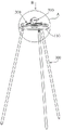
FIG. 2 is an enlarged view of portion A of FIG. 1;
FIG. 3 is a view from the direction B of FIG. 1;
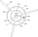
FIG. 4 is a detailed view of the horizontal indicator panel assembly of the laser rangefinder mount of the present invention;
FIG. 5 is an enlarged view of section C of FIG. 4;
FIG. 6 is a cross-sectional view taken along line D-D of FIG. 4;
FIG. 7 is a detailed structural view of a vertical indicator panel assembly of the laser rangefinder mount of the present invention;
FIG. 8 is a first schematic view of a mounting structure of a laser range finder clamping seat and a second pointer on a longitudinal indicating disc of the laser range finder bracket according to the present invention;
FIG. 9 is a second schematic view of a mounting structure of a laser range finder clamping seat and a second pointer on a longitudinal indicating disc of the laser range finder bracket according to the present invention;
fig. 10 is a schematic measurement diagram corresponding to an embodiment of the laser range finder bracket positioning laser range finder of the present invention for vertical distance measurement.
Detailed Description
In order to make the objects, technical solutions and advantages of the embodiments of the present invention clearer, the technical solutions in the embodiments of the present invention will be clearly and completely described below with reference to the drawings in the embodiments of the present invention, and it is obvious that the described embodiments are some, but not all, embodiments of the present invention. All other embodiments, which can be derived by a person skilled in the art from the embodiments given herein without making any creative effort, shall fall within the protection scope of the present invention.
Referring to fig. 1 to 3, a laser range finder support of the present embodiment for positioning a laser range finder when using the laser range finder comprises a tripod body 100 and an indicator panel assembly, wherein a horizontally arranged horizontal support plate 110 is arranged at the top end of the tripod body 100 as a support body of the whole indicator panel assembly, the indicator panel assembly is arranged on the horizontal support plate 110 and is located above the horizontal support plate 110, and the indicator panel assembly comprises a horizontal indicator panel assembly 200 and a vertical indicator panel assembly 300;
referring to fig. 4 to 6, in combination with fig. 1 to 3, the horizontal indicator panel assembly 200 includes a horizontal base panel 210 horizontally disposed and a horizontal indicator panel 220 disposed on the horizontal base panel 210, the horizontal base panel 210 is mounted on the horizontal support panel 110 by a plurality of leveling knobs 500 circumferentially arranged, a leveling bubble 241 is disposed on the horizontal base panel 210 to indicate whether the horizontal base panel 210 is leveled, after the horizontal base panel 210 is leveled, the panel surface of the horizontal indicator panel 220 is ensured to be horizontal, the horizontal indicator panel 220 can horizontally rotate around a vertical axis and is fixedly provided with a first pointer 230, and the first pointer 230 points to be parallel to the horizontal plane; for the rotation of the horizontal indicating dial 220 on the horizontal base plate 210, as shown in fig. 6, a T-shaped guide slot 290 is arranged on the horizontal base plate 210, the horizontal indicating dial 220 is adapted to be placed in the guide slot, and the rotation is achieved by manual poking;
meanwhile, referring to fig. 7 to 9, in conjunction with fig. 1 to 3, the vertical dial assembly 300 includes a mounting plate 310 fixedly mounted on the horizontal dial 220 and a vertical dial 320 fixedly mounted on the mounting plate 310; the dial face of the vertical indicating dial 320 is vertical, angle scales 321 with horizontal zero scale lines are uniformly distributed on the vertical indicating dial 320, a second pointer 330 and a laser range finder clamping seat 340 for positioning a laser range finder are arranged on the vertical indicating dial 320, the angle scales 321 are uniformly distributed on the circumference, the scale range is from-90 degrees to 90 degrees, namely the elevation angle range is 0-90 degrees, the depression angle is 0-90 degrees, the minimum scale value is 1 degree, the zero scale line and the 180 degree scale line are horizontal, and the 90 degree scale line and the-90 degree scale line are vertical; the second pointer 330 points parallel to the vertical dial surface of the vertical dial 320 and is used for indicating the angle scale 321 on the vertical dial 320, the second pointer 330 can be manually turned around the center of the vertical dial 320 and can be positioned at any position, and in particular, the second pointer 330 can be positioned at any indicating position by overcoming the gravity thereof through the friction force between the second pointer and the vertical dial 320; the laser range finder clamping seat 340 is fixedly connected with the second pointer 330 into a whole so as to adjust the orientation of the laser range finder in the clamping seat along with the rotation of the second pointer 330; in addition, the orthographic projection of the vertical indicating dial 320 on the horizontal indicating dial 220 coincides with the extension line of the orthographic projection of the first pointer 230 on the horizontal indicating dial 220, so that the rotation reference of the vertical indicating dial 320 and the rotation reference of the first pointer 230 are consistent, and the horizontal position pointed by the first pointer 230 is the horizontal position pointed by the vertical indicating dial 320 and further the horizontal position pointed by the laser range finder.
More specifically, as shown in fig. 9, a central shaft (not shown in the view angle reason figure) is fixedly disposed at the center of the vertical indicating disc 320, a limiting protrusion 360 is disposed at a free end of the central shaft, one end of the second pointer 330 (the end is an end opposite to the indicating end of the second pointer 330) is sleeved on the central shaft, and the laser distance meter holder 340 is fixedly connected to the end of the second pointer 330. The limiting protrusion 360 has an axial stopping function on the second pointer 330 to prevent the second pointer 330 from being separated from the vertical indicating disc 320, and a compression spring (not shown in the view angle reason figure) positioned between the limiting protrusion 360 and the second pointer 330 and an elastic friction plate 370 positioned between the second pointer 330 and the vertical indicating disc 320 are further sleeved on the central shaft to increase the friction force between the second pointer 330 and the vertical indicating disc 320 to overcome the gravity thereof so that the second pointer can be positioned at any indicating position, but the friction force is also ensured to be capable of being shifted when the second pointer 330 is shifted by hand.
Since the laser range finder is vertically downward when pointing at a depression angle of-90 °, in order not to affect smooth transmission and measurement of the laser, the horizontal indicating plate 220 and the horizontal supporting plate 110 are provided with through holes T for the laser of the laser range finder to pass through and transmit downward, as shown in fig. 1 to 3.
Since the laser distance measuring instrument support of the present embodiment is not necessarily completely horizontal, the horizontal support plate 110 is not necessarily completely horizontal, and the horizontal base plate 210 is not necessarily horizontal, before the measurement, the leveling knob 500 is used to adjust the horizontal base plate 210 to make the bubble of the bubble 241 located at the center of the bubble 241, so that the horizontal base plate 210 is leveled. According to the laser range finder support, the indicating disc assembly is arranged, and the laser range finder is positioned on the laser range finder clamping seat on the vertical indicating disc during use, so that the laser range finder is ensured to be vertical, the height measurement is convenient, and the laser range finder clamping seat can rotate along with the second pointer on the vertical indicating disc so as to realize the direction adjustment of the laser range finder on the vertical surface; meanwhile, the vertical indicating disc is fixedly arranged on the horizontal indicating disc, the direction of the laser range finder on the horizontal plane can be adjusted along with the rotation of the horizontal indicating disc, when the horizontal distance is measured, the laser range finder can be ensured to be horizontal only by arranging the laser range finder at the zero scale position of the vertical indicating disc, and then the horizontal indicating disc is rotated to enable the laser range finder to be aligned to the target to be measured; this embodiment laser range finder support provides the location ability of horizontal direction and vertical direction to laser range finder, has improved laser range finder's measurement accuracy.
Further, as shown in fig. 7 to 9, for the laser range finder socket 340 for positioning the laser range finder, it includes a housing 341 and an adjusting mechanism for adjusting the laser range finder to make its laser transmission direction parallel to and consistent with the direction of the second pointer 330, the adjusting mechanism includes a first positioning plate 342 and a second positioning plate 343 located in the housing 341, the first positioning plate 342 is movably connected to one side plate of the housing 341 by at least two springs 344, the second positioning plate 343 is connected to the other side plate of the housing 341 opposite to each other by an adjusting bolt 345, so that the first positioning plate 342 and the second positioning plate 343 are oppositely arranged, and the first positioning plate 342 and the second positioning plate 343 enclose into a slot 346 for clamping the laser range finder. Specifically, as shown in fig. 8, when the laser range finder 400 is mounted in the slot 346, the second positioning plate 343 pushes the laser range finder 400 to slide by rotating the adjusting bolt 345, and the first positioning plate 342 compresses the spring 344, so that the position of the laser range finder 400 is adjusted until the laser transmission direction is parallel to and consistent with the direction of the second pointer 330, so that the direction pointed by the second pointer 330 is the direction pointed by the laser range finder 400 on the vertical plane.
In order to visually observe whether the laser range finder 400 is adjusted in place, in the embodiment, the foldable centering pointer 350 is arranged on the second pointer 330, the centering pointer 350 can be folded and switched between two states of being perpendicular to the vertical indicating disc 320 and being parallel to the vertical indicating disc 320, when the centering pointer 350 is folded to be parallel to the vertical indicating disc 320, the direction of the centering pointer 350 is consistent with the direction of the second pointer 330, and when the centering pointer 350 is folded to be perpendicular to the vertical indicating disc 320 and laser emitted by the laser range finder 400 is projected to the center of the centering pointer 350, the laser transmission direction of the laser range finder 400 is parallel to and consistent with the direction of the second pointer 330. When the laser emitted from the laser range finder 400 is just projected on the center of the centering pointer 350 by adjusting the adjusting bolt 345, the laser range finder 400 is centered with the centering pointer 350 at this time, and when the centering pointer 350 is folded to be parallel to the vertical indicating dial 320, the pointing direction of the centering pointer 350 is identical to the pointing direction of the second pointer 330, and then the laser transmission direction of the laser range finder 400 is parallel to and points in the same direction as the pointing direction of the second pointer 330 by using the centering pointer 350 as an intermediate reference at this time.
In the prior art, a field measurer needs to hold the laser range finder to reach one wall and then aim at the other wall to measure, but the field measurer can not approach the two walls and the level of the laser range finder can not be guaranteed in actual measurement, so that the measurement result is inaccurate. Adopt this embodiment laser range finder support location laser range finder 400 when carrying out distance measurement, for example carry out horizontal distance measurement between two parallel walls: after the laser range finder 400 is positioned in place on the laser range finder clamping seat 340, the laser range finder support is erected at any position between two walls, the second pointer 330 is adjusted to be located at the zero (0) scale of the angle scale 321 on the vertical indicating disc 320, the first pointer 230 is rotated to enable the laser range finder 400 to be aligned with the first wall surface to measure the first reading, then the first pointer 230 is rotated by 180 degrees to be aligned with the second wall surface to measure the second reading, and the first reading and the second reading are added to obtain the horizontal distance between the two walls. For the case of unknown wall orientation, the two readings are specifically read by pointing the second pointer 330 to the zero (0) scale of the angle scale 321, then making the laser beam of the laser range finder 400 approximately perpendicular to the wall surface by adjusting the first pointer 230, and then rotating the first pointer 230 in one direction in the direction of decreasing the reading of the laser range finder 400, wherein when the reading is just decreased to increased, the measurement value before the increase is the horizontal distance from the wall surface; for the horizontal distance measurement of the wall surface with the known direction, that is, if the direction angle of the wall surface to be measured is known, if the direction angle of the inner normal of the first wall surface is 60 degrees north and east, after the laser range finder support is well arranged, the second pointer 330 points to the zero (0) scale of the angle scale 321, the first pointer 230 is adjusted to the 60 degrees, and the measured distance is the horizontal distance from the laser range finder 400 to the first wall surface.
When carrying out vertical distance measurement, for example the vertical distance between indoor ceiling and the ground, if ground is uneven, adopt laser range finder alone to hardly carry out the location of vertical direction, adopt the support after, can accurately realize vertical distance measurement. Specifically, the second pointer 330 points to the 90-degree scale direction of the angle scale 321 on the vertical indicating dial 320 to measure a first value, the vertical second pointer 330 rotates 180 degrees to point to the-90-degree direction of the angle scale 321, laser of the laser range finder 400 is transmitted downwards through the through hole T to measure a second value, the first value and the second value are added to obtain a vertical distance between two objects to be measured, and then the laser range finder 400 is positioned by using the laser range finder support of the embodiment, so that the measurement accuracy and efficiency are greatly improved.
As another more complicated measurement example, as shown in fig. 10, point E is the position of the laser distance meter 400, and the FG section on the wall surface is the distance to be measured, and the specific measurement process includes: firstly, the first pointer 230 and the second pointer 330 are adjusted to enable the laser beam emitted by the laser range finder 400 to be located at an F point or a G point, then the first pointer 230 keeps the position unchanged, the distance b, the longitudinal angle alpha, the distance c and the longitudinal angle beta are sequentially measured by rotating the second pointer 330, and the distance to be measured can be obtained through a formula FG = c × sin (beta) -b × sin (alpha).
In order to realize the azimuth measurement, as shown in fig. 4 to 6, a compass 240 and a horizontal indicating ring 250 are further disposed on the horizontal substrate 210, the horizontal indicating ring 250 is concentric with the horizontal indicating plate 220 and is located at the periphery of the horizontal indicating plate 220, and the horizontal indicating ring 250 is also horizontally rotatable around the vertical axis; the horizontal substrate 210 is uniformly distributed with outer ring angle scales 260 located at the periphery of the horizontal indicating ring 250, the horizontal indicating ring 250 is uniformly distributed with inner ring angle scales 270 located at the periphery of the horizontal indicating disc 220 and outer ring azimuth marks 280 located at the periphery of the inner ring angle scales 270, as shown in fig. 4, the distribution of the scales of the outer ring angle scales 260 is consistent with the distribution of the scales of the compass 240, the consistency here refers to the consistency of the minimum scale value, the scale division and the scales of each grid, and the distribution of the scales on the compass 240 is shown in fig. 5. For the rotation of the horizontal indicating ring 250 on the horizontal base plate 210, as shown in fig. 6, with the rotation of the horizontal indicating plate 220, a T-shaped guide slot 290 is correspondingly arranged on the horizontal base plate 210, and the horizontal indicating ring 250 is adapted to be placed in the guide slot, and the rotation thereof can be achieved by manual dialing.
Specifically, since the laser rangefinder bracket is placed in an arbitrary orientation, the horizontal indicator ring 250 is rotated to adjust its outer orientation mark 280 to be consistent with the orientation of the compass 240 by the actual orientation displayed by the compass 240 thereon, such as shown in fig. 4 and 5, the N-direction orientation scale 3 of the compass 240, the horizontal indicating ring 250 is rotated until the north of the outer orientation mark 280 points to the scale 3 on the outer angle scale 260, which is used as the reference for measuring the orientation of the object to be measured, then, the second pointer 330 of the vertical dial 320 points to the zero scale, and the horizontal dial 220 is rotated to read the orientation of the measuring line of the laser distance measuring instrument 400 in real time, the specific reading is combined with the inner circle angle scale 270 and the outer circle orientation mark 280 to perform reading, as shown in fig. 4, the direction pointed by the first pointer 230 is 60 ° north, and the direction of the object to be measured is determined to be 60 ° north.
To simplify the overall structure, a vial 241 is disposed within the compass 240 as shown in FIG. 5. In order to adapt to various measuring scenes, the tripod body 100 can be telescopically lifted, and meanwhile, the tripod body 100 can be folded for convenient storage.
The above examples are only intended to illustrate the technical solution of the present invention, but not to limit it; although the present invention has been described in detail with reference to the foregoing embodiments, it will be apparent to those skilled in the art that various changes may be made and equivalents may be substituted for elements thereof; and such modifications or substitutions do not depart from the spirit and scope of the corresponding technical solutions.
Claims (6)
1. The utility model provides a laser range finder support which characterized in that:
the triangular bracket comprises a triangular bracket main body and an indicating disc assembly, wherein a horizontal supporting plate is arranged at the top end of the triangular bracket main body, the indicating disc assembly is arranged on the horizontal supporting plate and is positioned above the horizontal supporting plate, and the indicating disc assembly comprises a horizontal indicating disc assembly and a vertical indicating disc assembly;
the horizontal indicating disc assembly comprises a horizontal base plate and a horizontal indicating disc arranged on the horizontal base plate, the horizontal base plate is arranged on the horizontal supporting plate through a plurality of leveling knobs distributed along the circumference, leveling bubbles are arranged on the horizontal base plate, the horizontal indicating disc can horizontally rotate around a vertical shaft, and a first pointer pointing to a horizontal plane is fixedly arranged on the horizontal indicating disc;
the vertical indicating disc assembly comprises an installation plate fixedly arranged on the horizontal indicating disc and a vertical indicating disc fixedly arranged on the installation plate, and angle scales with zero scale marks and horizontal are uniformly distributed on the vertical indicating disc and are provided with a second pointer and a laser range finder clamping seat used for positioning a laser range finder; the pointing direction of the second pointer is parallel to the vertical disc surface of the vertical indicating disc, the second pointer can be shifted and rotated around the center of the vertical indicating disc and can be positioned at any position, and the laser range finder clamping seat and the second pointer are fixedly connected into a whole; the orthographic projection of the vertical indicating dial on the horizontal indicating dial is superposed with the extension line of the orthographic projection of the first pointer on the horizontal indicating dial;
through holes for the laser of the laser range finder to penetrate downwards are formed in the horizontal indicating disc and the horizontal supporting plate;
the horizontal base plate is also provided with a compass and a horizontal indicating ring, the horizontal indicating ring is concentric with the horizontal indicating disc and is positioned on the periphery of the horizontal indicating disc, and the horizontal indicating ring can horizontally rotate around a vertical shaft; the horizontal base plate is evenly provided with outer ring angle scales positioned on the periphery of the horizontal indicating ring, the horizontal indicating ring is evenly provided with inner ring angle scales positioned on the periphery of the horizontal indicating disc and outer ring azimuth marks positioned on the periphery of the inner ring angle scales, and the scale distribution of the outer ring angle scales is consistent with that of the compass.
2. The laser range finder support of claim 1, wherein:
the laser range finder clamping seat comprises a shell and an adjusting mechanism used for adjusting the laser range finder to enable the laser transmission direction of the laser range finder to be parallel to and consistent with the pointing direction of the second pointer, the adjusting mechanism comprises a first positioning plate and a second positioning plate which are located in the shell, the first positioning plate is movably connected to one side plate of the shell through at least two springs, the second positioning plate is connected to the other side plate of the shell through an adjusting bolt, and the first positioning plate and the second positioning plate are enclosed to form a clamping groove used for clamping the laser range finder.
3. The laser range finder support of claim 1, wherein:
a foldable centering pointer is arranged on the second pointer, the centering pointer can be folded and switched between two states of being perpendicular to the vertical indicating disc and being parallel to the vertical indicating disc, and when the centering pointer is folded to be parallel to the vertical indicating disc, the direction of the centering pointer is consistent with the direction of the second pointer; when the centering pointer is folded to be perpendicular to the vertical indicating disc and laser emitted by the laser range finder is projected to the center of the centering pointer, the laser transmission direction of the laser range finder is parallel to and consistent with the direction of the second pointer.
4. The laser range finder support of claim 1, wherein:
the level bubble is located within the compass.
5. The laser range finder support of claim 1, wherein:
the triangular support main body can be telescopically lifted and can be folded.
6. The laser range finder support of claim 1, wherein:
the center of vertical dial has set firmly the center pin, the free end of center pin is equipped with spacing arch, the pot head of second pointer is established on the center pin just still the cover is equipped with on the center pin and is located spacing arch with compression spring between the second pointer and be located the second pointer with elastic friction disc between the vertical dial, the laser range finder cassette links firmly on this end of second pointer.
Priority Applications (1)
| Application Number | Priority Date | Filing Date | Title |
|---|---|---|---|
| CN201910630866.3A CN110410648B (en) | 2019-07-12 | 2019-07-12 | Laser range finder support |
Applications Claiming Priority (1)
| Application Number | Priority Date | Filing Date | Title |
|---|---|---|---|
| CN201910630866.3A CN110410648B (en) | 2019-07-12 | 2019-07-12 | Laser range finder support |
Publications (2)
| Publication Number | Publication Date |
|---|---|
| CN110410648A CN110410648A (en) | 2019-11-05 |
| CN110410648B true CN110410648B (en) | 2021-01-05 |
Family
ID=68361309
Family Applications (1)
| Application Number | Title | Priority Date | Filing Date |
|---|---|---|---|
| CN201910630866.3A Active CN110410648B (en) | 2019-07-12 | 2019-07-12 | Laser range finder support |
Country Status (1)
| Country | Link |
|---|---|
| CN (1) | CN110410648B (en) |
Families Citing this family (1)
| Publication number | Priority date | Publication date | Assignee | Title |
|---|---|---|---|---|
| CN111578815A (en) * | 2020-04-14 | 2020-08-25 | 北京仿真中心 | Three-degree-of-freedom positioning scale and equipment position calibration method |
Family Cites Families (8)
| Publication number | Priority date | Publication date | Assignee | Title |
|---|---|---|---|---|
| CN2426133Y (en) * | 2000-05-15 | 2001-04-04 | 张清龙 | Laser type levelness and verticality measuring instrument |
| CN201191183Y (en) * | 2008-05-26 | 2009-02-04 | 龚双龙 | Optical height measuring equipment |
| US10738938B2 (en) * | 2017-07-25 | 2020-08-11 | Metrologyworks, Inc | Portable metrology stands |
| CN107339583B (en) * | 2017-08-01 | 2022-11-01 | 中国科学院武汉岩土力学研究所 | Self-centering type laser tripod |
| CN107246857B (en) * | 2017-08-10 | 2024-02-27 | 江西理工大学 | Multifunctional range finder |
| CN108626548A (en) * | 2018-05-09 | 2018-10-09 | 金子扬 | A kind of novel mapping equipment |
| CN208936995U (en) * | 2018-10-17 | 2019-06-04 | 湖南机电职业技术学院 | A kind of hand-hold ranger rotating platform |
| CN209055656U (en) * | 2018-10-19 | 2019-07-02 | 咸阳师范学院 | A kind of Environment Design positioning distance measuring device |
-
2019
- 2019-07-12 CN CN201910630866.3A patent/CN110410648B/en active Active
Also Published As
| Publication number | Publication date |
|---|---|
| CN110410648A (en) | 2019-11-05 |
Similar Documents
| Publication | Publication Date | Title |
|---|---|---|
| CN109029356A (en) | A kind of portable stretchable dual-axis inclinometer device | |
| JPH04220514A (en) | Apparatus for obtaining center of ground measuring instrument with respect to specified measuring point of ground surface | |
| US3810312A (en) | Alignment instrument | |
| CN110410648B (en) | Laser range finder support | |
| RU2463561C1 (en) | Apparatus for determining horizontal and vertical angle measurement error of geodesic goniometers | |
| CN208888272U (en) | The wind direction and angle measurement device of hull painting and spraying house wind balance | |
| CN102661743A (en) | Meridian orientating method for aiming inertial system | |
| CN105588551A (en) | 360-degree rotating prism for determining perpendicularity of building and using method of 360-degree rotating prism | |
| CN201191183Y (en) | Optical height measuring equipment | |
| CN211550976U (en) | Mounting tool of metering device | |
| KR102555460B1 (en) | Calibration apparatus for surveying instrument | |
| CN205580457U (en) | Hang down straightness's 360 rotating prism of survey building | |
| KR101984507B1 (en) | the improved portable prism receiver and the measurement method using the same | |
| CN110346769A (en) | A kind of portable testing jig equipment for millimetre-wave radar test | |
| CN201218732Y (en) | Laser positioning compass | |
| CN204388847U (en) | A kind of Simple Laser level-meter | |
| CN102661738A (en) | Meridian orientating device for aiming inertial system | |
| KR101566685B1 (en) | Horizontal Level Maintaining Device of Laser Beam Pointing Apparatus | |
| CN113776414A (en) | Inclination measuring device for valve tower insulator correction and correction method | |
| CN208075834U (en) | A kind of skyscraper measuring device | |
| Walker et al. | Total station: measurements and computations | |
| CN219714394U (en) | Compass convenient to location | |
| KR101956890B1 (en) | aid connecting apparatus of staff for leveling survey | |
| CN205898138U (en) | Range finding angle measurement integration target device | |
| CN213301220U (en) | Engineering cost distancer of adaptable different ground slopes |
Legal Events
| Date | Code | Title | Description |
|---|---|---|---|
| PB01 | Publication | ||
| PB01 | Publication | ||
| SE01 | Entry into force of request for substantive examination | ||
| SE01 | Entry into force of request for substantive examination | ||
| GR01 | Patent grant | ||
| GR01 | Patent grant |